Sign In
Upload
Manuals
Brands
Northern Digital Manuals
Medical Equipment
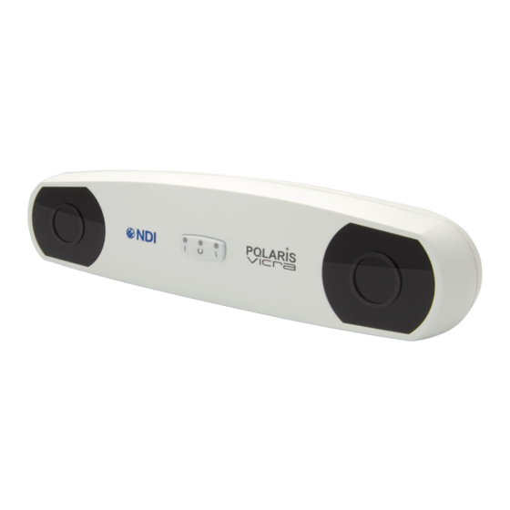
Polaris Vicra
Northern Digital Polaris Vicra Manuals
Manuals and User Guides for Northern Digital Polaris Vicra. We have
1
Northern Digital Polaris Vicra manual available for free PDF download: User Manual
Northern Digital Polaris Vicra User Manual (102 pages)
Brand:
Northern Digital
| Category:
Medical Equipment
| Size: 1 MB
Table of Contents
Table of Contents
5
Read Me First
13
Warnings
13
Cautions
14
Disclaimers
15
Contact Information
16
Updates
16
About this Guide
17
Organization of Content
17
Polaris Vicra System Overview
18
Introduction
18
Figure 1-1 Polaris Vicra Measurement Volume
18
Position Sensor
19
Figure 1-2 Polaris Vicra System Setup
19
Figure 1-3 Position Sensor - Front View
20
Figure 1-4 Position Sensor - Rear View
21
Figure 1-5 Position Sensor - Serial Number Label
21
Host USB Converter
23
Power Adapter
24
Cables
24
Figure 1-6 Host USB Converter
24
Figure 1-7 Host USB Converter Serial Number Label
24
Polaris Vicra Tools
25
Figure 1-8 Sample Passive Tool
25
Polaris Vicra System Software
26
Component Parts List
26
Table 1-1 Component Parts List
26
Setting up the Polaris Vicra System
27
Unpacking the Polaris Vicra System
27
Polaris Vicra System Operating Environment
27
Mounting the Position Sensor
30
Figure 2-1 Position Sensor Mounting Details
30
Mounting the Host USB Converter
31
Connecting the Hardware
31
Figure 2-2 Host USB Converter Mounting Details
31
Installing the Software
32
Figure 2-3 Connecting Cables to the Host USB Converter
32
Installing the USB Drivers (Windows)
33
Linux Support
34
Keyed Features
36
How the Polaris Vicra System Works
37
Introduction
37
Information Returned by the Polaris Vicra System
37
Global Coordinate System and Measurement Volume
38
Figure 3-1 Position Sensor Global Coordinate System
38
Figure 3-2 Characterized Measurement Volume
39
Marker Detection and Tool Tracking
40
Figure 3-3 Determining a Marker Position
41
Polaris Vicra System Tools
42
Tool Definition File
43
Tool Tracking Parameters
43
Figure 3-4 Marker with Marker Normal
44
Figure 3-5 Maximum Marker Angle
44
Figure 3-6 Flowchart of Tool Tracking Parameters Use
46
Tool Tip Offset
47
Reference Tool
48
Figure 3-7 Sample Calibrator
48
Stray Marker Reporting
49
Phantom Markers
50
Passive Sphere Markers
50
Figure 3-8 Phantom Markers
50
Active Markers
51
Filter Spectral Response
51
Data Transmission Rate
52
Serial Port Emulation
52
Figure 3-9 Filter Spectral Response
52
Using the Polaris Vicra System
53
Getting Started: Tracking Tools
53
Information and Error Flags
54
Figure 4-1 Tool Tracking Window
54
Figure 4-2 Partially out of Volume Flag
55
Figure 4-3 Markers Information Pane - Missing Marker
55
Figure 4-4 Transformation Pane - too few Markers
55
Setting a Tool as Reference
56
Figure 4-5 Markers Information Pane - Exceeded Max Marker Angle
56
Figure 4-6 Selecting a Reference Tool
56
Determining the Tool Tip Offset
57
Figure 4-7 Selecting a Tool to Pivot
58
Figure 4-8 Pivoting Technique
59
Figure 4-9 Pivot Result Dialog
59
Error Flags and Codes
60
Missing and Disabled Transformations
60
Tracking Errors and Flags
61
Polaris Vicra System Leds and Audio Codes
63
Maintenance
64
Position Sensor
64
Cables and Connectors
65
Figure 6-1 How to Avoid Stressed Cables
65
Setting the Infrared Light Sensitivity
66
IR Light Sensitivity Levels
66
Changing the Sensitivity Level
67
Figure 7-1 Infrared Light Sensitivity Levels
67
Calibration and Firmware
69
Checking the Calibration of the Polaris Vicra System
69
Updating the Firmware
70
Approvals
71
Optical Radiation Safety
71
Table 9-1 Electrical Safety
71
Table 9-2 Electromagnetic Compatibility
71
Classifications
72
Table 10-1 Classifications
72
Technical Specifications
73
Position Sensor
73
Table 11-1 Position Sensor - Technical Specifications
73
Table 11-2 Position Sensor - Operating Environmental Conditions
73
Host USB Converter
74
Table 11-3 Position Sensor - Transportation and Storage Environmental Conditions
74
Table 11-4 Host USB Converter - Technical Specifications
74
Table 11-5 Host USB Converter - Operating Environmental Conditions
74
Table 11-6 Host USB Converter - Transportation and Storage Environmental Conditions
74
Power Adapter
75
Table 11-7 Power Adapter - Technical Specifications
75
Table 11-8 Power Adapter - Operating Environmental Conditions
75
Table 11-9 Power Adapter - Transportation and Storage Environmental Conditions
75
Electromagnetic Compatibility
76
Electrostatic Discharge
76
Cables and Accessories
76
Table 12-1 Cables and Accessories that Maintain Compliance
76
Guidance and Manufacturer's Declaration - Electromagnetic Emissions
77
Guidance and Manufacturer's Declaration - Electromagnetic Immunity
77
Table 12-2 Manufacturer's Declaration for Electromagnetic Emissions
77
Table 12-3 Electromagnetic Immunity
77
Table 12-4 Electromagnetic Immunity - Not Life Supporting
79
Recommended Separation Distances
80
RF Emissions
80
Table 12-5 Recommended Separation Distances
80
Troubleshooting
82
Introduction
82
System Indications
82
Table 13-1 System Visual and Audio Indications
82
NDI Toolbox Error Messages
84
Figure 13-1 Host USB Converter - Error LED Fault Chart
84
Table 13-2 NDI Toolbox Error Messages
85
Common Problems
86
Return Procedure and Warranty
89
Return Procedure
89
Warranty
89
Abbreviations and Acronyms
91
Equipment Symbols
92
Glossary
93
Declaration of Conformity
96
Figure 18-1 EC Declaration of Conformity
96
Appendix A Polaris Vicra Calibration Performance and Methodology
97
Polaris Vicra Performance
97
Calibration Method
97
Advertisement
Advertisement
Related Products
Northern Digital Passive Polaris Vega
Northern Digital Categories
Medical Equipment
Laboratory Equipment
More Northern Digital Manuals
Login
Sign In
OR
Sign in with Facebook
Sign in with Google
Upload manual
Upload from disk
Upload from URL