Sign In
Upload
Manuals
Brands
Motorola Manuals
Network Hardware
PTP 400 Series
Motorola PTP 400 Series Manuals
Manuals and User Guides for Motorola PTP 400 Series. We have
2
Motorola PTP 400 Series manuals available for free PDF download: User Manual
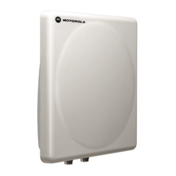
Motorola PTP 400 Series User Manual (208 pages)
Point-to-Point Wireless Bridges
Brand:
Motorola
| Category:
Network Hardware
| Size: 2.98 MB
Table of Contents
Table of Contents
9
Table 1 - Font Types
19
Table 2 - Admonition Types
20
Getting Additional Help
21
Sending Feedback
21
1 About this User Guide
19
Interpreting Typeface and Other Conventions
19
2 Avoiding Hazards
22
Preventing Overexposure to RF Energy
22
Calculations for Separation Distances and Power Compliance Margins
22
Calculated Distances and Power Compliance Margins
23
Table 3 - Power Compliance Margins
23
3 Getting Started
24
For Your Safety
24
Welcome
25
About this Guide
25
Who Should Use this Guide
25
Contact Information
26
Repair and Service
26
Table 4 - Contact Information
26
Product Description
27
Figure 1 - Typical PTP 400 Series Bridge Deployment
27
The Outdoor Unit (ODU)
29
Figure 2 - PTP 400 Series Bridge Outdoor Unit (ODU)
29
The PIDU Plus - PTP 400 Series
30
Figure 3 - Power Indoor Unit (PIDU Plus) - PTP 400 Series
30
Figure 4 - PTP 400 Series Bridge Recovery Switch Location
30
Table 5 - Reset Actions
31
Redundancy and Alternate Powering Configurations
32
External DC Supply Only
32
Figure 5 - PTP 400 Series Bridge PIDU Plus Power Input
32
Figure 6 - External DC Supply Only
32
External DC Supply and AC Supply
33
External DC Supply and Redundant AC Supply
33
Figure 7 - External DC Supply and AC Supply
33
Figure 8 - External DC Supply and Redundant AC Supply
33
Remote Leds and Recovery Switch
34
Cables and Connectors
34
Figure 9 - Remote LED and Recovery Switch Wiring
34
Surge Arrestor
35
Mounting Brackets
35
Configuration and Management
36
Warranty
36
4 Product Architecture
37
Figure 10 - PTP 400 Series Bridge Layer Diagram
38
5 General Considerations
39
Spectrum Planning
39
Table 6 - PTP 400 Series Bridge Frequency Variants
39
Region Codes
40
Table 7 - PTP 400 Series Bridge Region Code Definitions
40
Operational Restrictions
41
Radar Avoidance
41
RTTT Avoidance and Other Channel Use Restrictions
42
Ghz Specific Frequency Planning Considerations
42
Raster Considerations
42
Fixed Frequency Operation
42
Figure 11 - 5.8 Ghz UK RTTT Channel Avoidance
42
Figure 12 - 4.9 Ghz Spectrum Settings
42
Transmit Power Reduction at the Band Edges
43
Ghz Specific Frequency Planning Considerations
43
Raster Considerations
43
Fixed Frequency Operation
43
Figure 13 - 5.4 Ghz Available Spectrum Settings
43
Ghz Specific Frequency Planning Considerations
44
Raster Considerations
44
Fixed Frequency Operation
44
Transmit Power Reduction at the Band Edges
44
Figure 14 - 5.8 Ghz Available Spectrum Settings
44
Distance
45
Networking Information
45
Lightning Protection
45
Figure 15 - 5.8 Ghz Band Edge TX Power Reduction (Region Code 1 Only)
45
Electrical Requirements
46
6 Site Planning
47
Site Selection Criteria
47
ODU Site Selection
47
PTP 400 Series Bridge PIDU Plus Site Selection
47
Path Loss Considerations
48
Aggregate Ethernet Throughput Rate Versus Maximum Link Loss
48
Equation 1 - Path Loss
48
Table 8 - 5.4 and 5.8 Ghz Variants - Aggregate Ethernet Throughput Rates
49
Table 9 - 4.9 Ghz Variant - Aggregate Ethernet Throughput Rates
50
7 Installation
51
Preparation
51
Installation Procedure
51
Tools Required
51
Installation Support
52
Legal Disclaimer
52
Mounting the Odus
52
Figure 16 - Mounting to Pole Diameters 25Mm (1") to 50Mm (2")
53
Figure 17 - Integral Safety Loop
53
Connecting up
54
Preparing the Cable - RJ45 Connections
54
Figure 18 - Completed ODU Connector
55
Figure 19 - RJ45 Pin Connection
55
Making the Connection at the ODU
56
Figure 20 - Connections at the ODU
56
Routing the Cable
57
Fitting a Surge Arrestor
57
Figure 21 - Disconnecting the ODU
57
Grounding the Installation
58
Making the ODU Connection at the PTP 400 Series Bridge PIDU Plus
58
Making the Network Connection at the PIDU Plus - PTP 400 Series
59
Figure 22 - Making the Network Connection at the PTP 400 Series Bridge PIDU Plus
59
Mounting the PTP 400 Series Bridge PIDU Plus
60
Figure 23 - PTP 400 Series Bridge PIDU Plus Drip Loop Configuration
61
Powering up
62
Aligning the PTP 400 Series Odus
63
Table 10 - Audio Indications from the ODU
63
8 Web
66
Figure 24 - Menu Navigation Bar
66
Home Page - PTP 400 Series Bridge
67
Figure 25 - PTP 400 Series Bridge Home Page
67
Home Page Alarm Display
68
Figure 26 - Alarm Warning Triangle
68
System Status Page
70
Figure 27 - Status Page
70
Equation 2 - Link Loss
74
System Administration
76
Figure 28 - System Administration Login Page
76
System Configuration Page
77
Figure 29 - Configuration Page
77
Figure 30 - Configuration Reboot Page
79
LAN Configuration Page
80
Figure 31 - LAN Configuration Page
80
Figure 32 - VLAN Warning Window
81
Figure 33 - Additional VLAN Options
82
Save and Restore Menu
84
Figure 34 - Save and Restore Configuration Page
84
Figure 35 - Save Configuration File Screen
85
Figure 36 - Example Configuration File
86
Figure 37 - Restore Configuration File Pop up Screen
87
Figure 38 - Reset Configuration and Reboot Confirmation Pop-Up
88
Statistics Page
89
Figure 39 - System Statistics
89
Detailed Counters Page
92
Figure 40 - Detailed Counters
92
Install Wizard
95
Table 11 - PTP 400 Series Bridge Factory Configuration Values
95
Manually Configuring the Wireless Units
96
Internet Protocol Configuration
96
Figure 41 - Installation Wizard Internet Protocol Configuration
96
Figure 42 - VLAN Warning
97
Figure 43 - Additional VLAN Management Options
98
Wireless Configuration
99
Figure 44 - Installation Wizard Wireless Configuration
99
Figure 45 - Fixed Frequency Operation
102
Confirm Configuration
104
Figure 46 - Installation Wizard Confirm Configuration
104
Figure 47 - Installation Wizard Confirm Configuration - Fixed Frequency
105
Figure 48 - Installation Wizard Confirm Configuration - Connectorized
106
Disarm
107
Figure 49 - Disarm Installation
107
Figure 50 - Optional Post Disarm Configuration 2
108
Graphical Install
109
Figure 51 - Installation Screen
109
Software Upgrade
110
Figure 52 - Software Upgrade - Step 1
111
Figure 53 - Software Upgrade Image Check
112
Figure 54 - Overall Progress Tracker
112
Figure 55 - Software Upgrade Complete
113
Spectrum Management
114
Wireless Channels
114
Spectrum Management Measurements
114
Measurement Analysis
114
The Spectrum Management Master / Slave Relationship
116
Figure 56 - Spectrum Management - Master
117
Spectrum Management Configuration
118
Figure 57 - Spectrum Management - Slave
118
Barring Channels
119
Local and Peer Channel Spectrum Graphics
120
Figure 58 - Sample Spectrum Management Graphic
120
Table 12 - Spectrum Management (Non UK) Change State Key
120
Active Channel History
121
Figure 59 - Active Channel History Screen
121
Viewing Historic Spectrum Management Metrics
122
Spectrum Management Online Help
122
Figure 60 - Spectrum Management Time Series Plot
122
Table 13 - Spectrum Management Time Series Key
122
Figure 61 - Spectrum Management Help Page
123
Spectrum Management - Fixed Frequency
124
Figure 62 - Spectrum Management Fixed Frequency Screen- Master
124
Spectrum Management Control - with Operational Restrictions
125
Figure 63 - Spectrum Management Fixed Frequency Screen- Slave
125
Figure 64 - Spectrum Management Master Screen with Operational Restrictions
126
Figure 65 - Spectrum Management Slave Screen with Operational Restrictions
127
Table 14 - Spectrum Management Change State Key with Operational Restrictions
127
Remote Management Page
128
Figure 66 - Remote Management
128
SNMP (Simple Network Management Protocol)
129
Supported Management Information Bases (MIBS)
129
SNMP Configuration
129
SMTP (Simple Mail Transport Protocol)
130
SNTP (Simple Network Time Protocol)
131
Diagnostics
132
Diagnostics Plotter
133
Figure 67 - Diagnostic Plotter
133
Diagnostic Download
134
Figure 68 - CSV Download
134
Change System Administration Password
135
Figure 69 - Password Change
135
License Key
136
Figure 70 - Software License Key Data Entry
136
Properties
137
Figure 71 - License Key Reboot Screen
137
Figure 72 - Webpage Properties
137
Reboot
138
Figure 73 - System Reboot
138
9 Fault Finding
139
Hardware
139
Power
139
Figure 74 - Main System Connections
139
Ethernet
140
Radio
142
No Activity
142
Some Activity
142
10 System Connections
143
ODU to PIDU Plus Connection
143
Figure 75 - ODU to PIDU Plus Connection Diagram
143
11 Lightning Protection
144
Overview
144
Lightning Protection Zones
144
Detailed Installation
145
Figure 76 - ODU Mounted in Zones a & B
146
Figure 77 - Showing How the Use of a Finial Enables the ODU to be Mounted Inside Zone B
146
Figure 78 - Diagrammatically Showing Typical Wall and Mast Installations
147
Table 15 - Protection Requirements
147
Figure 79 - Upper Grounding Configuration
148
Figure 80 - Lower Grounding Configuration
149
Table 16 - Surge Arrestor ALPU-ORT Cable 1 Termination
150
Table 17 - Surge Arrestor ALPU-ORT Cable 2 Termination
151
Figure 81 - Surge Arrestor ALPU-ORT Connection Illustration
152
Testing Your Installation
153
Pre-Power Testing
153
Figure 82 - Simplified Circuit Diagram (Only One Transtector Shown for Clarity)
153
Post-Power Testing
154
Table 18 - Resistance Table Referenced to the RJ45 at the PIDU Plus
154
12 Wind Loading
155
General
155
Calculation of Lateral Force
155
Capabilities of the PTP 400 Series Bridges
156
Wind Speed Statistics
156
13 PTP 400 Series Bridge - Connectorized Version of the PTP 400 Series Bridge
157
Scope
157
Product Description
157
Hardware
157
Figure 83 - Connectorized Version of the PTP 400 Series Bridge Outdoor Unit
157
Antenna Choices - 4.9 Ghz
158
Antenna Choices - 5.8 Ghz
158
Software/Features
158
Status Page
159
Figure 84 - Connectorized Version of the PTP 400 Series Bridge Status Page
159
Configuration
160
Figure 85 - Connectorized Version of the PTP 400 Series Bridge 'System Configuration' Page
160
Installation
161
Figure 86 - Connectorized Version of the PTP 400 Series Bridge 'Installation Wizard' Page
161
Figure 87 - Connectorized Version of the PTP 400 Series Bridge 'Confirm Installation' Page
162
Figure 88 - Connectorized Version of the PTP 400 Series Bridge 'Disarm Installation' Page
163
Deployment Considerations
164
Link Budget
164
Regulatory Issues
164
Antenna Choice (5.8Ghz FCC Regions Only)
164
Cable Losses (5.8 Ghz FCC Regions Only)
165
Antennas for 5.8Ghz FCC Regions
165
Table 19 - Cable Losses Per Length
165
Installation
167
Antenna Choice
167
Table 20 - Allowed Antennas for Deployment in Usa/Canada
167
Cables and Connectors
168
Tools
168
Miscellaneous Supplies
168
Mounting
168
Connectorized Version of the PTP 400 Series Bridge
168
Antennas
169
Alignment Process
169
Dual Polar Antennas
169
Separate Antennas
169
Completing the Installation
170
Antenna Cable Fixing
170
Antenna Connection Weatherproofing
171
Figure 89 - Forming a Drip Loop
171
Figure 90 - Weatherproofing the Antenna Connections
171
Additional Lightning Protection
172
ODU Mounted Outdoors
172
Figure 91 - Additional Grounding When Using Connectorized Units
172
ODU Mounted Indoors
173
Figure 92 - Lightning Arrestor Mounting
173
Figure 93 - Polyphaser Assembly
174
14 Wireless Link Encryption
175
Configuring Link Encryption
175
License Keys
175
Figure 94 - Software License Key Data Entry
176
Encryption Mode and Key
177
Figure 95 - Configuration Data Entry Page
177
Wireless Link Encryption FAQ
178
Encryption Data Entry Fields Are Not Available
178
Link Fails to Bridge Packets after Enabling Link Encryption
178
Figure 96 - Configuration Reboot Screen
178
15 Legal and Regulatory Notices
179
Important Note on Modifications
179
National and Regional Regulatory Notices - 4.9 Ghz Variant
179
National and Regional Regulatory Notices - 5.8 Ghz Variant
179
Federal Communication Commission (FCC) and Industry Canada (IC) Notification
179
Table 21 - US FCC Ids and Industry Canada Certification Numbers
179
Table 22 - US FCC Ids and Industry Canada Certification Numbers
180
European Union Notification
181
UK Notification
182
Exposure
182
Legal Notices
182
Software License Terms and Conditions
182
Hardware Warranty in U.S
186
Limit of Liability
186
16 Glossary
187
17 Faqs
188
18 Specifications
192
System Specifications
192
Wireless 4.9Ghz Variant
192
Wireless 5.4Ghz Variant
195
Wireless 5.8Ghz Variant
198
Management
201
Ethernet
202
Physical
203
Powering
203
Safety Compliance
204
EMC Emissions Compliance
204
Ghz Variant
204
EMC Immunity Compliance - Europe Only
205
Radio Certifications
206
Ghz Variant
206
Environmental Specifications
207
Advertisement
Motorola PTP 400 Series User Manual (61 pages)
PTP Solutions Guide Motorola Fixed Point-to-Point Wireless Bridges
Brand:
Motorola
| Category:
Network Hardware
| Size: 1.87 MB
Table of Contents
Table of Contents
2
Introduction
3
Solutions Overview
4
Motorola PTP 100 and 200 Warranties
10
Motorola PTP 300, 400, 500 and 600 Warranties
11
PTP Portfolio Summary
12
Key PTP 100 and 200 Selling Points
13
Key PTP 300, 400, 500 and 600 Selling Points
14
PTP 300, 400, 500 and 600 Value Proposition
17
PTP 100 Products
19
PTP 200 Product Descriptions
19
PTP 300, 400, 500 and 600 Product Descriptions
21
Key PTP 300, 400, 500 and 600 Technical Features
22
PTP 400 Series Bridges - Aggregate Ethernet Throughput Rates
26
PTP 600 Series Bridges - Aggregate Ethernet Throughput Rates
27
PTP Lightning Protection Unit (PTP-LPU) Product Description
28
Memorylink Ultrasync™ GPS-100M Synchronization Unit
31
Frequently Asked Questions
35
Motorola PTP 100 Series Products and Part Numbers
40
Motorola PTP 200 Series Products and Part Numbers
41
Motorola PTP 300 Series Products and Part Numbers
42
Motorola PTP 400 Series Products and Part Numbers
43
Motorola PTP 500 Series Products and Part Numbers
45
Motorola PTP 600 Series Products and Part Numbers
46
Motorola PTP 300, PTP 500 and PTP 600 Series Accessories
48
Motorola PTP-LPU Kits and Part Numbers
49
51 Appendix A: Specifications for 5.4 and 5.8 Ghz PTP 300 Series Solutions
52
50 Appendix A: Specifications for 5.4 Ghz PTP 200 Series Solutions
52
Appendix A: Specifications for 5.4 Ghz PTP 400 Series Solutions
52
Appendix A: Specifications for 4.9 Ghz PTP 400 Series Solutions
53
54 Appendix A: Specifications for 5.4 and 5.8 Ghz PTP 500 Series Solutions
55
Appendix A: Specifications for 5.4 and 5.8 Ghz PTP 600 Series Solutions
55
Appendix A: Specifications for 2.5 Ghz PTP 600 Series Solutions
56
Appendix A: Specifications for 4.5 Ghz PTP 600 Series Solutions
57
Appendix A: Specifications for the PTP-LPU
58
Appendix B: External Antennas
59
Advertisement
Related Products
Motorola PTP 49200
Motorola PTP 49400
Motorola PTP 49400 Lite
Motorola PTP 45600
Motorola PTP 54230
Motorola PTP 24100 Lite
Motorola PTP 52100 Lite
Motorola PTP 58100
Motorola PTP 58100 Lite
Motorola PTP 54200
Motorola Categories
Cell Phone
Two-Way Radio
Baby Monitor
Cordless Telephone
Radio
More Motorola Manuals
Login
Sign In
OR
Sign in with Facebook
Sign in with Google
Upload manual
Upload from disk
Upload from URL