Sign In
Upload
Manuals
Brands
Mitsubishi Electric Manuals
Air Conditioner
PUHY-P200
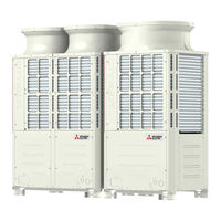
Mitsubishi Electric PUHY-P200 Manuals
Manuals and User Guides for Mitsubishi Electric PUHY-P200. We have
3
Mitsubishi Electric PUHY-P200 manuals available for free PDF download: Service Handbook
Mitsubishi Electric PUHY-P200 Service Handbook (334 pages)
Brand:
Mitsubishi Electric
| Category:
Air Conditioner
| Size: 14.06 MB
Table of Contents
8
Chapter 1 Check before Servicing
2
Safety Precautions
8
Table of Contents
12
Preparation for Piping Work
12
Read before Servicing
13
Tool Preparation
14
Handling and Characteristics of Piping Materials, Refrigerant, and Refrigerant Oil
14
Piping Materials
16
Pipe Processing
16
Storage of Piping Materials
17
Characteristics of the New and Conventional Refrigerants
18
Refrigerant Oil
19
Working with Refrigerant Piping
19
Pipe Brazing
20
Air Tightness Test
21
Vacuum Drying
22
Refrigerant Charging
23
Precautions for Wiring
25
Cautionary Notes On Installation Environment and Maintenance
26
Chapter 2 Restrictions
28
System Configurations
29
Types and Maximum Allowable Length of Cables
30
Switch Settings
31
Address Settings List
31
M-NET Address Settings
32
Outdoor Unit Centralized Controller Switch Setting
32
Outdoor Unit Power Jumper Connector Connection
32
Room Temperature Detection Position Selection
33
Miscellaneous Settings
33
Start/Stop Control of Indoor Units
34
Various Control Methods Using the Signal Input/Output Connector On Outdoor Unit
37
Demand Control Overview
39
System Connection Example
41
Example System with an MA Remote Controller
41
Single Refrigerant System (Automatic Indoor/Outdoor Address Startup)
43
Single Refrigerant System with Two or More LOSSNAY Units
45
Grouped Operation of Units in Separate Refrigerant Circuits
47
System with a Connection of System Controller to Centralized Control Transmission Line
49
System with a Connection of System Controller to Indoor-Outdoor Transmission Line
51
Example System with an ME Remote Controller
51
System with a Connection of System Controller to Centralized Control Transmission Line
53
Example System with an MA and an ME Remote Controller
53
System with a Connection of System Controller to Centralized Control Transmission Line
55
2-10 Restrictions On Refrigerant Pipes
55
Restrictions On Refrigerant Pipe Length
58
Restrictions On Refrigerant Pipe Size
60
Chapter 3 Major Components, Their Functions and Refrigerant Circuits
62
External Appearance and Refrigerant Circuit Components of Outdoor Unit
62
External Appearance of Outdoor Unit
65
Outdoor Unit Refrigerant Circuits
68
Outdoor Unit Refrigerant Circuit Diagrams
70
Functions of the Major Components of Outdoor Unit
73
Functions of the Major Components of Indoor Unit
74
Chapter 4 Electrical Components and Wiring Diagrams
76
Outdoor Unit Circuit Board Arrangement
76
Outdoor Unit Control Box
79
Fan Box
80
Control Board
80
Outdoor Unit Circuit Board Components
81
M-NET Board (Transmission Power Supply Board)
82
INV Board
84
Fan Board
85
Noise Filter
87
Capacitor Board
88
Connect Board
89
Outdoor Unit Electrical Wiring Diagrams
91
Transmission Booster Electrical Wiring Diagrams
92
Chapter 5 Control
94
Dipswitch Functions and Factory Settings
94
Outdoor Unit Switch Functions and Factory Settings
98
Indoor Unit Switch Functions and Factory Settings
100
Remote Controller Switch Functions and Factory Settings
102
Initial Control
102
Outdoor Unit Control
102
Overview
102
Rotation Control
102
Startup Control
103
Refrigerant Bypass Control
104
Frequency Control
105
Defrost Operation Control
106
Continuous Heating Mode Control
107
Refrigerant Recovery Control
108
Control at Initial Startup
108
Outdoor Unit Fan Control
108
Refrigerant Flow Control (Linear Expansion Valves 2A and 2B)
108
Subcool Coil Control (Linear Expansion Valve 1)
111
Emergency Operation Mode
114
Compressor Heater Control (P450 and P500 Models)
114
Control of IH Energization Without the Compressor in Operation (Not Applicable to the P450 and P500 Models)
114
Demand Control
114
Operation Mode
115
Operation Flowcharts
115
Operation Sequence Flowchart
117
Actions Performed in Different Modes
120
Chapter 6 Test Run
122
Read before Test Run
123
Function/Specification Comparison
123
Local Remote Controller Selection Tips
123
MA and ME Remote Controller Functions and Specifications
124
Address Registration
124
Making the Group and Interlock Settings From an ME Remote Controller
124
Overview
126
Address Search
127
Address Deletion
127
Making Group and Interlock Settings From Another Remote Controller
128
Selecting Remote Controller Functions From an ME Remote Controller
130
MA Remote Controller (PAR-31MAA)
130
Making Interlock Settings From an MA Remote Controller
131
MA Remote Controller (PAR-21MAA)
133
MA Simple Remote Controller
136
Changing the Room Temperature Detection Position
137
MA Remote Controller (PAR-31MAA)
137
Test Run Method
139
MA Remote Controller (PAR-21MAA)
140
Checking the Refrigerant Charge During Operation
140
Evaluating and Adjusting Refrigerant Charge
140
Operation Characteristics and Refrigerant Charge
140
Refrigerant Overcharge and Undercharge
141
The Amount of Refrigerant to Be Added
144
Refrigerant Charge Adjustment Mode
146
6-10 the Following Symptoms Are Normal
147
Single Unit (Standard)
147
Standard Operation Data (Reference Data)
148
Cooling Operation
148
Heating Operation
151
Dual Unit Combination (Standard)
162
Triple Unit Combination (Standard)
172
Chapter 7 Troubleshooting Using Error Codes
174
Error Code and Preliminary Error Code Lists
178
Error Code Definitions and Solutions: Codes [0 - 999]
178
Error Code [0403]
179
Error Code [0404]
180
Error Code Definitions and Solutions: Codes [1000 - 1999]
180
Error Code [1102]
181
Error Code [1301]
182
Error Code [1302] (During Operation)
183
Error Code [1302] (At Startup)
183
Error Code [1500]
184
Error Code Definitions and Solutions: Codes [2000 - 2999]
184
Error Code [2500] (Models with a Drain Sensor)
185
Error Code [2500] (Models with a Float Switch)
186
Error Code [2502] (Models with a Drain Sensor)
187
Error Code [2502] (Models with a Float Switch)
188
Error Code [2503]
189
Error Code [2600]
189
Error Code [2601]
190
Error Code Definitions and Solutions: Codes [3000 - 3999]
190
Error Code [3121]
191
Error Code Definitions and Solutions: Codes [4000 - 4999]
191
Error Code [4102]
192
Error Code [4106]
192
Error Code [4109]
193
Error Code [4115]
193
Error Code [4116]
194
Error Code [4121]
195
Error Code [4124]
196
Error Codes [4220, 4225, 4226] Detail Code 108
197
Error Codes [4220, 4225, 4226] Detail Code 109
198
Error Code [4220] Detail Code 110
198
Error Codes [4220, 4225, 4226] Detail Code 111, 112
199
Error Code [4220] Detail Code 123
199
Error Code [4220] Detail Code 124
200
Error Code [4230] Detail Code 125
200
Error Codes [4220, 4225, 4226] Detail Code 131
201
Error Code [4230] Detail Code 126
202
Error Code [4240]
203
Error Codes [4250, 4255, 4256] Detail Code 101
204
Error Codes [4250, 4255, 4256] Detail Code 104
205
Error Code [4250] Detail Codes 106 and 107
205
Error Codes [4250, 4255, 4256] Detail Code 105
206
Error Code [4250] Detail Codes 121, 128, and 122
206
Error Code [4260]
207
Error Code Definitions and Solutions: Codes [5000 - 5999]
207
Error Codes [5101, 5102, 5103, 5104]
208
Error Codes [5102,5103,5104,5105,5106,5107,5109,5111]
209
Error Code [5110]
210
Error Code [5120]
210
Error Code [5201]
211
Error Code [5301] Detail Code 115
211
Error Code [5301] Detail Code 117
212
Error Code [5301] Detail Code 119
212
Error Code [5301] Detail Code 120
213
Error Code [5301] Detail Code 127
213
Error Codes [5305, 5306] Detail Code 132
214
Error Code [5701]
214
Error Codes [5305, 5306] Detail Code 133
214
Error Codes [5305, 5306] Detail Code 134
215
Error Code Definitions and Solutions: Codes [6000 - 6999]
215
Error Code [6201]
215
Error Code [6202]
216
Error Code [6600]
216
Error Code [6601]
217
Error Code [6602]
218
Error Code [6603]
218
Error Code [6606]
219
Error Code [6607] Error Source Address = Outdoor Unit (OC)
220
Error Code [6607] Error Source Address = Indoor Unit (IC)
221
Error Code [6607] Error Source Address = LOSSNAY (LC)
222
Error Code [6607] Error Source Address = ME Remote Controller
223
Error Code [6607] Error Source Address = System Controller
224
Error Code [6607] All Error Source Addresses
225
Error Code [6607] No Error Source Address
226
Error Code [6608]
227
Error Code [6831]
228
Error Code [6832]
229
Error Code [6833]
230
Error Code [6834]
231
Error Code [6840]
231
Error Code [6841]
232
Error Code [6842]
233
Error Code [6843]
234
Error Code [6846]
235
Error Code Definitions and Solutions: Codes [7000 - 7999]
235
Error Code [7100]
236
Error Code [7101]
237
Error Code [7102]
238
Error Code [7105]
238
Error Code [7106]
239
Error Code [7110]
239
Error Code [7111]
240
Error Code [7113]
241
Error Code [7117]
242
Error Code [7130]
244
Chapter 8 Troubleshooting Based On Observed Symptoms
246
MA Remote Controller Problems
246
The LCD Does Not Light Up
247
The LCD Momentarily Lights Up and Then Goes Off
248
HO" and "PLEASE WAIT" Do Not Go Off the Screen
249
Air Conditioning Units Do Not Operate When the ON Button Is Pressed
250
ME Remote Controller Problems
250
The LCD Does Not Light Up
251
The LCD Momentarily Lights Up and Then Goes Off
252
HO" Does Not Go Off the Screen
253
88" Appears On the LCD
254
Refrigerant Control Problems
254
Units in the Cooling Mode Do Not Operate at Expected Capacity
256
Units in the Heating Mode Do Not Operate at Expected Capacity
258
Outdoor Units Stop at Irregular Times
259
Checking Transmission Waveform and for Electrical Noise Interference
259
M-Net
261
MA Remote Controller
262
Comparing the High-Pressure Sensor Measurement and Gauge Pressure
262
High-Pressure Sensor Configuration (63HS1)
262
Pressure Sensor Circuit Configuration and Troubleshooting Pressure Sensor Problems
263
Comparing the Low-Pressure Sensor Measurement and Gauge Pressure
263
Low-Pressure Sensor Configuration (63LS)
264
Troubleshooting Solenoid Valve Problems
266
Troubleshooting Outdoor Unit Fan Problems
267
General Overview On LEV Operation
267
Troubleshooting LEV Problems
270
Possible Problems and Solutions
271
Coil Removal Instructions
273
Inverter-Related Problems and Solutions
273
Troubleshooting Inverter Problems
275
Checking the Compressor for Ground Fault and Coil Resistance Problems
275
Checking the Inverter Board Error Detection Circuit
275
Checking the Inverter for Damage at No-Load
276
Checking the Inverter for Damage During Compressor Operation
278
Checking the Converter for Damage During Compressor Operation
278
Checking the Fan Board Error Detection Circuit at No Load
278
Checking the Fan Motor for Ground Fault and Coil Resistance Problems
279
Checking the Fan Inverter for Damage at No Load
280
Checking the Fan Inverter for Damage with Load
280
Checking the Installation Conditions
281
Solutions for the Main Earth Leakage Breaker Trip
281
Solutions for the Main No-Fuse Breaker Trip
282
Simple Check On Inverter Circuit Components
282
Troubleshooting Problems with IGBT Module
285
8-10 Control Circuit
285
Control Power Supply Function Block
286
Indoor Unit
287
Troubleshooting Problems with Outdoor Unit Transmission Power Supply Circuit
290
8-11 Measures for Refrigerant Leakage
292
8-12 Compressor Replacement Instructions
294
Troubleshooting Problems Using the LED Status Indicators On the Outdoor Unit
296
Chapter 9 Led Status Indicators On the Outdoor Unit Circuit Board
298
How to Read the LED
298
LED Status Indicators
299
Initial LED Display
300
Clock Memory Function
301
LED Status Indicators Table
Advertisement
Mitsubishi Electric PUHY-P200 Service Handbook (355 pages)
Brand:
Mitsubishi Electric
| Category:
Air Conditioner
| Size: 8 MB
Table of Contents
2
Safety Precautions
4
Precautions for Handling Units for Use with the Product
5
Before Installing the Unit
7
Before the Test Run
8
Table of Contents
10
Read before Servicing
12
1 I Read before Servicing
12
Read before Servicing
12
I Read before Servicing
13
Necessary Tools and Materials
14
Piping Materials
14
Copper Pipe Materials
14
Types of Copper Pipes
14
Radial Thickness
15
Flare Processing
15
Flare Nut
16
Storage of Piping
16
Pipe Processing
16
Sealing the Pipe Ends
17
Brazing
18
Air Tightness Test
19
Vacuum Drying (Evacuation)
19
Vacuum Pump with a Reverse-Flow Check Valve
19
Required Precision of Vacuum Gauge
19
Procedures for Stopping Vacuum Pump
20
Refrigerant Charging
20
Remedies to be Taken in Case of a Refrigerant Leak
21
Characteristics of the Conventional and the New Refrigerants
21
Refrigerant Composition
21
Pressure Characteristics
22
Notes on Refrigerating Machine Oil
22
Effects of Contaminants
24
2 Restrictions
26
System Configuration
26
Table of Compatible Indoor Units
27
High COP Combinations
28
Types and Maximum Allowable Length of Cables
28
Wiring Work
28
Control Wiring
28
M-NET Transmission Line
29
Switch Settings and Address Settings
29
Remote Controller Wiring
30
M-NET Address Settings
31
Power Supply Switch Connector Connection on the Outdoor Unit
31
Settings for the Centralized Control Switch for the Outdoor Unit
31
Selecting the Position of Temperature Detection for the Indoor Unit
31
Various Start-Stop Controls (Indoor Unit Settings)
32
Cooling-Only Setting for the Indoor Unit
32
Various Controls Using Input-Output Signal Connector on Outdoor Unit
33
Example of Wiring Connection
34
Demand Control
34
Contact Input and Control Content
35
8-Step Demand Control
35
12-Step Demand Control
36
Sample System Connection
37
An Example of a System to Which an MA Remote Controller Is Connected
38
Wiring Method
38
Indoor/Outdoor Transmission Line
38
MA Remote Controller Wiring
38
Address Setting Method
39
Sample Control Wiring
40
LOSSNAY Connection
41
Group Operation of Units in a System with Multiple Outdoor Units
47
An Example of a System to Which an ME Remote Controller Is Connected
49
An Example of a System to Which both MA Remote Controller and ME Remote Controller Are Connected
51
Restrictions on Pipe Length
53
Refrigerant Pipe Size
56
3 Outdoor Unit Components
58
Outdoor Unit Components and Refrigerant Circuit
58
Front View of an Outdoor Unit
60
Refrigerant Circuit Parts
62
Control Box of the Outdoor Unit Parts
63
Outdoor Unit Circuit Board
66
Fan Board
68
4 Remote Controller
70
Functions and Specifications of MA and ME Remote Controllers
70
Comparison of MA and ME Remote Controllers
70
Remote Controller Selection Criteria
71
Group Settings and Interlock Settings Via the ME Remote Controller
72
To Return to the Normal Display
73
Remote Controller Function Selection Via the ME Remote Controller
73
To Delete Group Settings
73
To Delete Interlock Settings
74
Skip-Auto-Mode Setting (Making Automatic Operation Mode Unselectable)
74
Operation Mode Display Selection Mode
74
Restricted Preset Temperature Range Mode
74
Temperature Range Setting for Heating/Automatic Mode
75
Interlock Settings Via the MA Remote Controller
76
Using the Built-In Temperature Sensor on the Remote Controller
76
Selecting the Position of Temperature Detection
78
5 Electrical Wiring Diagram
80
Electrical Wiring Diagram of the Outdoor Unit
82
Electrical Wiring Diagram of Transmission Booster
84
6 Refrigerant Circuit
86
Refrigerant Circuit Diagram
88
Principal Parts and Functions
92
7 Control
94
Functions and Factory Settings of the Dipswitches
94
Outdoor Unit Switches
98
Function of the Switch (Indoor Unit)
99
Function of the Switch - Remote Controller
101
Controlling the Outdoor Unit
101
Startup Sequence Rotation
101
Initial Control
101
Control at Start-Up
102
Bypass Control
103
Compressor Frequency Control
103
Pressure Limit
103
Discharge Temperature Limit
103
Periodic Frequency Control
104
Defrost Operation Control
104
Pipe Temperature
105
Stopping the Defrost Operation
105
Problems During Defrost Operation
105
Change in the Number of Operating Indoor Units During Defrosting
106
Refrigerant Recovery Control
106
Capacity Control of Outdoor Fan
107
Subcool Coil Control (Linear Expansion Valve LEV1)
107
Refrigerant Flow Control
107
Control at Initial Start-Up
110
Emergency Operation Mode
110
Starting the Emergency Operation
111
Ending the Emergency Operation
111
Communication Circuit Failure or When some of Outdoor Units Turned off
112
Operation Mode
114
Operation Flow Chart
114
Mode Determination Flowchart
116
Operations in each Mode
120
8 Test Run Mode
122
Items to be Checked before a Test Run
123
Test Run Method
124
Operating Characteristic and Refrigerant Amount
124
Adjusting the Refrigerant Amount
125
Amount of Refrigerant to be Added
127
Refrigerant Amount Adjust Mode
129
The Following Symptoms Are Normal
130
Standard Operation Data (Reference Data)
136
2-Unit Combination
162
3-Unit Combination
176
Single Unit (High-COP)
210
9 Troubleshooting
212
Error Code Lists
215
Responding to Error Display on the Remote Controller
267
Troubleshooting According to Remote Malfunction/External Input Error
275
Both for MA Remote Controller and ME Remote Controller
280
Investigation of Transmission Wave Shape/Noise
283
Troubleshooting Principal Parts
283
High-Pressure Sensor Troubleshooting
284
Low-Pressure Sensor Troubleshooting
285
Solenoid Valve Troubleshooting
286
Outdoor Unit Fan Troubleshooting
288
LEV Troubleshooting
294
Inverter Troubleshooting
296
Inverter Output Related Troubles
298
Trouble Treatment When the Main Power Breaker Is Tripped
298
Trouble Treatment When the Main Power Earth Leakage Breaker Is Tripped
299
Checking Procedure for Individual Components of Main Inverter Circuit
299
Troubleshooting for IGBT Module
301
Control Circuit Troubleshooting
301
Control Power Source Function Block
301
Indoor Unit
302
Troubleshooting Transmission Power Circuit of Outdoor Unit
303
Refrigerant Leak Troubleshooting
304
Leak Spot: in the Case of Extension Pipe for Indoor Unit
304
Leak Spot: in the Case of Outdoor Unit (Heating Season)
305
Compressor Replacement Instructions
307
Troubleshooting Using the Outdoor Unit LED Error Display
308
10 LED Monitor Display on the Outdoor Unit Board
310
How to Read the LED on the Service Monitor
310
LED Display at Initial Setting
311
Time Data Storage Function
312
LED Monitor Display - Current Data
322
LED Monitor Display - Data before Error
329
LED Monitor Display - Data on Indoor Unit System
336
LED Monitor Display - Setting Data
337
Data on Indoor Unit System
352
Other Types of Data
Mitsubishi Electric PUHY-P200 Service Handbook (182 pages)
city multi
Brand:
Mitsubishi Electric
| Category:
Air Conditioner
| Size: 4.68 MB
Table of Contents
2
Table of Contents
3
Safety Precautions
5
Before Installing the Unit
8
1 Read before Servicing
8
Items to Be Checked
9
Necessary Tools and Materials
10
Piping Materials
12
Storage of Piping Material
13
Piping Machining
14
Brazing
15
Airtightness Test
15
Vacuuming
16
Vacuum Drying
17
Changing Refrigerant
17
Remedies to Be Taken in Case of a Refrigerant Leak
18
Characteristics of the Conventional and the New Refrigerants
19
Notes On Refrigerating Machine Oil
20
2 Restrictions
20
Electrical Work & M-NET Control
21
Types of Switch Setting and Address Setting
23
Examples of System Connection
37
Restrictions On Refrigerant Piping Length
39
3 Components of the Outdoor Unit
39
Appearance of the Components and Refrigerant Circuit
45
Control Box
47
Circuit Board
51
4 Remote Controller
51
Functions and Specifications of MA and ME Remote Controllers
52
Group Setting and Interlocking Settings That Are Made On the ME Remote Controller
55
Interlocking Setting That Is Made On the MA Remote Controller
56
Switching to the Built-In Thermo On the Remote Controller
57
5 Electrical Wiring Diagram
57
Puhy-P200, P250, P300, P350, P400Ygm-A / Puy-P200, P250, P300, P350Ygm-A
58
Puhy-P450, P500, P550, P600, P650Ygm-A
59
Power Dispatching Extension Unit for the Transmission Lines
60
6 Refrigerant Circuit
60
Refrigerant Circuit Diagram
64
Functions of Principal Parts
66
7 Control
66
Dip Switch Functions and Their Factory Settings
71
Controlling the Outdoor Unit
78
Operation Flow Chart
83
8 Test Run
83
Check Items before Test Run
83
Test Run Method
84
Operating Characteristics and Refrigerant Amount
84
Adjustment and Judgment of Refrigerant Amount
86
Refrigerant Volume Adjustment Mode Operation
88
Symptoms That Do Not Signify Problems
89
Standard Operation Data (Reference Data)
97
9 Troubleshooting
97
Check Code List
100
Responding to Error Display On the Remote Controller
133
Investigation of Transmission Wave Shape/Noise
136
Troubleshooting of Principal Parts
153
Refrigerant Leak
155
Compressor Replacement Instructions (Only P450-P650 Types)
156
Collecting the Cooling Liquid From the Accumulator (Only P450-P650 Types)
157
LED Display
157
LED Monitor Display
Advertisement
Share and save
Advertisement
Related Products
Mitsubishi Electric PUHY-P200YMF-C
Mitsubishi Electric PUHY-P200YMF-B
Mitsubishi Electric CITY MULTI PUHY-P200YEM-A
Mitsubishi Electric City Multi PUHY-P200YNW-A
Mitsubishi Electric CITY MULTI PUHY-P204
Mitsubishi Electric PUHY-P216
Mitsubishi Electric City Multi PUHY-P240TSKMU-A
Mitsubishi Electric City Multi PUHY-P288TSKMU-A
Mitsubishi Electric CITY MULTI PUHY-P216TSJMU-A-BS
Mitsubishi Electric CITY MULTI PUHY-P240TSJMU-A-BS
Mitsubishi Electric Categories
Air Conditioner
Controller
Projector
Inverter
Monitor
More Mitsubishi Electric Manuals
Login
Sign In
OR
Sign in with Facebook
Sign in with Google
Upload manual
Upload from disk
Upload from URL