Sign In
Upload
Manuals
Brands
Mellanox Technologies Manuals
Switch
MSX6506-3R
Mellanox Technologies MSX6506-3R Manuals
Manuals and User Guides for Mellanox Technologies MSX6506-3R. We have
1
Mellanox Technologies MSX6506-3R manual available for free PDF download: Hardware Installation Manual
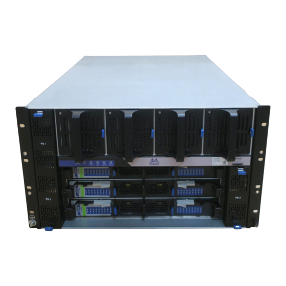
Mellanox Technologies MSX6506-3R Hardware Installation Manual (119 pages)
108-Port InfiniBand FDR SwitchX Switch Platform
Brand:
Mellanox Technologies
| Category:
Switch
| Size: 3 MB
Table of Contents
Table of Contents
3
List of Tables
5
List of Figures
6
About this Manual
8
Revision History
8
Table 1: Revision History of this Installation Guide
8
Table 2: Reference Documents and Websites
8
Chapter 1 Installation
11
Installation Safety Warnings
11
Environmental and Safety Recommendations
15
Chassis Package Contents
16
Leaf Package Contents
17
Spine Package Contents
17
Management Package Contents
17
Physical Installation
17
ESD Connection
18
Figure 1: Shelf Installation Kit Parts
19
Figure 2: Chassis Installation Parts
20
Figure 3: Shock and Tilt Stickers
21
Figure 4: Opening the Container
22
Figure 5: Placement of Chassis in Rack
23
Figure 6: Inserting the Caged Nuts for the Shelf
23
Figure 7: Connect Rail Slide to Rack Vertical Support
24
Figure 8: Inserting the Caged Nuts for the Faceplate
24
Figure 9: Chassis on Shelf with Filler Panel
25
Installing the Cable Holder
26
Figure 10: Cable Holders
26
Figure 11: Inserting the Caged Nuts for the Cable Holder
27
Figure 12: Cable Holder Placement
28
Installing the Chassis
29
Figure 13: Chassis Rails and Rail Slides
29
Figure 14: Installing the Handles
30
Figure 15: Screw the Handles Onto the Chassis
30
Figure 16: the Rails Are Already Connected Onto the Chassis
31
Figure 17: Raising the Chassis Using a Mechanical Lift
32
Figure 18: Put on the Rail Slide
32
Figure 19: SX6506 Chassis on the Shelf
33
Figure 20: Face Plate Mounting Bolt Locations
33
Ground Connections
34
Power Connections
34
Figure 21: Ground Connection
34
Powering up the Switch Platform
35
Figure 22: Do Not Use AC Power Socket #1 with N+N Psus
35
Figure 23: Multiple Power Inlets - Electric Caution Notification
35
Infiniband QSFP Cable Installation
36
Figure 24: Spine Module
36
Supported Approved Cables
37
Cable Power Classes
37
Hot Swap Insertion and Extraction
37
1.10.1 Power Supply Units
38
Figure 25: Power Cord Numbering
38
Figure 26: PSU Locations
39
1.10.2 Leaf Boards
40
Figure 27: Power Supply
40
Figure 28: Leaf Board Numbering
40
Figure 29: Ejector Handle
41
Figure 30: Leaf Release
41
Figure 31: Intact Vs Defected Signal Connectors
42
Figure 32: Intact Vs Defected Power Pin Holders
42
1.10.3 Spine Boards
43
Figure 33: Management Module Numbering
44
Figure 34: Spine Board Extraction
44
Figure 35: Intact Vs Defected Mechanics
46
Figure 36: Intact Vs Defected Side Signal Connectors
46
Figure 37: Intact Vs Defected Middle Signal Connectors
47
Figure 38: Intact Vs Defected Power Pin Holders
47
Figure 39: Spine Board Insertion Caution
47
1.10.4 Fan Modules
48
Figure 40: Leaf Fan Module Extraction
49
Figure 41: Spine Fan Module
49
1.10.5 Management Module
50
Figure 42: Fan Status LED on the Spine Module
50
Figure 43: Management Module
51
Figure 44: Intact Vs Defected Signal Connectors
51
Figure 45: Intact Vs Defected Power Pin Holders
52
1.10.6 Switch Shut-Down Procedures
53
Chapter 2 Interfaces
54
LED Status Indicators
54
Power Supply Unit Leds
54
Figure 46: Power Supply Unit Status Indications
54
Figure 47: PSU Cover on and off
55
Leaf Board LED Indicators
56
Table 3: Leaf Status LED
56
Table 4: Bad Port LED Configurations
56
Figure 48: Leaf Board Led Indicators
56
Spine Board LED Indicators
57
Table 5: Connector Physical and Logical Link Indications
57
Table 6: Spine Status LED
58
Table 7: Spine Fan Status LED
58
Figure 49: Spine Status Leds
58
Spine Side Panel Display LED Indicators
59
Table 8: Spine to Leaf IB Link Status
59
Table 9: Bad Port LED Configurations
59
Table 10: Leds Display for Normal Operation
60
Figure 50: Spine Side Panel Display Status Indications
60
Management Module LED Indicators
61
Table 11: Leds Display for Normal Operation
61
Figure 51: Management Module Status Indications
61
Figure 52: Management Module Leds
61
Port Connector Interfaces
62
Table 12: Management Module PSU LED Configurations
62
Table 13: Management Module S.fan LED Configurations
62
Table 14: Management Module L.fan LED Configurations
62
Table 15: Management Module MASTER LED Configurations
62
Air Flow
63
QSFP Cable Power Budget Classification
63
Management Module Interfaces
63
Figure 53: Port Numbering
63
Figure 54: Top and Bottom Ports
63
Figure 55: Management Module Interfaces
63
I2C
64
Console
64
MGT- Management
64
Usb
64
Reset - RST
64
Figure 56: Reset Button
65
Chapter 3 Chassis Power up
66
Figure 57: Do Not Use AC Power Socket #1 with N+N Psus
66
Power Supply and Spine Board Indicator Status at Power on
67
Figure 58: Spine Side Panel Display Status Indications
67
Figure 59: Management Module Status Indications for Normal Operation
67
Chapter 4 First-Time Configuration
68
Running the Wizard
68
Figure 60: Console Ports for Sx60Xx/Sx65Xx Managed Systems
68
Table 16: Serial Terminal Program Configuration
69
Table 17: Configuration Wizard Session - IP Configuration by DHCP
69
Table 18: Configuration Wizard Session - IP Zeroconf Configuration
71
Table 19: Configuration Wizard Session - Static IP Configuration
72
Re-Running the Wizard
73
Starting the Command Line (CLI)
73
Starting the Web User Interface
74
Figure 61: MLNX-OS Login Window
74
Figure 62: EULA Prompt
75
Figure 63: Display after Login
75
Chapter 5 Resetting the Switch - RST
76
Figure 64: Reset Button
76
Chapter 6 Troubleshooting
77
Power Supply Unit
77
Leaf Board
77
Management Module
78
Spine Board
79
MLNX-OS® Software
79
Chapter 7 Disassembly and Disposal
80
Disassembling the Chassis
80
Removing the Chassis
80
Removing the Bottom Shelf
80
Disposal
81
Appendix A Installation Safety Warnings
82
Installation Safety Warnings (English)
82
安裝安全性警告 (Chinese)
86
Avertissements de Sécurité Pour L'installation (French)
91
Installation Sicherheitshinweise(German)
96
Advertencias de Seguridad de Instalación (Spanish)
100
Предупреждения По Технике Безопасности При Установке (Russian)
104
Avertismente Privind Siguranţa la Instalare (Romanian)
108
Sigurnosna Upozorenja Za Instaliranje (Croatian)
113
Advertisement
Advertisement
Related Products
Mellanox Technologies MSX6512-NR
Mellanox Technologies MSX6512-4R
Mellanox Technologies MSX6536-NR
Mellanox Technologies MSX6536-10R
Mellanox Technologies MSX 6518-NR
Mellanox Technologies MSX6506-NR
Mellanox Technologies MSX6518-6R
Mellanox Technologies SwitchX MSX6018F-1BRS
Mellanox Technologies SwitchX-2 MSX6012T-1BRS
Mellanox Technologies SwitchX-2 MSX6005F-1BRS
Mellanox Technologies Categories
Switch
Computer Hardware
Adapter
Network Card
Network Router
More Mellanox Technologies Manuals
Login
Sign In
OR
Sign in with Facebook
Sign in with Google
Upload manual
Upload from disk
Upload from URL