Sign In
Upload
Manuals
Brands
Magtrol Manuals
Controller
DSP6000
Magtrol DSP6000 Manuals
Manuals and User Guides for Magtrol DSP6000. We have
1
Magtrol DSP6000 manual available for free PDF download: User Manual
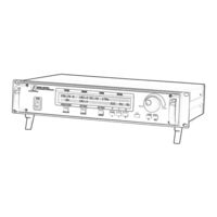
Magtrol DSP6000 User Manual (44 pages)
High Speed Programmable Dynamometer Controller
Brand:
Magtrol
| Category:
Controller
| Size: 4.99 MB
Table of Contents
Safety Notes
3
Table of Contents
5
Introduction
7
About this Manual
7
Shipping
7
Unpacking Your Dsp6000
7
About the Model DSP6000 Dynamometer Controller
7
Features
7
Specifications
8
Front Panel
9
Enabling Secondary Functions
9
Figure 1. Front Panel
9
Front Panel Controls and Buttons
10
Vacuum Fluorescent Display (VFD)
11
Status Display Messages
11
Displaying Desired Information
11
Rear Panel
12
Figure 2. Rear Panel
12
Figure 3. Brake Connector
12
Figure 4. Accessory Torque/Speed Output
12
Figure 5. Dynamometer Connector
12
Rear Panel Functions
13
About the Pid Loop
14
P (Proportional Gain)
14
I (Integral)
14
D (Derivative)
14
Figure 6. PID Loop
14
Setting the Correct PID'S for Your Motor
14
Installation
16
Setting Unit for Line Voltage
16
Figure 7. Cover for Voltage Selector, Fuses
16
Checking Your DSP6000
16
The Dsp6000 as a Stand-Alone Unit (Local Control)
18
Setting Desired Operating Parameters
18
Set Display to Desired Power Units (Watts or H P )
18
Set Display to Desired Torque Units
18
Set U P Display for Dynamometer
18
Set U P Communications with Pc
18
Set U P Auxiliary Input
18
Set Torque Control
18
Set Speed Control
19
Set Open Loop Control
19
Set U P I/O Parameters
19
Setting Dynamometer Load
20
Using Internal Memory
20
Storing Data Points
20
Recalling Data Points
20
Exiting the Memory Mode
20
Clearing the Memory
20
The Dsp6000 with a Pc (Remote Control)
21
About the GPIB Interface
21
Nstalling the Gpib (Ieee-488) Connector Able
21
Hanging the Gpib Primary
21
Ddress
21
Figure 8. GPIB (IEEE-488) Interface
21
Checking the DSP6000-To-PC Connection
22
Programming
22
Codes for Cr - Lf
22
DSP6000 Command Set
22
Command Set for Dsp6000
23
Acquiring Speed-Torque Data
26
Selecting the Baud Rate for the RS-232 Interface
26
Figure 9. Connector Pin-Out
26
Calibration
27
Closed-Box Calibration
27
Calibration Schedule
27
Basic Calibration Process
27
Initial Calibration Procedure
27
Torque Offset and Gain
27
Accessory Torque Offset and Gain
28
Auxiliary Input Offset and Gain
28
Alternate Calibration Procedure
28
Figure 10. Alternative Calibration
29
Troubleshooting
30
Appendix A: Labview® Programming Examples
31
Simple Read
31
Torque Stabilized
32
Speed Stabilized
33
Appendix B: Inertia Correction
34
Inertial Effect on Motor Test Data
34
Procedure for Inertia Correction
34
Onditions
34
Appendix C: Front Panel/Display Menu Flow Charts
35
Dyno Setup Menu
35
Com Setup Menu
36
Aux Setup Menu
37
Power Units Menu
37
Torque Units Menu
38
Appendix D: Schematics
39
Encoder/Switch Board
39
Power Supply
39
DSP & Memory
40
Analog I/O
41
Glossary of Abbreviations and Terms
42
Magtrol Limited Warranty
43
Advertisement
Advertisement
Related Products
Magtrol DSP6001
Magtrol DSP7000
Magtrol DES 410
Magtrol DES 411
Magtrol 6200
Magtrol AN 2000 C
Magtrol AN Series
Magtrol Categories
Measuring Instruments
Controller
Power Supply
Monitor
Transducer
More Magtrol Manuals
Login
Sign In
OR
Sign in with Facebook
Sign in with Google
Upload manual
Upload from disk
Upload from URL