Sign In
Upload
Manuals
Brands
Magtrol Manuals
Controller
DSP6001
Magtrol DSP6001 Manuals
Manuals and User Guides for Magtrol DSP6001. We have
1
Magtrol DSP6001 manual available for free PDF download: User Manual
Magtrol DSP6001 User Manual (126 pages)
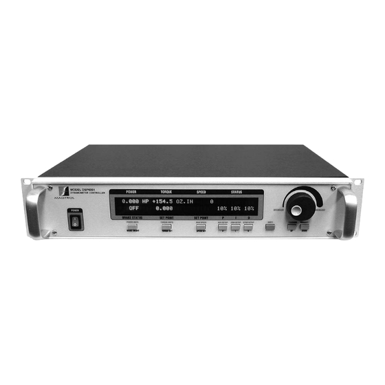
High Speed Programmable Dynamometer Controller
Brand:
Magtrol
| Category:
Controller
| Size: 4 MB
Table of Contents
Safety Precautions
3
Revisions to this Manual
4
Revision Date
4
Table of Revisions
4
Table of Contents
5
Table of Contents
6
Table of Figures
9
Preface
11
Purpose of this Manual
11
Who Should Use this Manual
11
Manual Organization
11
Installation/Configuration
11
Conventions Used in this Manual
12
Introduction
13
Unpacking Your Dsp6001
13
New Features of the Dsp6001
13
Data Sheet
14
2 Controls
20
Controls
20
Front Panel
20
Front Panel Controls and Buttons
20
Enabling Secondary Functions
20
Figure 2-1 Front Panel
20
Figure 2-2 Secondary Function Menu
20
Enabling Saving Function
21
How to Use Front Panel Controls and Buttons
21
Figure 2-3 Saving Function Menu
21
Vacuum Fluorescent Display (Vfd)
22
Contrast Settings
23
Screen Saver
23
Status Display Messages
23
Rear Panel
24
Rear Panel Inputs and Outputs
24
Figure 2-4 Rear Panel
24
Figure 2-5 Dynamometer Brake Input
24
Figure 2-6 Accessory Torque-Speed Output
24
Figure 2-7 Dynamometer/Tsc1 Connector
25
Figure 2-8 AUX/TSC2 Connector
25
Figure 2-9 Supply 1 Connector
25
Figure 2-10 Supply 2 Connector
26
Figure 2-11 RS-232C Interface
26
Installation/Configuration
27
Powering up the Dsp6001
27
Setting Unit for Line Voltage
27
Figure 3-1 Cover for Voltage Selector, Fuses
27
Self-Test
28
Main Menu
28
Figure 3-2 Program Download Display
28
Figure 3-3 Revision Display
28
Figure 3-4 Alarm Warning Display
28
Figure 3-5 Main Menu
28
Testing Instrumentation Setup
29
Dynamometer Configuration Menu
30
Figure 3-6 Dyno Setup Menu
30
Figure 3-7 Dynamometer Configuration Menu
30
Hysteresis Dynamometer Setup
31
Figure 3-8 Hysteresis Dynamometer Setup
31
Figure 3-9 Hysteresis Setup Menu
31
Hysteresis Dynamometer with Torque Transducer Setup
32
Figure 3-10 Hysteresis Dynamometer with Torque Transducer Setup
32
Figure 3-11 Torque Transducer Setup Menu
33
Figure 3-12 aux Setup Menu - Display on
33
Figure 3-13 TSC1 with TM2XX Output Menu
33
Hysteresis Dynamometer with Auxiliary Instrumentation Setup
34
Figure 3-14 Hysteresis Dynamometer with Auxiliary Instrumentation Setup
34
Figure 3-15 TSC2 aux Setup Menu
35
Figure 3-16 TSC1 with aux Output Menu
35
Hysteresis Dynamometer with Eddy-Current or Powder Brake Setup
36
Figure 3-17 Hysteresis Dynamometer with Eddy-Current or Powder Brake Setup
36
Figure 3-18 TSC2 Eddy-Current/Powder Brake Setup Menu
37
Figure 3-19 Nominal Speed Setup Menu
37
Eddy-Current or Powder Brake Dynamometer Setup
38
Figure 3-20 Eddy-Current or Powder Brake Dynamometer Setup
38
Figure 3-21 TSC1 Eddy-Current/Powder Brake Setup Menu
38
Eddy-Current or Powder Brake Dynamometer with Torque Transducer Setup
39
Figure 3-22 Eddy-Current or Powder Brake Dynamometer with Torque Transducer Setup
39
Eddy-Current or Powder Brake Dynamometer with Auxiliary Instrumentation Setup
40
Figure 3-23 Eddy-Current or Powder Brake Dynamometer with Auxiliary Instrumentation Setup
40
Two Eddy-Current/Powder Brake Dynamometers (Independent Setup)
41
Figure 3-24 Two Eddy-Current/Powder Brake Dynamometers (Independent Setup)
41
Figure 3-25 Tandem Configuration Menu
42
Two Eddy-Current/Powder Brake Dynamometers (Tandem Setup)
43
Figure 3-26 Two Eddy-Current/Powder Brake Dynamometers (Tandem Setup)
43
Eddy-Current Dynamometer with Powder Brake Dynamometer (Tandem Setup)
45
Figure 3-27 Eddy-Current Dynamometer with Powder Brake Dynamometer (Tandem Setup)
45
Figure 3-28 TSC1 Eddy-Current Setup Menu
45
Figure 3-29 TSC2 Powder Brake Setup Menu
46
Figure 3-30 Maximum Speed Excited Menu
46
In-Line Torque Transducer Cross Loop Function
47
Figure 3-31 In-Line Torque Transducer Cross Loop Function
47
Figure 3-32 Brake Type Menu
47
Speed Encoder Setup
48
Bit Configurations
48
Figure 3-33 Brake Type Menu (for WB)
48
Figure 3-34 Encoder Menu
48
Torque/Speed Analog Outputs
49
Torque DAC Scale Factor
49
Speed DAC Scale Factor
49
Torque/Speed DAC Setup
49
Figure 3-35 Torque/Speed DAC Setup Menu
49
Digital Filters
50
Filter Parameters
50
Figure 4-1 Transposed Direct Form II Architecture
50
Filter Setup
51
Digital Filters
51
Pid Settings
52
About the Pid Loop
52
P (Proportional Gain)
52
I (Integral)
52
D (Derivative)
52
Setting Pid Values
52
How to Set P (Proportional Gain) Value
52
How to Set I (Integral) Value
52
How to Set D (Derivative) Value
52
How the Pid Loop Works
53
Scale Factors for Hysteresis, Eddy-Current and Powder Brake Dynamometers
53
Speed Correction for WB (Eddy-Current Brake) Dynamometer
53
Pid Settings
53
Figure 5-1 System Block Diagram
53
Equations
54
Additional Scale Factor
54
How to Set Additional Scale Factor
54
P (Proportional Gain)
54
Setting the Correct Pid's for Your Motor
55
Figure 5-2 Open Loop Control Menu
55
Setting the PID for Torque Control
55
Setting the PID with an Unknown Motor or System
55
Figure 5-3 Initial P Setting for Torque Control at 25
56
Figure 5–4 High Initial P Setting for Torque Control
56
Figure 5–5 Initial I Setting for Torque Control
57
Setting the PID for Speed Control
58
Figure 5–8 Initial I Setting for Speed Control
59
Figure 5–10 Ramp down Low I
60
Setting the PID for Ramp down
60
Figure 5–11 Ramp down High I
61
Alar M System
62
General Information
62
Alarm Relay
62
Alarm Operation
63
Figure 6–3 Typical Application
63
Alarm Priority
64
Power Alarm
64
Instructions for Power Alarm Setup
64
Power Alarm Action
65
To Reset Power Alarm
65
Maximum Speed Alarm
65
Instructions for Maximum Speed Alarm Setup
65
Maximum Speed Alarm Action
66
To Reset Maximum Speed Alarm
66
Maximum Torque Alarm
66
Instructions for Maximum Torque Alarm Setup
66
Maximum Torque Alarm Action
67
To Reset Maximum Torque Alarm
67
Air Flow Alarm
68
Instructions for Air Flow Alarm Setup
68
Air Flow Alarm Action
68
To Reset Air Flow Alarm
68
Water Flow Alarm
69
Instructions for Water Flow Alarm Setup
69
Water Flow Alarm Action
69
To Reset Water Flow Alarm
69
External Alarm
70
Instructions for External Alarm Setup
70
External Alarm Action
70
To Reset External Alarm
70
Temperature Alarm
71
Instructions for Temperature Alarm Setup
71
Temperature Alarm Action
71
To Reset Temperature Alarm
71
Electrical Alarm
72
Instructions for Electrical Alarm Setup
72
Electrical Alarm Action
72
To Reset Electrical Alarm
72
Manually Controlled Operation
73
How to Choose Desired Channel When Using Two Dynamometers
73
How to Set Desired Power Units
74
How to Set Desired Torque Units
74
How to Set Torque Control
74
How to Set Speed Control
75
How to Set Open Loop Control
76
Computer Controlled Operation
77
About the Gpib Interface
77
Installing the GPIB (IEEE-488) Connector Cable
77
Changing the GPIB Primary Address
78
About the Rs-232 Interface
78
Connection
78
Communication Parameters
79
Baud Rate
79
Checking the Dsp6001-To-Pc Connection
79
Data Format
80
Programming
80
Data Termination Characters
80
Timeout
81
Dsp6001 Command Set
81
Alarm Commands
81
Communication Commands
82
Ramp Commands
83
Setup Commands
84
Speed Commands
86
Torque Commands
86
Miscellaneous Command
87
Calibration
88
Closed-Box Calibration
88
Calibration Schedule
88
Basic Calibration Process
88
Initial Calibration Procedure
88
TSC1 Offset and Gain
89
Figure 9–1 Calibration Display Analog Inputs
89
TSC2 Offset and Gain
90
DAC Output Offset and Gain
90
Figure 9–5 Supply 1 Connector
91
Speed Check
92
Figure 9–8 Accessory Torque-Speed Output
92
Decimal Point Check
93
10. Troubleshooting
94
Appendix A: Labview Programming Examples
95
Simple Read
95
Torque Stabilized
96
Speed Stabilized
97
Appendix B: Inertia Correction
98
Inertial Effect on Motor Test Data
98
Procedure for Inertia Correction
98
Key Conditions
99
Appendix C: Front Panel/Display Menu Flow Charts
100
Primary Key Functions
100
Secondary Key Functions
101
Power Units Menu
101
Torque Units Menu
101
Max Speed Menu
102
Aux Setup Menu
102
Com Setup Menu
103
C.2.5 Com Setup Menu
103
Dyno Setup Menu
104
Appendix D: Remote Configuration Flow Charts
113
Advanced Configuration
113
Pre-Test
114
Ramp
115
Speed
116
Torque
117
Miscellaneous
118
Data
118
Appendix E: Schematics
119
Dynamometer Power Supply
119
Dynamometer Dsp & Memory
120
Dsp Dynamometer Analog I/O
121
Appendix F: Additional Scale Factor Table
122
Index
123
Advertisement
Advertisement
Related Products
Magtrol DSP6000
Magtrol DSP7000
Magtrol DES 410
Magtrol DES 411
Magtrol 4619
Magtrol 6200
Magtrol AN 2000 C
Magtrol AN Series
Magtrol Categories
Measuring Instruments
Controller
Power Supply
Transducer
Monitor
More Magtrol Manuals
Login
Sign In
OR
Sign in with Facebook
Sign in with Google
Upload manual
Upload from disk
Upload from URL