Sign In
Upload
Manuals
Brands
LinMot Manuals
Servo Drives
C1251-MI-XC-2S-0E Series
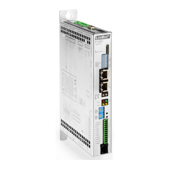
LinMot C1251-MI-XC-2S-0E Series Manuals
Manuals and User Guides for LinMot C1251-MI-XC-2S-0E Series. We have
1
LinMot C1251-MI-XC-2S-0E Series manual available for free PDF download: Manual
LinMot C1251-MI-XC-2S-0E Series Manual (150 pages)
Brand:
LinMot
| Category:
Servo Drives
| Size: 5.73 MB
Table of Contents
Table of Contents
3
Scope
13
Objective
13
Purpose of Document
13
Applicable Documents
13
Referenced Documents
13
Table 1: Applicable Documents
13
Table 2: Referenced Documents
13
Introduction / Preface
14
Legal Notices
14
Warning Concept
14
Proper Use of Linmot Products
14
Read the Documentation
15
Qualified Personnel
15
Intended Use
15
Prohibited Use
15
Brands
16
Non-Safety Function
16
Disclaimer
16
Preface
16
Technical Support Contacts
16
Target Group
16
Benefits
16
Standard Scope
16
Standards and Regulations
17
Aims
17
Functional Safety
17
Considered Standards
18
Country Specific Regulations
18
Fundamental Safety Instructions
19
General Safety Instructions
19
Liability
19
Industrial Security
20
General Safety Notes Linmot Products
21
Products and Life Cycles
21
Overview Life Cycle, Safety Notes and Products
22
Table 3 Life Cycle and Safety Notes
22
Safety Notes
23
Fundamental Safety Instructions
29
Residual Risk
31
Linmot Safety Products
32
Figure 1: Linmot-System
32
Drives
33
Table 4: Supported Drives
33
Table 5: Drive Nomenclature
33
Supported Safety Functions
34
Safety Relevant Drive Installation Instructions
34
Physical Dimensions, Mounting, Environment
34
Figure 2: Drive Physical Dimension
34
Table 6: Drive Physical Dimension, Mounting and Environment
35
Supply and Grounding
36
Signal Power Supply
36
Figure 3: Supply and Grounding
36
Motor Power Supply
37
Regeneration
37
Connectors and Wiring
37
PE: Protective Earth
37
Table 7: PE Connector: Protective Earth
37
X1: Motor Supply
38
X2/X3: Motor Connection
38
Table 8: X1 Connector: Motor Supply
38
Table 9: X3 Connector: Motor Sensor / Non Safe Brake
39
X4: Logic Supply / IO Connection
40
X17 - X18: Real Time Ethernet 10/100 Mbit/S
40
Table 10: X4 Connector: Logic Supply / IO Connection
40
Table 11: X17/X18 Real Time Ethernet 10/100 Mbit/S
40
X19: System
41
X49: Safe Digital IO
41
Table 12: X19: System
41
Table 1213: X49 Connector: Safe Digital IO
41
X50 Safe Brake
42
Table 14: X50 Connector. Safe Brake
42
Drive Ordering Information
43
Table 15: Drive Ordering Information
43
Motors
44
Figure 4: Motor (Stator and Slider)
44
Table 16: Supported Motors and Ordering Information
44
Environmental Conditions for Motors
45
Stators
45
Stator Nomenclature
45
Table 17: Environmental Conditions for Motors
45
Table 18: PS01 Stator Nomenclature
45
Sliders
46
Slider Nomenclature
46
Table 19: Pl0X Slider Nomenclature
46
Motor Cable
47
Table 20: Cable List
47
Rotatability of Motor Connectors
48
Figure 5: Rotatability of Motor Connectors
48
Safety Functions
49
Safety Functions Overview and Compatibility
49
Table 21: List of Safety Functions and Combination with Safe/Non-Safe Encoders
49
General Safety Information
50
Boundary of the Safety Compliant System
50
Constraints of the Use of the Safety Compliant System
50
Safety Characteristics for All Safety Functions
51
Failure Modes
51
Table 22 : Characteristics of Safety Functions According to IEC 61508
51
Table 23: Characteristics of Safety Functions According to /ISO13849-1
51
Implemented Measures against Systematic Errors
52
Used Technologies and Architecture
52
Figure 6: Safety Related Block Diagram
52
Regarded Safety Related Errors Taken Measures
53
Table 24: Regarded Safety Related Errors and Taken Measures
54
Periodic Proof Tests
55
Table 25: Periodic Proof Tests
55
Error Reaction Times
56
System Reaction Times
56
Table 26: Error Reaction Times
56
Table 27: System Reaction Times
56
Predictable User Errors
57
Table 28: Predictable User Errors and Measures
57
Data Types
58
Access and Visibility to Parameters and Variables
58
Figure 7: Linmot-Talk Login Mask
58
Table 29: Data Types for Parameters and Variables
58
Safety Parameters Overview
59
Configure Safety Parameters
59
Figure 8: Schematics of a Safe Digital Input (One Channel)
59
Setting the Safety Parameters
60
Figure 9: Changing Safety Parameters
60
Figure 10: Changed Safety Parameter
60
Validate the Safety Parameters
61
Login
61
Figure 11: Start Safety Parameter Validation
61
Figure 12: Login for Safety Parameter Validation
61
Verify Groups
62
Read ASCII Report
62
Figure 13: Verify Safety Parameter Groups
62
Figure 14: ASCII Report
62
Print ASCII Report
63
Validate Parameters
63
Safety Parameter Checksum
63
Figure 15: Validate Parameters
63
Figure 16: Status Message on Validation End
63
Flash Card (FC)
64
Table 30: Flash Card List
64
Table 31: Commands Called by ID Switches S1/S2
64
Default All Parameters
65
Table 32: Commands Called by the Safe Address Switches S11/S12
65
Table 33: Default All Parameters
65
Save All Parameters to FC with Linmot-Talk
66
Save All Parameters to FC Via ID Switches
67
Table 34: Safe All Parameters to FC
67
Load Non-Safety Parameters from the FC
68
Table 35: Load Non-Safe Parameters from the FC
68
Load and Validate All Parameters from the FC
69
Table 36: Load Complete Parameters from the FC and Validate the Safety Parameter
71
Safety Variables and Monitoring
72
Figure 17: Safety Module Variables
72
Table 37: Safety Module Variables
72
Figure 18: Safety Variables and States
73
Table 38: HW STO Feedback Signals
73
Table 39: Safety System States
74
Table 40: Safety Error States
74
Table 41: Safety Board Error Codes States
76
Table 42: Safety IO States
77
Table 43: Safety Function States
80
Table 44: Safe Velocity and Position
81
Table 45: SBT Monitoring
82
Figure 19: Safety State Diagram
83
Table 46: Failure Classification and Reaction
86
Table 47: General Settings Parameters
87
Figure 20: Schematics of a Safe Digital Input (One Channel)
92
Figure 21: Schematics of the Acknowledge Input
93
Figure 22: Schematics of the Safe Digital Output (One Channel)
95
Figure 23: STO Timing
97
Figure 26: SBT Oscilloscope Shot
112
Figure 27: SS1 Timing
113
Figure 28: SOS Timing
118
Figure 29: SS2 Timing
123
Figure 30: SLS Timing
127
Figure 31: SLS Oscilloscope Shot: this Shot Shows the Margin of the Safety Velocity
132
Figure 32: Safety Module Values
139
Advertisement
Advertisement
Related Products
LinMot C1251-MI-XC-2 0E Series
LinMot C1251-MI-XC-2S Series
LinMot C1251-MI-XC-2S-0E-000
LinMot C1251-MI-XC-2S-0E-C00
LinMot C1251-2S
LinMot C1250-PL-XC-0S-000
LinMot C1250-PN-UC
LinMot C1250-MI
LinMot C1250-CM-XC S Series
LinMot C1250-DS-XC-0S-C00
LinMot Categories
Engine
Servo Drives
Controller
DC Drives
Control Unit
More LinMot Manuals
Login
Sign In
OR
Sign in with Facebook
Sign in with Google
Upload manual
Upload from disk
Upload from URL