Sign In
Upload
Manuals
Brands
Lenze Manuals
DC Drives
8200 vector
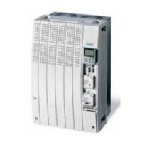
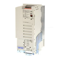
Lenze 8200 vector Manuals
Manuals and User Guides for Lenze 8200 vector. We have
9
Lenze 8200 vector manuals available for free PDF download: System Manual, Manual, Operating Instructions Manual, Mounting Instructions, Getting Started
Lenze 8200 vector System Manual (588 pages)
0.25 kW...90 kW
Brand:
Lenze
| Category:
DC Drives
| Size: 12 MB
Table of Contents
1 Preface
3
Table of Contents
3
The 8200 Vector Frequency Inverter
5
How to Use this System Manual
7
Information Provided by the System Manual
7
Products to Which the System Manual Applies
8
Legal Regulations
9
Section 2
11
Glossary
13
Terminology and Abbreviations Used
13
Meaning of the Signal Names
14
Total Index
23
Section 3
33
List of Illustrations
33
4 Technical Data
53
General Data/Application Conditions
55
Operation with Rated Power (Normal Operation)
59
Rated Data for Mains Voltage 230 V
59
Rated Data for Mains Voltage 400 V
59
Rated Data for Mains Voltage 500 V
60
Rated Data for Mains Voltage 230 V
61
Mains Voltage 500 V
72
5 Basic Device Installation
83
Important Notes
85
Basic Units in the Power Range 0.25
87
Mounting with Fixing Rails (Standard)
87
Basic Units in the Power Range 3
88
Fig. 5.3-2 Dimensions for Thermally Separated Mounting 0.25
88
Thermally Separated Mounting (Push-Through Technique)
88
Fig. 5.3-3 Thermally Separated Mounting 0.25
89
Fig. 5.3-4 Dimensions for Thermally Separated Mounting 1.5
90
Fig. 5.3-5 Thermally Separated Mounting 1.5
91
Fig. 5.3-6 Dimensions for Mounting in "Cold Plate" Technique 0.25
93
Fig. 5.3-7 DIN Rail Mounting 0.25
94
Fig. 5.3-8 Fixed Lateral Mounting
95
Fig. 5.3-9 Swivelling Lateral Mounting
96
Fig. 5.4-1 Standard Mounting with Fixing Rails 3
97
Mounting with Fixing Rails (Standard)
97
Fig. 5.4-2 Dimensions for Thermally Separated Mounting 3
98
Thermally Separated Mounting (Push-Through Technique)
98
Fig. 5.4-3 Dimensions for Thermally Separated Mounting Cutout 3
99
Fig. 5.4-4 Dimensions for Mounting in "Cold Plate" Technique 3
101
Fig. 5.4-5 Fixed Lateral Mounting
102
Fig. 5.4-6 Swivelling Lateral Mounting
103
Basic Units in the Power Range 15
105
Mounting with Fixing Brackets and Mains Choke (Standard)
105
Fig. 5.5-1 Standard Mounting with Mains Choke 15
105
Fig. 5.5-2 Standard Mounting with Footprint Mains Filter 15
106
Mounting with Fixing Brackets and Footprint Mains Filter
106
Fig. 5.5-3 Standard Mounting with Built-On Mains Filter 15
107
Mounting with Fixing Brackets and Built-On Mains Filter
107
Fig. 5.5-4 Dimensions for Thermally Separated Mounting 15
108
Thermally Separated Mounting (Push-Through Technique)
108
Mounting in "Cold Plate" Technique
109
Fig. 5.5-5 Dimensions for 8200 Vector in "Cold Plate" Technique 15
110
Fig. 5.5-6 Dimensions for 8200 Vector in "Cold Plate" Technique 15
111
Basic Units in the Power Range 45
113
Fig. 5.6-2 Standard Mounting with Footprint Mains Filter 45
114
Fig. 5.6-3 Standard Mounting with Built-On Mains Filter
115
Fig. 5.6-4 Dimensions for Thermally Separated Mounting 45
116
Mounting with Fixing Brackets and Mains Choke (Standard)
117
Basic Units in the Power Range 75
117
Fig. 5.7-2 Standard Mounting with Footprint Mains Filter 75
118
Mounting with Fixing Brackets and Footprint Mains Filter
118
Mounting with Fixing Brackets and Built-On Mains Filter (Mounting Variant 1)
119
Fig. 5.7-4 Standard Mounting with Built-On Mains Filter 75
120
Mounting with Fixing Brackets and Built-On Mains Filter (Mounting Variant 2)
120
Fig. 5.7-5 Dimensions for Thermally Separated Mounting 75
121
Thermally Separated Mounting (Push-Through Technique)
121
6.1 6 Basic Unit Wiring
123
Important Notes
125
Protection of Persons
125
Motor Protection
126
Mains Types/Mains Conditions
126
Operation on Public Mains (Compliance with en 61000-3-2)
127
Operation with E.l.C.bs (Earth-Leakage Circuit-Breakers)
128
Interactions with Compensation Equipment
128
Specification of Cables Used
129
Fig. 6.2-1 Wiring of the Terminal Strips
130
Wiring of Terminal Strips
130
Basics for Wiring According to EMC
131
Requirements on the Cables
131
Fig. 6.3-1 Shielding of the Motor Cable
132
Shielding
132
Fig. 6.3-2 Shielding of Long, Analog Control Cables
133
Installation in the Control Cabinet
133
Fig. 6.3-3 Cable Routing in the Control Cabinet
135
Fig. 6.3-4 Cable Routing in the Cable Duct with Barrier
136
Fig. 6.3-5 Cable Routing in Separated Cable Ducts
136
Wiring Outside the Control Cabinet
136
Basic Units in the Power Range 0.25
139
Basic Units in the Power Range 15
139
Wiring According to EMC (Installation of a CE-Typical Drive System)
140
Basic Units in the Power Range 45
141
Fig. 6.4-2 Mains Connection 230/240 V 0.25
142
Power Connections for 230 V Mains Voltage
142
Fig. 6.4-3 Mains Connection 400/500 V 0.55
143
Power Connections for 400 V Mains Voltage
143
Fig. 6.4-4 Motor Connection 0.25
144
Relay Output Connection
145
Basic Units in the Power Range 3
147
Basic Units in the Power Range 45
147
Wiring According to EMC (Installation of a CE-Typical Drive System)
148
Fig. 6.5-2 Mains Connection 230/240 V 3
150
Power Connections for 230 V Mains Voltage
150
Power Connections for 400 V Mains Voltage
151
Fig. 6.5-4 Motor Connection 3
152
Relay Output Connection
153
Fig. 6.6-1 Wiring According to EMC Requirements 15
156
Fig. 6.6-2 Mains Connection 15
158
Power Connections
158
Fig. 6.6-4 Relay Connections K1 and K2
160
Connection of Relay Outputs K1 and K2
160
Fig. 6.7-1 Wiring According to EMC Requirements 15
164
Fig. 6.7-2 Mains Connection 45
166
Fig. 6.7-3 Motor Connection 45
167
Fig. 6.7-4 Relay Connections K1 and K2
168
Basic Units in the Power Range 75
171
Fig. 6.8-1 Wiring According to EMC Requirements 15
172
Wiring According to EMC (Installation of a CE-Typical Drive System)
172
Fig. 6.8-2 Mains Connection 75
174
Power Connections
174
Fig. 6.8-3 Motor Connection 75
175
Fig. 6.8-4 Relay Connections K1 and K2
176
Connection of Relay Outputs K1 and K2
176
7.1 7 Extensions for Automation
179
Basic Units in the Power Range 0.25
181
Function Modules
181
Fig. 7.2-1 Worksteps
181
Fig. 7.2-2 Additional Worksteps
182
Fig. 7.2-3 Worksteps
182
Fig. 7.2-4 Additional Worksteps
183
Fig. 7.2-5 Front and Rear View
184
Terminal Assignment - Standard I/O E82ZAFSC
184
Terminal Assignment - Standard I/O PT E82ZAFS010
188
Fig. 7.2-7 Front and Rear View
189
Terminal Assignment - Application I/O E82ZAFA
189
Terminal Assignment - Application I/O PT E82ZAFA
189
Fig. 7.2-8 Wiring at Internal /External Supply
192
Bus Function Modules
194
Communication Modules
195
Basic Units in the Power Range 3
197
Function Modules
197
Fig. 7.3-1 Worksteps
197
Fig. 7.3-2 Additional Worksteps
198
Fig. 7.3-3 Worksteps
198
Fig. 7.3-4 Additional Worksteps
199
Fig. 7.3-5 Front and Rear View
200
Terminal Assignment - Standard I/O E82ZAFSC
200
Terminal Assignment - Standard I/O PT E82ZAFS010
204
Fig. 7.3-7 Front and Rear View
205
Terminal Assignment - Application I/O E82ZAFA
205
Fig. 7.3-8 Wiring at Internal /External Supply
208
Terminal Assignment - Application I/O PT E82ZAFA
209
Bus Function Modules
210
Communication Modules
211
Fig. 7.3-10 Relay KSR
213
Connection of Relay Output KSR for "Safe Standstill
213
Basic Units in the Power Range of 15
215
Function Modules
215
Fig. 7.4-1 Worksteps for the Basic Devices 15
216
Wiring of the Terminals "Controller Inhibit (CINH)
216
Fig. 7.4-3 Front and Rear View
218
Fig. 7.4-5 Front and Rear View
223
Fig. 7.4-6 Wiring at Internal /External Supply
226
Fig. 7.4-7 Wiring of the Controller Inhibit with Internal Voltage Supply
228
Fig. 7.4-8 Wiring of the Controller Inhibit with External Voltage Supply
228
Bus Function Modules
229
Fig. 7.4-9 Mounting/Dismounting of the Communication Module
230
Communication Modules
230
Connection of Relay Output KSR for "Safe Standstill
231
Fig. 7.4-10 Relay Connection "Safe Standstill" 15
232
8 Commissioning
233
Before Switching on
235
Fig. 8.3-1 Comparison of V/F Characteristic Control and Vector Control
237
Selection of the Control Mode
237
Parameter Setting with the E82ZBC Keypad
239
V/F Characteristic Control
243
Parameter Setting with the XT EMZ9371BC Keypad
243
Vector Control
244
Important Codes for Quick Commissioning
248
9 Parameter Setting
253
Important Notes
255
Parameter Setting with the E82ZBC Keypad
257
General Data and Application Conditions
257
Fig. 9.3-1 Installation and Commissioning of the E82ZBC Keypad or
258
Installation and Commissioning
258
Fig. 9.3-2 Display Elements and Function Keys of the E82ZBC Keypad
259
Fig. 9.4-1 Installation and Commissioning of XT EMZ9371BC Keypad or
270
Fig. 9.4-2 Display Elements and Function Keys of the XT EMZ9371BC Keypad
270
Installation and Commissioning
270
Display Elements and Function Keys
270
Changing and Saving Parameters
273
Transfer Parameters to Other Controllers
274
Activation of Password Protection
276
Remote Parameter Setting for System Bus Participants
277
Menu Structure
277
Parameter Setting with the XT EMZ9371BC Keypad
277
Menu Structure
278
10.1 10 Function Library
285
Contents
286
Important Notes
287
Fig. 10.3-1 Comparison of V/F Characteristic Control and Vector Control
289
Operating Mode
289
V/F Characteristic Control
289
Vector Control
289
Fig. 10.3-2 Linear and Square-Low V/F Characteristic
291
Sensorless Torque Control with Speed Limitation
292
Fig. 10.3-3 Umin Boost at Linear and Square-Law V/F Characteristic
295
Optimising the Operating Behaviour
303
Slip Compensation
303
Inverter Chopper Frequency
305
Oscillation Damping
306
Behaviour in the Event of Mains Switching, Mains Failure or Controller Inhibit
311
Start Conditions/Flying-Restart Circuit
311
Controller Inhibit
311
Controlled Deceleration after Mains Failure/Mains Disconnection
314
Fig. 10.6-1 Relation between Setpoint and Minimum and Maximum Output Frequency
317
Limit Value Setting
317
Speed Range
317
Current Limits
319
Acceleration, Deceleration, Braking, Stopping
322
Fig. 10.7-1 Acceleration Times and Deceleration Times for Linear Ramp Function Generator
322
Fig. 10.7-2 Acceleration Times and Deceleration Times for Linear Ramp Function Generator
323
Quick Stop
324
Change of Direction of Rotation
325
DC Braking (DCB)
326
AC Motor Braking
328
Configuration of Analog and Digital Setpoints and Actual Values
331
Setpoint Source Selection
331
Fig. 10.8-1 Gain and Offset at Unipolar Setpoint Selection
336
Fig. 10.8-2 Gain and Offset at Bipolar Setpoint Selection
336
Fig. 10.8-3 Gain and Offset at Inverse Setpoint Selection
337
Fig. 10.8-4 Calculation Example for Gain and Offset
337
Digital Setpoints Via Frequency Input
339
Setpoints Via Function "Motor Potentiometer
341
Fig. 10.8-5 Motor Potentiometer with NC Contacts
342
Setpoints Via Keypad
345
Setpoints Via a Bus System
346
Setpoint Changeover (Hand/Remote Changeover)
348
Fig. 10.10-1 Example: Dancer Control with Adding Influence of the Process Controller
353
Fig. 10.10-2 Example: Dancer Control with Subtractive Influence of the Process Controller
354
Fig. 10.12-1 Output Signal of the Function "1/Output Frequency
369
11 Troubleshooting and Fault Elimination
459
Troubleshooting
461
Status Display (Led's on the Controller)
461
Error Analysis with the History Buffer
461
Drive Performance in Case of Errors
463
Error Elimination
465
Maloperation of the Drive
465
Error Messages at the Keypad or in the Parameter Setting Program Global Drive Control
466
Resetting Error Messages
469
12 Network of Several Drives
471
General Information
473
Function
475
Conditions for a Trouble-Free Network of Several Drives
477
Possible Combinations of Lenze Controllers in a Network of Several Drives
477
Mains Connection
478
Fig. 12.4-1 Decentralised Switching of the Mains Supply in Network Operation
479
Fig. 12.4-2 Example: DC Connection of Three Controllers
480
DC-Bus Connection
480
Fuses and Cable Cross-Sections for a Network of Several Drives
482
Protection in DC-Bus Operation
484
Selection
487
Conditions
487
Required Mains Filters or Mains Chokes
488
Supplies - 230 V Controller
489
Supplies - 400 V Controllers
490
Selection Examples
491
Fig. 12.5-1 Example with Two Simultaneously Accelerated and Decelerated Drives
495
Fig. 12.5-2 Example with Two Not Simulateneously Accelerated or Decelerated Drives
495
Central Supply (One Supply Terminal)
497
Central Supply Via External DC Source
497
Fig. 12.6-2 Network of 400 V Controllers with Central Supply
498
Central Supply 400 V with Regenerative Power Supply Unit 934X
498
Decentralised Supply (Several Supply Terminals)
499
Decentralised Supply with Single-Phase or Two-Phase Mains Connection
499
Decentralised Supply with Three-Phase Mains Connection
500
Braking Operation in a Drive System
501
Possibilities
501
Selection
502
13 Braking Operation
503
Braking Operation
505
Braking Operation Without Additional Measures
505
Braking Operation with Three-Phase AC Brake Motor
507
Braking Operation with External Brake Resistor
511
8200 Vector 0.25
512
8200 Vector 15
515
Selection of the Brake Resistors
518
Rating for Lenze Brake Resistors
519
Wiring of Brake Resistor
520
15 Application Examples
525
Pressure Control
527
Fig. 15.2-1 Principle Wiring of a Pressure Regulation
530
Operation with Medium-Frequency Motors
531
Dancer Position Control (Linear Drive)
533
Fig. 15.4-1 Principle Wiring of a Dancer Position Control
534
Fig. 15.5-1 Speed Control with 3-Conductor Sensor
535
Speed Control
535
Fig. 15.6-1 Basic Structure of a Group Drive
541
Group Drive (Operation with Several Motors)
541
Sequential Circuit
543
Fig. 15.8-1 Principle of Setpoint Summation
545
Setpoint Summation (Basic and Additional Load Operation)
545
Power Control (Torque Limitation)
547
Fig. 15.9-1 Power Control Principle Example: Fan
548
Advertisement
Lenze
8200
Manual
Lenze 8200 vector Manual (313 pages)
Global Drive
Brand:
Lenze
| Category:
DC Drives
| Size: 2 MB
Table of Contents
Table of Contents
6
Edition of
17
1 Preface and General Information
18
How to Use this Manual
18
Terminology Used
18
Scope of Delivery
18
Legal Regulations
20
EC Directives/Declaration of Conformity
21
What Is the Purpose of EC Directives
21
What Does the CE Mark Imply
21
EC Low-Voltage Directive
22
EC Directive Electromagnetic Compatibility
24
EC Machinery Directive
28
2 Safety Information
30
General Safety Information
30
Layout of the Safety Information
31
Residual Hazards
31
Part B
32
3 Technical Data
34
Overview of Types
34
Features
35
General Data/Application Conditions
37
Rated Data (Operation with 150 % Overload)
38
Types 8201 to 8204
38
Types 8211 to 8214
39
Types 8215 to 8218
41
Types 8221 to 8224
43
Types 8225 to 8227
45
Types 8241 to 8243
47
Types 8244 to 8246
49
Rated Data (Operation with 120 % Overload)
51
Types 822X
52
Types 824X
53
Fuses and Cable Cross-Sections
54
Protection of the Motor Cables
54
Single Drives with 150 % Overload
55
Single Drives with 120 % Overload
56
Analog Plug-In Module 8279IB
57
Features
57
Dimensions
58
Analog Plug-In Module
58
4 Installation
59
Mechanical Installation
59
Important Notes
59
Standard Assembly with Fixing Rails or Fixing Brackets
61
Type 8202-V002 (Reduced Assembly Depth)
61
Types 8201 to 8204
61
Types 8211 to 8214
62
Types 8215 to 8218
63
Types 8221 to 8227
64
Types 8241 to 8246
65
DIN-Rail Assembly
66
Types 8201 to 8204
66
Types 8211 to 8214
67
Assembly with Thermally Separated Power Stage
68
("Push-Through Technique")
68
Types 8215 to 8218
69
Types 8221 to 8227
70
Types 8241 to 8246
71
Assembly of the Variant 82XX-V003 "Cold Plate
72
General
72
Demands on the Cooler
73
Thermal Performance of the System
74
Assembly Preparations
75
Assembly of 821X-C-V003
76
Assembly of 822X-C-V003
79
Assembly of 824X-C-V003
80
Assembly with Mains Filter
81
Assembly of the Analog Plug-In Module 8279IB
82
Electrical Installation
83
Operator's Safety
83
Protection of the Controllers
84
Motor Protection
84
Mains Types/Mains Conditions
85
Combination with Compensation Equipment
85
Specification of the Cables Used
85
Power Connections
86
Mains Connection
86
Motor Connection
87
Connection of a Brake Unit
92
Connection Plan 820X
93
Connection Plan 821X
94
Connection Plan 822X/824X
95
Control Connections
96
Assignment of the Control Terminals
96
Control Cables
96
Connection Diagrams
99
Connection Diagrams: Analog Plug-In Module
100
Installation of a CE-Typical Drive System
101
5 Commissioning
107
Short Commissioning (Factory Setting)
108
Adapt Machine Data
109
Optimisation of the Operating Behaviour
112
Optimising Operating Modes
114
Display Values
121
Operation with PID Controller
122
Application Examples
124
Pump Application with Level Control
127
Dancer-Position Control (Line Drive)
129
Air Conditioning System
132
6 During Operation
135
Operating Information
135
Display of the Controller Status
136
Monitoring Functions
139
7 Configuration
140
8201BB Operating Module
140
Structure of the Operating Program
142
Operating Level
142
Code Level
142
Parameter Level
142
Change and Store Parameters
143
Change and Store Parameters with the 8201BB Operating Module
144
Change and Store Parameters with Fieldbus Modules
146
Dynamic Parameter Change
146
Operating Functions
147
Operating Mode
147
Working with Parameter Sets
148
Change Parameter Set Via DC-Bus Voltage
150
AC-Motor Braking by Means of Parameter Set Changeover
150
Deceleration in the Event of Mains Failure
151
Control Functions
153
Speed Range (Fdmin, Fdmax)
153
Current Limit Values (Imax Limit Values)
155
Current Limitation Controller (Imax Controller)
156
Control Mode
157
V/F Characteristic
160
V/F-Rated Frequency Fdr
160
Configuration
160
Motor Data Detection
165
Running Optimisation
166
Slip Compensation
166
Chopper Frequency
167
Oscillation Damping
169
Ramp Function Generator S-Shape
170
Skip Frequencies
171
PID Controller as Process Controller
172
7.5.10.1 Reset Integral Component and Influence
176
7.5.10.2 Setpoint Selection for the Process Controller
176
7.5.10.3 Frequency Precontrol
177
7.5.10.4 Frequency Setting Range
177
Setpoint Input
178
7.5.11.1 Analog Setpoint Input
178
7.5.11.2 Setpoint Input Using the Keypad
180
7.5.11.3 Setpoint Input Via JOG Frequencies
181
7.5.11.4 Setpoint Input Via Function "Motor Potentiometer
182
Combination with JOG Value
184
7.5.11.6 Setpoint Sum
185
Code Table for "Standard" Series
215
Code Table for "HVAC" Series
223
Display at the Controller
237
Display at the Operating Module
237
Troubleshooting
237
Troubleshooting and Fault Elimination
237
Fault Analysis with the History Buffer
238
Fault Messages
238
Maloperation of the Drive
238
Reset of Fault Messages
240
Maintenance
241
Service Addresses
242
Part F
243
10 Network of Several Drives
245
Function
245
Conditions for Trouble-Free Network Operation
246
Possible Combinations
246
10.2.2.1 Cable Protection/Cable Cross-Section
247
10.2.2.3 Controller Protection
247
Mains Connection
247
DC-Bus Connection
248
Fuses and Cable Cross-Sections for a Network of Several Drives
250
Protection in Networks of Several Drives
251
Conditions
253
Selection Basics
253
10.3.2.1 Supply Only Via Controllers
256
Selection Example for 4 Drives
256
10.3.2.2 Supply by Means of 934X Supply and Feedback Module
257
Central Supply
258
Central Supply of 820X
258
Central Supply Via 934X for 821X/822X/824X/93XX
259
Decentral Supply for 820X
260
Central Supply for 821X/822X/824X/93XX/934X
261
Lenze 8200 vector Operating Instructions Manual (270 pages)
8200 motec frequency inverter 0.25 kW ... 7.5 kW
Brand:
Lenze
| Category:
DC Drives
| Size: 1 MB
Table of Contents
Table of Contents
3
1 Preface and General Information
8
Legal Regulations
9
2 Safety Information
10
General Safety and Application Instructions for Lenze Motors
12
Residual Hazards
14
Technical Data
16
3 Technical Data.
20
Rated Data at a Mains Voltage of 230 V
20
Operation with Increased Rated Power
21
Rated Data at a Mains Voltage of 400/500 V
22
Operation with Increased Rated Power
24
Installation
26
Dimensions
27
Electrical Installation
28
Mains Types/Mains Conditions
29
Operation with Earth−Leakage Circuit Breaker
30
Specification of the Cables Used
31
Installation According to EMC
32
Power Connections
33
Terminal Assignment − Standard I/O E82ZAFSC001
34
Terminal Assignment − Application I/O E82ZAFAC001
37
Wiring of Bus Function Modules
41
5 Commissioning
42
Before You Start
42
Menu Structure
43
Edb82Mv752 en
43
Changing and Saving Parameters
44
Selection of the Correct Control Mode
45
Commissioning − V/F Characteristic Control
47
Commissioning Without Function Module
47
Commissioning with Standard I/O Function Module
49
Commissioning − Vector Control
51
Commissioning Without Function Module
51
Commissioning with Standard I/O Function Module
53
Vector Control Optimisation
55
General Information
56
6 Parameter Setting
56
Parameter Setting Via Keypad
57
Installation/Commissioning
57
Displays and Functions
57
Menu Structure
59
Changing and Saving Parameters Using the Keypad
60
Change Parameter Set
60
Remote Parameterisation of System Bus Nodes
61
Change Entries in the User Menu
61
Activation of Password Protection
62
Parameter Setting Using the LECOM−A (RS232) Communication Module
64
Technical Data
64
General Data/Operating Conditions
64
Communication Times
65
Wiring to a Host (PC or PLC)
66
Notes on Self−Made PC System Cables
66
Parameter Setting Using LECOM−A (RS232)
67
Additional Codes for LECOM−A (RS232)
67
Troubleshooting and Fault Elimination LECOM−A (RS232)
71
7 Function Library
72
Operating Mode
73
V/F Characteristic Control
75
Vector Control
79
Sensorless Torque Control with Speed Limitation
81
Optimising the Operating Behaviour
84
Slip Compensation
84
Inverter Switching Frequency
85
Oscillation Damping
87
Skip Frequencies
88
Behaviour in the Event of Mains Switching, Mains Failure or Controller Inhibit
89
Controlled Deceleration after Mains Failure/Mains Disconnection
90
Controller Inhibit
91
Limit Value Setting
92
Current Limits
94
Acceleration, Deceleration, Braking, Stopping
95
Quick Stop
98
Change of Direction of Rotation
99
DC Braking (DCB)
101
AC Motor Braking
102
Configuration of Analog and Digital Setpoints and Actual Values
103
Analog Setpoints Via Terminal
105
Digital Setpoints Via Frequency Input
110
Setpoints Via Function "Motor Potentiometer"
112
Setpoints Via Fixed Setpoints (JOG)
114
Setpoints Via Keypad
116
Setpoints Via a Bus System
117
Setpoint Changeover (Hand/Remote Changeover)
118
Automatic Detection of Motor Data
119
Process Controller
121
Setpoint Selection for the Process Controller
124
Actual Value Selection for the Process Controller
125
Switching off Process Controller Functions
126
Current−Limit Controller
127
Free Interconnection of Analog Signals
128
Free Configuration of Analog Outputs
130
Free Configuration of Analog Process Data Output Words
135
Free Interconnection of Digital Signals
139
Free Configuration of Digital Outputs
144
Free Configuration of Digital Process Data Output Words
150
Thermal Motor Monitoring
153
Temperature Monitoring of the Motor with PTC and Earth−Fault Detection
155
External Fault Evaluation
156
Display of Operating Data, Diagnostics
157
Diagnostics
160
Parameter Set Management
162
Parameter Set Changeover
165
Individual Summary of Drive Parameters in the User Menu
166
8 Troubleshooting and Fault Elimination
168
Drive Performance in Case of Errors
169
Error Elimination
170
Fault Messages on the Keypad or in the Parameter Setting Program Global Drive Control
171
DC−Bus Connection
172
Resetting Error Messages
174
9 Automation.
176
System Bus Function Module (CAN) E82ZAFC
176
10 Dc−Bus Connection.
180
11 Braking Operation
180
Rated Data of the Integrated Brake Transistor
181
Rated Data of Lenze Brake Resistors
182
12 Accessories.
186
Advertisement
Lenze
8200 vector
Mounting Instructions
Lenze 8200 vector Mounting Instructions (168 pages)
15 kW...90 kW
Brand:
Lenze
| Category:
DC Drives
| Size: 3 MB
Table of Contents
Deutsch
6
Table of Contents
6
1 Sicherheitshinweise
8
Allgemeine Sicherheits- und Anwendungshinweise für Lenze-Antriebsregler
8
Restgefahren
9
Gestaltung der Sicherheitshinweise
9
2 Lieferumfang
10
E82Ev153K4B
10
E82Ev453K4B
11
3 Technische Daten
12
Allgemeine Daten/Einsatzbedingungen
12
Bemessungsdaten
13
Betrieb mit Bemessungsleistung - Normalbetrieb (150 % Überlast)
13
Betrieb mit Erhöhter Bemessungsleistung (120 % Überlast)
13
4 Mechanische Installation
14
Montage E82EV153K4B
14
Befestigungswinkel (Standard) und Netzdrossel
14
Befestigungswinkel (Standard) und Unterbau-Netzfilter
15
Befestigungswinkel (Standard) und Anbau-Netzfilter
16
Montage E82EV453K4B / E82EV553K4B
17
Befestigungswinkel (Standard) und Netzdrossel
17
Befestigungswinkel (Standard) und Unterbau-Netzfilter
18
Befestigungswinkel (Standard) und Anbau-Netzfilter
19
Montage E82EV753K4B / E82EV903K4B
20
Befestigungswinkel (Standard) und Netzdrossel
20
Befestigungswinkel (Standard) und Unterbau-Netzfilter
21
Befestigungswinkel (Standard) und Anbau-Netzfilter (Montagevariante 1)
22
Befestigungswinkel (Standard) und Anbau-Netzfilter (Montagevariante 2)
23
5 Elektrische Installation
24
EMV-Gerechte Verdrahtung (Aufbau des CE-Typischen Antriebssystems)
24
Leistungsanschlüsse E82EV153K4B
25
Netzanschluß
25
Anschluß Motor
26
Leistungsanschlüsse E82EV453K4B / E82EV553K4B
27
Netzanschluß
27
Anschluß Motor
28
Leistungsanschlüsse E82EV753K4B / E82EV903K4B
29
Netzanschluß
29
Anschluß Motor
30
Anschluß Relaisausgänge K1 und K2
31
Anschluß Relaisausgang KSR für "Sicherer Halt
33
6 Funktionsmodule (Option)
34
Montage
34
Verdrahtung der Klemmen "Reglersperre (CINH)" bei Betrieb von Zwei Funktionsmodulen
35
Demontage
36
7 Kommunikationsmodul (Option)
37
Montage/Demontage
37
8 Inbetriebnahme
38
Bevor Sie Beginnen
38
Parametrieren mit dem Keypad
39
Menüstruktur
39
Das Menü User - die 10 Wichtigsten Antriebsparameter auf einen Blick
40
Wechsel zwischen den Menüs User und ALL
41
Parameter in den Menüs Ändern
42
Wahl der Richtigen Betriebsart
43
U/F-Kennliniensteuerung
45
Vector-Regelung
46
Vector-Regelung Optimieren
47
Codetabelle
48
9 Fehlersuche und Störungsbeseitigung
54
Fehlverhalten des Antriebs
54
Led's am Antriebsregler (Betriebszustandsanzeigen)
55
English
60
1 Safety Information
62
General Safety and Application Notes for Lenze Controllers
62
Residual Hazards
63
Layout of the Safety Information
63
2 Scope of Supply
64
E82Ev153K4B
64
E82Ev453K4B
65
3 Technical Data
66
General Data/Application Conditions
66
Rated Data
67
Operation with Rated Power - Normal Operation (150 % Overload)
67
Operation with Increased Rated Power (120 % Overload)
67
4 Mechanical Installation
68
E82Ev153K4B
68
Fixing Bracket (Standard) and Mains Choke
68
Fixing Bracket (Standard) and Subassembled Mains Filter
69
Fixing Bracket (Standard) and Built-On Assembled Mains Filter
70
E82EV453K4B / E82EV553K4B Mounting
71
Fixing Bracket (Standard) and Mains Choke
71
Fixing Bracket (Standard) and Subassembled Mains Filter
72
Fixing Bracket (Standard) and Built-On Assembled Mains Filter
73
E82EV753K4B / E82EV903K4B Mounting
74
Fixing Bracket (Standard) and Mains Choke
74
Fixing Bracket (Standard) and Subassembled Mains Filter
75
Fixing Bracket (Standard) and Built-On Assembled Mains Filter (Mounting Variant 1)
76
Fixing Bracket (Standard) and Built-On Assembled Mains Filter (Mounting Variant 2)
77
5 Electrical Installation
78
Wiring According to EMC (Installation of a CE-Typical Drive System)
78
Power Connections of E82EV153K4B
79
Mains Connection
79
Motor Connection
80
Power Connections E82EV453K4B / E82EV553K4B
81
Mains Connection
81
Motor Connection
82
Power Connections E82EV753K4B / E82EV903K4B
83
Mains Connection
83
Motor Connection
84
Connection of Relay Outputs K1 and K2
85
Connection of Relay Output KSR for "Safe Standstill
87
6 Function Modules (Optional)
88
Mounting
88
Wiring of the Terminals "Controller Inhibit (CINH)" at Operation of Two Function Modules
89
Dismounting
90
7 Communication Module (Optional)
91
Mounting/Dismounting
91
8 Commissioning
92
Before You Start
92
Parameter Setting Using the Keypad
93
Menu Structure
93
The Menu User - the 10 most Important Drive Parameters
94
Change between the Menus User and ALL
95
Parameter Change in Menus
96
Selection of the Correct Control Mode
97
Linear V/F-Characteristic Control
99
Vector Control
100
Vector Control Optimisation
101
Code Table
102
9 Troubleshooting and Fault Elimination
108
Maloperation of the Drive
108
Leds at the Controller (Operating Status Display)
109
Français
114
1 Consignes de Sécurité
116
Instructions Générales de Sécurité Et D'emploi Relatives Aux Variateurs de Vitesse Lenze
116
Dangers Résiduels
117
Présentation des Consignes de Sécurité
117
2 Equipement Livré
118
E82Ev153K4B
118
E82Ev453K4B
119
3 Spécifications Techniques
120
Caractéristiques Générales/Conditions Ambiantes
120
Caractéristiques Nominales
121
Fonctionnement Avec Puissance Nominal Et Fonctionnement Normal
121
(150 % de Surcharge de Courant)
121
Fonctionnement Avec Puissance Nominale Accrue (120 % de Surcharge de Courant)
121
4 Installation Mécanique
122
Montage E82EV153K4B
122
Equerres de Fixation (Standard) Et Self Réseau
122
Equerres de Fixation (Standard) Et Filtre Réseau Montage Arrière
123
Equerres de Fixation (Standard) Et Filtre Réseau Séparé
124
Montage E82EV453K4B / E82EV553K4B
125
Equerres de Fixation (Standard) Et Self Réseau
125
Equerres de Fixation (Standard) Et Filtre Réseau Montage Arrière
126
Equerres de Fixation (Standard) Et Filtre Réseau Séparé
127
Montage E82EV753K4B / E82EV903K4B
128
Equerres de Fixation (Standard) Et Self Réseau
128
Equerres de Fixation (Standard) Et Filtre Réseau Montage Arrière
129
Equerres de Fixation (Standard) Et Filtre Réseau Séparé (Variante 1)
130
Equerres de Fixation (Standard) Et Filtre Réseau Séparé (Variante 2)
131
5 Installation Électrique
132
Câblage Conforme CEM (Installation D'un Système D'entraînement de Type CE)
132
Partie Puissance E82EV153K4B
133
Raccordement Réseau
133
Raccordement Moteur
134
Partie Puissance E82EV453K4B / E82EV553K4B
135
Raccordement Réseau
135
Raccordement Moteur
136
Partie Puissance E82EV753K4B / E82EV903K4B
137
Raccordement Réseau
137
Raccordement Moteur
138
Raccordement Sorties Relais K1 Et K2
139
Raccordement Sorties Relais KSR Pour la Variante "Arrêt Sécurisé
141
6 Module de Fonction (Option)
143
Montage
143
Câblage des Bornes "Blocage Variateur (CINH)" en Fonctionnement Avec Deux Modules de Fonction
144
Démontage
145
7 Module de Communication (Option)
146
Montage/Démontage
146
8 Mise en Service
147
Avant la Mise en Service
147
Paramétrage À L'aide du Clavier de Commande
148
Structure du Menu
148
Le Menu Utilisateur User - Sélection des 10 Principaux Paramètres D'entraînement
149
Comment Passer du Menu User Au Menu ALL
150
Comment Modifier Les Paramètres
151
Choisir Le Mode de Fonctionnement Optimal
152
Fonctionnement en U/F Avec Courbe Linéaire
154
Contrôle Vectoriel
155
Optimisation du Contrôle Vectoriel
156
Tableau des Codes
157
9 Détection Et Élimination des Défauts
164
Anomalie de Fonctionnement de L'entraînement
164
Leds Sur Le Variateur (Affichage de L'état de Fonctionnement)
165
Lenze
8200 vector
Mounting Instructions
Lenze 8200 vector Mounting Instructions (239 pages)
Brand:
Lenze
| Category:
DC Drives
| Size: 8 MB
Table of Contents
Deutsch
8
Table of Contents
8
Sicherheitshinweise
9
Technische Daten
15
Mechanische Installation
19
Abmessungen bei Standard−Befestigung
19
Elektrische Installation
20
Klemmleisten Verdrahten
20
Emv−Gerechte Installation (Ce−Typisches Antriebssystem)
21
Netzanschluß 230 V/240 V
23
Netzanschluß 400 V/500 V
26
Anschluß Motor / Bremswiderstand
29
Anschluß Relaisausgang
30
Anschluß Relaisausgang KSR für "Sicherer Halt
31
Funktionsmodul (Option)
33
Montage
33
Demontage
35
Kommunikationsmodul (Option)
37
Montage/Demontage
37
Inbetriebnahme
38
Vor dem Ersten Einschalten
38
Wahl der Richtigen Betriebsart
39
Mit dem Keypad E82ZBC − Parametrierung
41
Mit dem Keypad E82ZBC − Lineare U/F−Kennliniensteuerung
47
Mit dem Keypad E82ZBC − Vector−Regelung
49
Mit dem Keypad XT EMZ9371BC − Parametrierung
52
Mit dem Keypad XT EMZ9371BC − Lineare U/F−Kennliniensteuerung
59
Mit dem Keypad XT EMZ9371BC − Vector−Regelung
61
Die Wichtigsten Codes für die Inbetriebnahme
65
Störungen Erkennen und Beseitigen
75
Fehlverhalten des Antriebs
75
Störungsmeldungen
77
English
86
Safety Instructions
87
Technical Data
92
Mechanical Installation
96
Dimensions for Standard Fixing
96
Electrical Installation
97
Wiring of Terminal Strips
97
Installation According to EMC Requirements (Ce−Typical Drive System)
98
Mains Connection 230 V/240 V
100
Mains Connection 400 V/500 V
103
Connection of Motor / Brake Resistor
106
Connection of Relay Output
107
Connection of Relay Output KSR for Safe Standstill
108
Function Module (Optional)
110
Mounting
110
Dismounting
112
Communication Module (Option)
114
Mounting/Dismounting
114
Commissioning
115
Before Switching on
115
Selection of the Correct Operating Mode
116
Using the Keypad E82ZBC − Parameter Setting
118
Using the Keypad E82ZBC − Linear V/F Characteristic Control
124
Using the Keypad E82ZBC − Vector Control
126
Using the Keypad XT EMZ9371BC − Parameter Setting
129
Using the Keypad XT EMZ9371BC − Linear V/F Characteristic Control
135
Using the Keypad XT EMZ9371BC − Vector Control
137
The most Important Codes for Commissioning
141
Fault Detection and Elimination
151
Malfunction of the Drive
151
Fault Messages
153
Français
162
Consignes de Sécurité
163
Spécifications Techniques
169
Installation Mécanique
173
Encombrements Avec Fixation Standard
173
Installation Électrique
174
Raccordement des Borniers
174
Installation Conforme CEM (Système D'entraînement CE)
175
Raccordement Réseau 230 V/240 V
177
Raccordement Réseau 400 V/500 V
180
Raccordement Moteur/Résistance Externe
183
Raccordement Sortie Relais
185
Raccordement Sortie Relais KSR Pour "Arrêt Sécurisé
186
Module de Fonction (Option)
188
Montage
188
Démontage
190
Module de Communication (Option)
192
Montage/Démontage
192
Mise en Service
193
Avant la Première Mise en Service
193
Sélection du Mode de Fonctionnement Adapté
194
Paramétrage Par Clavier de Commande E82ZBC
196
Paramétrage Par Clavier E82ZBC − Fonctionnement en U/F Linéaire
203
Paramétrage Par Clavier E82ZBC − Contrôle Vectoriel
205
Paramétrage Par Clavier de Commande XT EMZ9371BC
208
Paramétrage Par Clavier XT Emz9371Bc−Fonctionnement en U/F Linéaire
214
Paramétrage Par Clavier XT EMZ9371BC − Contrôle Vectoriel
216
Codes Principaux Pour la Mise en Service
220
Détection Et Élimination des Défauts
231
Anomalie de Fonctionnement de L'entraînement
231
Messages de Défaut
233
Lenze 8200 vector Mounting Instructions (58 pages)
Motor interference suppression module
Brand:
Lenze
| Category:
DC Drives
| Size: 0 MB
Table of Contents
Deutsch
8
Table of Contents
8
1 Sicherheitshinweise
9
Verwendete Hinweise
9
Restgefahren
10
2 Technische Daten
11
Allgemeine Daten und Einsatzbedingungen
11
Bemessungsdaten
13
Mechanische Daten
14
3 Mechanische Installation
15
Wichtige Hinweise
15
Montageschritte
16
4 Elektrische Installation
19
Wichtige Hinweise
19
Anschlussplan
20
Anschlussdaten
20
Montageschritte
21
English
26
1 Safety Instructions
27
Notes Used
27
Residual Hazards
28
2 Technical Data
29
General Data and Operating Conditions
29
Rated Data
31
Mechanical Data
32
3 Mechanical Installation
33
Important Notes
33
Mounting Steps
34
4 Electrical Installation
37
Important Notes
37
Connection Plan
38
Connection Data
38
Mounting Steps
39
Français
44
1 Consignes de Sécurité
45
Consignes Utilisées
45
Dangers Résiduels
47
2 Spécifications Techniques
48
Caractéristiques Générales Et Conditions D'utilisation
48
Caractéristiques Assignées
50
Caractéristiques Mécaniques
51
3 Installation Mécanique
52
Remarques Importantes
52
Opérations de Montage
53
4 Installation Électrique
55
Remarques Importantes
55
Schéma de Câblage
56
Données de Raccordement
56
Opérations de Montage
57
Lenze 8200 vector Mounting Instructions (100 pages)
frequency inverter 0.25 kW/ 0.37 kW
Brand:
Lenze
| Category:
Inverter
| Size: 4 MB
Lenze 8200 vector Getting Started (29 pages)
Brand:
Lenze
| Category:
DC Drives
| Size: 1 MB
Lenze 8200 vector Mounting Instructions (8 pages)
Brand:
Lenze
| Category:
Inverter
| Size: 0 MB
Advertisement
Related Products
Lenze 8201
Lenze 8202
Lenze 8203
Lenze 8204
Lenze 8200 vector series
Lenze 8200 motec
Lenze 8210 HVAC Series
Lenze Global Drive 8202-V002
Lenze 8101
Lenze L-force 8400 E84AVTCE3024
Lenze Categories
DC Drives
Control Unit
Inverter
Engine
Controller
More Lenze Manuals
Login
Sign In
OR
Sign in with Facebook
Sign in with Google
Upload manual
Upload from disk
Upload from URL