Lenze 8200 Operating Instructions Manual
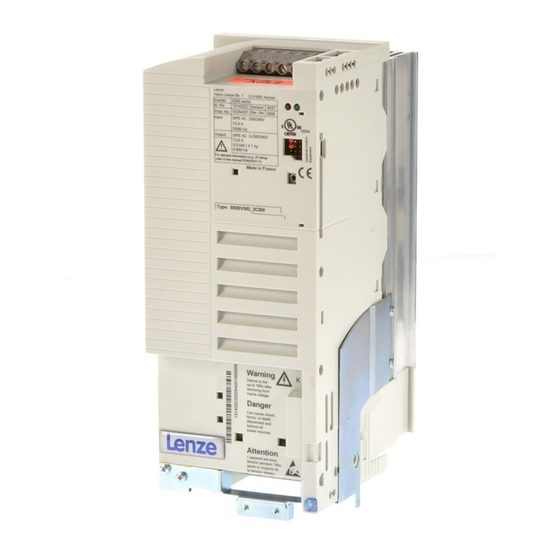
8200 motec frequency inverter
0.25 kw ... 7.5 kw
Hide thumbs
Also See for 8200:
- System manual (588 pages) ,
- Manual (313 pages) ,
- Mounting instructions (239 pages)

Subscribe to Our Youtube Channel
Related Manuals for Lenze 8200


Summary of Contents for Lenze 8200
- Page 1 EDB82MV752 .5eI Operating Instructions Global Drive 8200 motec frequency inverter 0.25 kW ... 7.5 kW...
- Page 2 E 2006 Lenze Drive Systems GmbH No part of this documentation may be copied or made available without the explicit written approval of Lenze Drive Systems GmbH. We have compiled all information in this documentation with great care and have checked them with regard to compliance with the hardware and software described.
-
Page 3: Table Of Contents
............2−1 General safety and application instructions for Lenze controllers ...... - Page 4 Contents 5 Commissioning ............5−1 Before you start .
- Page 5 Contents 7.3.1 Start conditions/flying−restart circuit ......... . . 7−18 7.3.2 Controlled deceleration after mains failure/mains disconnection...
- Page 6 11.2.3 Rated data of Lenze brake resistors ..........
- Page 7 Contents 14.3 Signal processing in the standard I/O function blocks ........14−3 14.3.1 Speed setpoint conditioning (NSET1)
-
Page 8: Preface And General Information
Frequency inverter 8200 motec Drive 8200 motec in combination with a geared motor, a three−phase AC motor and other Lenze drive components AutomationInterF ace: Interface for a communication module. Accessible from the outside at the heatsink of the motec. F unctionInterF ace: Interface for a function module. Is inside the motec. -
Page 9: Legal Regulations
· The specifications, processes, and circuitry described in these instructions are for guidance only and must be adapted to your own specific application. Lenze does not take responsibility for the suitability of the process and circuit proposals. · The specifications in these Instructions describe the product features without guaranteeing them. -
Page 10: Safety Information
General safety and application instructions for Lenze controllers (According to: Low−Voltage Directive 73/23/EEC) General Depending on their degree of protection, some parts of Lenze controllers (frequency inverters, servo inverters, DC controllers) and their accessory components can be live, moving and rotating during operation. Surfaces can be hot. - Page 11 Reduce housing openings and cutouts to a minimum. Lenze controllers can cause a DC current in the protective conductor. If a residual current device (RCD) is used as a protective means in the case of direct or indirect contact, only a residual current device (RCD) of type B may be used on the current supply side of the controller.
-
Page 12: General Safety And Application Instructions For Lenze Motors
Safety instructions Lenze low−voltage machinery General safety and application instructions for Lenze motors (According to: Low−Voltage Directive 73/23/EEC) General Low−voltage machines have hazardous live and rotating parts and possibly also hot surfaces. Synchronous machines induce voltages at open terminals during operation. - Page 13 Safety instructions Lenze low−voltage machinery Electrical connection All operations must only be carried out by qualified and skilled personnel on the low−voltage machine at standstill and deenergised and provided with a safe guard to prevent an unintentional restart.This also applies to auxiliary circuits (e. g. brake, encoder, blower).
-
Page 14: Residual Hazards
– Skin contact with the heatsink causes burns. · Device 8200 motec 3 ... 7.5 kW (E82MV302_4B, E82MV402_4B, E82MV552_4B, E82MV752_4B): protection Frequent mains switching (e.g. inching mode via mains contactor) may overload and destroy the input current limitation of the controller: –... - Page 15 Safety instructions Residual hazards, Layout of the safety instructions 2−6 EDB82MV752 EN 5.2...
-
Page 16: Technical Data
Technical data General data/operating conditions Technical data General data/operating conditions Standards and operating conditions Conformity Low−Voltage Directive (73/23/EEC) EMC Directive (93/68/EEC) Approvals UL 508C Underwriter Laboratories (File−No. E132659) Power Conversion Equipment Vibration resistance Acceleration resistant up to 2g (Germanischer Lloyd, general conditions) Climatic conditions Storage IEC/EN 60721−3−1... - Page 17 Technical data General data/operating conditions General electrical data Complies with requirements according to EN 61800−3/A11 Noise emission Motor mounting Complies with the limit classes A and B (for B: at a max. switching frequency of 8 kHz ) acc. to EN 61800−3 Wall mounting Complies with the limit class A acc.
- Page 18 Technical data General data/operating conditions Open and closed loop control Open and closed−loop control methods V/f characteristic control (linear, quadratic), vector control, torque selection Switching frequency optionally 2 kHz, 4 kHz, 8 kHz, 16 kHz Torque behaviour Maximum torque 1.8 x M for 60 s if rated motor power = rated controller power Setting range...
- Page 19 Technical data General data/operating conditions Inputs and outputs Analog with standard I/O 1 input, optionally bipolar inputs/outputs 1 output with application I/O 2 inputs, optionally bipolar 2 outputs Digital with standard I/O 4 inputs, optionally 1 frequency input, single−track 0 ... 10 kHz / two−track 0...1 kHz; 1 input for controller inhibit inputs/outputs 1 output with application I/O...
-
Page 20: Rated Data At A Mains Voltage Of 230 V
190 x 138 x 100 Weight m [kg] Bold print = data for operation at a switching frequency of 8 kHz (Lenze setting) Currents for periodic load change: 1 min overcurrent time with I and 2 min base load time with 75 % I Under different operating conditions possible for some types: Operation with increased rated output current with the same load change cycle (^ 3−6) -
Page 21: Operation With Increased Rated Power
0.37 0.55 Three−phase asynchronous motor [hp] 0.75 (4−pole) 8200 motec Type E82MV251_2B E82MV371_2B Mains voltage 1/N/PE AC 180 V − 0 % ... 264 V + 0 % ; 45 Hz − 0 % ... 65 Hz + 0 %... -
Page 22: Rated Data At A Mains Voltage Of 400/500 V
325 x 211 x 163 (223**) Weight m [kg] Bold print = data for operation at a switching frequency of 8 kHz (Lenze setting) Currents for periodic load change: 1 min overcurrent time with I and 2 min base load time with 75 % I Under different operating conditions possible for some types: Operation with increases rated output current with the same load change cycle (^ 3−9) - Page 23 Observe national and regional regulations Current derating Depending on the operating conditions and the use of the 8200 motec, the types E82MV302_4B to EMV752_4B may require a reduction of the rated output current in continuous operation: 8200 motec mounted on...
-
Page 24: Operation With Increased Rated Power
Weight m [kg] Bold print = data for operation at a switching frequency of 8 kHz (Lenze setting) Currents for periodic load change with 1 min overcurrent time with I and 2 min base load time with 75 % I for wall mounting or with a supplementary module (E82ZMV) 3−9... - Page 25 Observe national and regional regulations Current derating Depending on the operating conditions and the use of the 8200 motec, the types E82MV302_4B to EMV552_4B may require a reduction of the rated output current in continuous operation: 8200 motec mounted on...
-
Page 26: Installation
Mechanical installation 4.1.1 Important notes · The 8200 motec frequency inverter can be used in all operating positions. · Free space: – Allow a free space of 100 mm above and below the inverter. – Ensure unimpeded ventilation of cooling air and outlet of exhaust air. -
Page 27: Dimensions
Installation Mechanical installation − Dimensions 4.1.3 Dimensions 8200mot001 Fig. 4−1 Dimensions 0.25 ... 2.2 kW [mm] [mm] [mm] [mm] [mm] [mm] E82MV251_2B E82MV371_2B E82EV551_4B E82EV751_4B E82EV152_4B E82EV222_4B 82mot443 Fig. 4−2 Dimensions 3 ... 7.5 kW Type a [mm] b [mm] c [mm] d [mm] [mm]... -
Page 28: Electrical Installation
– By overcurrent relay or temperature monitoring. – We recommend to use PTC thermistors or thermal contacts for motor temperature monitoring. (Lenze three−phase AC motors are equipped with thermal contacts (NC contacts) as standard) – PTC thermistors or thermal contacts can be connected to the controller. -
Page 29: Mains Types/Mains Conditions
If you observe all measures given, the controllers comply with the limit values according to EN 61000−3−2. The machine/system manufacturer is responsible for the compliance with the requirements for the machine/system: Supply voltage Power Measure 8200 motec [kW] E82MV251_2B 0.25 1/N/PE AC 230 V Use ELN1−0900H005 mains choke E82MV371_2B 0.37... -
Page 30: Operation With Earth−Leakage Circuit Breaker
Installation Electrical installation − Important notes 4.2.1.5 Operation with earth−leakage circuit breaker Danger! The controllers have an internal mains rectifier. In the event of a short circuit to frame, a DC residual current can prevent the activation of the AC−sensitive or pulse−current sensitive earth−leakage circuit breakers and thus block the protective function for all electrical equipment operated on this earth−leakage circuit breaker. -
Page 31: Specification Of The Cables Used
Installation Electrical installation − Important notes 4.2.1.7 Specification of the cables used Power terminals · The cables used must comply with the approvals required for the application (e.g. UL). · Use low−capacitance motor cables. Capacitance per unit length: – Core/core £ 75 pF/m –... -
Page 32: Installation According To Emc
Installation Electrical installation − Installation according to EMC requirements 4.2.2 Installation according to EMC The electromagnetic compatibility (EMC) of a machine depends on the type of installation and the care taken. If you observe the following measures, you can assume that the machine will operate without any EMC problems caused by the drive system. -
Page 33: Power Connections
Installation Electrical installation − Connections 4.2.3 Power connections See corresponding Mounting Instructions 4.2.4 Control connections The basic controller version is not provided with control terminals. Different I/O function modules are available for the FIF interface to equip the controllers with control terminals. 4.2.4.1 Mounting/dismounting the I/O function module See corresponding Mounting Instructions... -
Page 34: Terminal Assignment − Standard I/O E82Zafsc001
Installation Electrical installation − Connections 4.2.4.2 Terminal assignment − standard I/O E82ZAFSC001 Stop ! Control cables must always be shielded to prevent interference injections! Electrical connection Terminal strip with screw connection Possible connections rigid: 1.5 mm (AWG 16) flexible: without wire end ferrule 1.0 mm (AWG 18) with wire end ferrule, without plastic sleeve... - Page 35 0 ... 5 V. Otherwise it is not possible to use the whole speed range. −3− Switch position Signal at X3/8 C0034 0 ... 5 V 0 ... 10 V (Lenze setting) 0 ... 20 mA 4 ... 20 mA 4 ... 20 mA Open−circuit monitoring −10 V ... +10 V 4−10...
- Page 36 Adjust offset (C0026) and gain (C0027) separately for each function module: After replacing the function module or the basic device After loading the Lenze setting Alternatively frequency input 0 ... 10 kHz single−tracked or 0 ...1 kHz double−tracked, configuration via C0425 4−11...
-
Page 37: Terminal Assignment − Application I/O E82Zafac001
Installation Electrical installation − Connections 4.2.4.3 Terminal assignment − application I/O E82ZAFAC001 Stop ! Control cables must always be shielded to prevent interference injections! Electrical connection Terminal strip with screw connection Possible connections rigid: 1.5 mm (AWG 16) flexible: without wire end ferrule 1.0 mm (AWG 18) with wire end ferrule, without plastic sleeve... - Page 38 Installation Electrical installation − Connections Controller inhibit (CINH) supply via internal voltage source (X3.3/20) 1U 9 +5 V 1I 2U 62 63 X3.2 X3.1 1k … 10k AIN1 AIN2 AOUT1 AOUT2 +20 V 7 A4 20 28 E1 E2 E3 E4 E5 E6 X3.3 DIGOUT1 DIGOUT2 DFOUT1...
- Page 39 Installation Electrical installation − Connections Jumper setting for inputs Lenze setting (see bold print in tables) Ÿ 1 − 3 Ÿ 2 − 4 Ÿ 7 − 9 Ÿ 8 − 10 Note! If a setpoint potentiometer is internally supplied via X3.2/9, the jumper must be set to a voltage range between 0 ...
- Page 40 Installation Electrical installation − Connections Jumper setting for outputs Lenze setting (see bold print in tables) Ÿ 1 − 3 Ÿ 2 − 4 Ÿ 7 − 9 Ÿ 8 − 10 X3.1/62 Possible levels 0 ... 10 V 0 ... 20 mA 4 ...
-
Page 41: Wiring Of Bus Function Modules
Installation Electrical installation − Connections X3.3/ −6− Signal type Function Level (Lenze setting, in bold print) Digital outputs Ready for operation 0/+20 V at DC internal not prefabricated 0/+24 V at DC external − GND, reference potential − Frequency DC bus voltage... -
Page 42: Commissioning
Possible consequences: The DC−bus capacitors and thus the controller will be damaged at the first switch−on. Protective measures: Anodize the DC−bus capacitors before commissioning. A detailed set of instructions can be downloaded from the Internet (www.Lenze.com). 5−1 EDB82MV752 EN 5.2... -
Page 43: Menu Structure
· The user menu – is active after every mains switching or keypad attachment during operation. – contains all codes for a standard application with linear V/f characteristic control (Lenze setting). – can be modified as required under C0517. ·... -
Page 44: Changing And Saving Parameters
Keys Result Action Connect keypad Function is activated. The first code in the user menu will be displayed (C0517/1, Lenze setting: C0050 = output frequency). xx.xx If necessary change to Change to function bar 2 the menu "ALL" Select menu "ALL" (list of all codes) Œ... -
Page 45: Selection Of The Correct Control Mode
Commissioning Selection of the correct control mode Selection of the correct control mode The following table helps you to find the correct control mode for standard applications. You can choose between V/f characteristic control, vector control and sensor torque control: V/f characteristic control is the classic control mode for standard applications. - Page 46 Commissioning Selection of the correct control mode Application Operating mode C0014 recommended alternatively Stand−alone drives with extremely alternating loads −4− −2− with heavy start conditions −4− −2− with speed control (speed feedback) −2− −4− with high dynamic response (e. g. positioning and infeed drives) −2−...
-
Page 47: Commissioning − V/F Characteristic Control
Commissioning V/f characteristic control Commissioning − V/f characteristic control 5.4.1 Commissioning without function module Stop ! · The controller can only be used when the FIF cover is mounted! – If the FIF cover is missing, the green LED is blinking (keypad: dc). The controller is inhibited. - Page 48 Go to the menu A Check the fan monitoring setting under code C0608: – for 8200 motec 0.25...0.37 kW and 0.55...2.2 kW: C0608 = 0! (default setting) – for 8200 motec 3...7.5 kW: C0608 =1 (recommended) or C0608 = 2!
-
Page 49: Commissioning With Standard I/O Function Module
(C0034) same range (see Mounting Instructions for the standard I/O) Lenze setting: −0−, (0 ... 5 V/0 ... 10 V/0 ... 20 mA) Adapt the terminal configuration to the wiring (C0007) Œ j g f k i h PS 0007 ‚... - Page 50 Go to the menu A Check the fan monitoring setting under code C0608: – for 8200 motec 0.25...0.37 kW and 0.55...2.2 kW: C0608 = 0! (default setting) – for 8200 motec 3...7.5 kW: C0608 =1 (recommended) or C0608 = 2!
-
Page 51: Commissioning − Vector Control
PS 0050 ‚ m n o your drive Set the minimum output frequency (C0010) C0011 Lenze setting: 0.00 Hz Set the maximum output frequency (C0011) Lenze setting: 50.00 Hz C0010 100 % Set the acceleration time T (C0012) - Page 52 Go to the menu A Check the fan monitoring setting under code C0608: – for 8200 motec 0.25...0.37 kW and 0.55...2.2 kW: C0608 = 0! (default setting) – for 8200 motec 3...7.5 kW: C0608 =1 (recommended) or C0608 = 2!
-
Page 53: Commissioning With Standard I/O Function Module
(C0034) same range (see Mounting Instructions for the standard I/O) Lenze setting: −0−, (0 ... 5 V/0 ... 10 V/0 ... 20 mA) Enter the motor data See motor nameplate Rated motor speed (C0087) Lenze setting: 1390 rpm... - Page 54 Go to the menu A Check the fan monitoring setting under code C0608: – for 8200 motec 0.25...0.37 kW and 0.55...2.2 kW: C0608 = 0! (default setting) – for 8200 motec 3...7.5 kW: C0608 =1 (recommended) or C0608 = 2!
-
Page 55: Vector Control Optimisation
Commissioning Vector control 5.5.3 Vector control optimisation In general, the vector control is ready for operation without any further measures after the motor parameters have been identified. The vector control must only be optimised in case of the following drive behaviour:7 Drive behaviour Remedy... -
Page 56: General Information
Detailed information on other bus modules can be found in the Operating Instructions of the modules. Tip! · The signal flow diagrams provide an overview of all configurable signals. (^ 14−1) · If you make a mistake during parameter setting, load the Lenze setting with C0002 and start again. 6−1 EDB82MV752 EN 5.2... -
Page 57: Parameter Setting Via Keypad
‚ m n o 88888 °C When the mains voltage is switched on, the communication module is ready for operation. You can communicate with the drive. 8200 motec 8200mot031 6.2.2 Displays and functions Function keys Status displays j g f k i h PS... - Page 58 Warning active Error active Bar graph display Set value in C0004 in %. Display range: − 180 % ... + 180 % (every scale line = 20 %) (Lenze setting: device utilisation C0056). Function bar 1 Function Meaning Explanation Setpoint selection via Not possible with active password protection (display = "loc"...
-
Page 59: Menu Structure
The User · menu – is active after every mains switching or keypad attachment during operation. – contains all codes for a standard application with linear V/f characteristic control (Lenze setting). – can be compiled as required in C0517. ·... -
Page 60: Changing And Saving Parameters Using The Keypad
Action Result Comment Example sequence Attach keypad Function is active. The first code in the user menu (C0517/1, Lenze setting: C0050 = output frequency) is displayed. xx.xx If required, Change to function bar 2 change to the menu "ALL"... -
Page 61: Remote Parameterisation Of System Bus Nodes
0517 0517 The existing setting will be Select Code saved in C0517/1 is displayed overwritten. memory (Lenze setting: output frequency C0050) location Select subcode 001 ... 010 Change entry Enter code number XXXXX It is not checked whether the code number exists! Enter "0"... -
Page 62: Activation Of Password Protection
Parameter setting With keypad 6.2.8 Activation of password protection Tip! · If the password protection is activated (C0094 = 1 ... 9999) only the user menu can be freely accessed. · All other functions require the correct password. · Pleas observe that also the password−protected parameters are overwritten when the parameter sets are transferred. - Page 63 Parameter setting With keypad 6.2.8.3 Deactivating password protection permanently Action Result Comment Example sequence t pass Change the Deactivating password 123 is blinking "ALL" menu permanently Set password pass XXXX v STOre Confirm password goes off Change to function bar 2 Select menu "ALL"...
-
Page 64: Parameter Setting Using The Lecom−A (Rs232) Communication Module
Parameter setting With communication module LECOM−A (RS232) Parameter setting using the LECOM−A (RS232) communication module The LECOM−A (RS232) communication module connects the controller to a host (e.g. PC) via the RS232 interface. You need the following accessory components to use the communication module: ·... -
Page 65: Communication Times
Parameter setting With communication module LECOM−A (RS232) 6.3.1.2 Communication times The time required for communication with the drive can be displayed as a sequence of time segments. The communication times depend on the baud rate set in C0125: Section Active component Action Application program in the host system Starts request on the controller... -
Page 66: Wiring To A Host (Pc Or Plc)
Tip! · The controller has a double basic insulation to EN 50178. An additional electrical isolation is not required. · Use the Lenze accessories listed for wiring. 6.3.2.1 Notes on self−made PC system cables Specification for RS232 Cable type LIYCY 4 x 0.25 mm... -
Page 67: Parameter Setting Using Lecom−A (Rs232)
LECOM format Interpretation of response message: VH = hexadecimal; VD = decimal; VS = ASCII string; VO = octet Parameter Settings/options Contents or meaning of the parameter values (bold print = Lenze setting) Important Important additional information 6−12 EDB82MV752 EN 5.2... - Page 68 Parameter setting With communication module LECOM−A (RS232) Code Parameter Important Designation LECOM Settings/options format C0068 Operating status Assignment 3|2|1|0 TRIP error number Submission of the 10th digit of the LECOM error number. Example: TRIP OH (LECOM no. 50) = 0110 (5) 7|6|5|4 Last communication error 0000 No error...
- Page 69 Parameter setting With communication module LECOM−A (RS232) Code Parameter Important Designation LECOM Settings/options format · C0249 LECOM code For compatibility with LECOM−A/B drivers V1.0 (maximum possible Code bank Addressable codes bank code number 255). 0000 ... 0255 · With the code bank, an offset of 250 is added to the code number. 1 0250 ...
- Page 70 Parameter setting With communication module LECOM−A (RS232) Code Parameter Important Designation LECOM Settings/options format C1962 Extended error 0 No error Internal error 1 Invalid service identification 2 Invalid call identification User error in the host 3 Invalid data type 4 Invalid subcode number 5 Invalid code number 6 Invalid parameter −...
-
Page 71: Troubleshooting And Fault Elimination Lecom−A (Rs232)
Parameter setting With communication module LECOM−A (RS232) 6.3.5 Troubleshooting and fault elimination LECOM−A (RS232) Three LEDs on the LECOM−A (RS232) communication module show the status: Green LED (Vcc) Yellow LED (RxD) Yellow LED (TxD) Blinking Communication module is not initialised Telegram is received. -
Page 72: Function Library
– It is thus possible that double assignments occur when targets are assigned to sources. – For instance, the assignment of E1 remains the same even if the frequency input E1 is activated (Lenze setting: "JOG1 activation!). The previous assignment must be deleted with C0410/1 = 255 to ensure trouble−free operation. -
Page 73: Operating Mode
Function library Selection of control mode, optimisation of operating behaviour Operating mode Description The control mode of the controller can be selected via the operating mode. You can select between · V/f characteristic control · Vector control · Sensorless torque control Selection of the correct operating mode V/f characteristic control is the classic operating mode for standard applications. - Page 74 Function library Selection of control mode, optimisation of operating behaviour Application Operating mode Setting in C0014 recommended alternatively Single drives With extremely alternating loads With high starting duty With speed control (speed feedback) With high dynamic response (e. g. positioning and infeed drives) −...
-
Page 75: V/F Characteristic Control
8200vec540 8200vec539 Fig. 7−2 Linear and square−law V/f characteristic Codes for parameter setting Code Possible settings IMPORTANT Name Lenze Selection · ^ 7−2 C0014 Operating mode Commissioning is possible without V/f characteristic control V ~ f identifying motor parameters (linear characteristic with constant V boost) ·... - Page 76 Function library Selection of control mode, optimisation of operating behaviour Setting the V/f characteristic Under C0014 select the V/f characteristic suitable for your application. Note! The following must be observed when operating drives with square−law V/f characteristic: High moments of inertia reduce the acceleration of the drive. This drive behaviour can be avoided by using the linear V/f characteristic via the parameter set changeover during the acceleration.
- Page 77 Function library Selection of control mode, optimisation of operating behaviour Typical values for C0015 400 V E82xVxxxK4 controller 230 V E82xVxxxK2 controller motor C0015 motor C0015 Voltage Frequency Connection Voltage Frequency Connection 230/400 V 50 Hz 50 Hz 230/400 V 50 Hz 50 Hz 220/380 V...
- Page 78 Function library Selection of control mode, optimisation of operating behaviour Setting of V boost Load−independent boost of the motor voltage for output frequencies below the V/f rated frequency. This serves to optimise the torque behaviour. C0016 must always be adapted to the asynchronous motor used. Otherwise, the motor might be destroyed by overtemperature or the controller might be driven with overcurrent: 1.
-
Page 79: Vector Control
Compared with the V/f characteristic control the vector control offers considerably higher torque and lower current consumption during idle running. The vector control is an improved motor current control following the Lenze FTC technology. Select vector control for operation of the following drives: ·... - Page 80 Motor stator 0.000 {0.1 mH} 200.0 inductance 0.00 0.00 {0.01 mH} 200.00 Only 8200 vector 15 ... 90 kW ^ 7−48 C0148* Motor parameter Only when the motor is cold! Ready identification 1. Inhibit controller, wait until drive is at standstill 2.
-
Page 81: Sensorless Torque Control With Speed Limitation
16.00 = P component not active ^ 7−56 à C0078* Integral action time {1 ms} 9990 Only 8200 vector 15 ... 90 kW controller à = I component not active Rated motor speed à ^ 7−48 à C0087 {1 rpm}... - Page 82 Motor stator 0.000 {0.1 mH} 200.0 inductance 0.00 0.00 {0.01 mH} 200.00 Only 8200 vector 15 ... 90 kW ^ 7−48 C0148* Motor parameter Only when the motor is cold! Ready identification 1. Inhibit controller, wait until drive is at standstill 2.
- Page 83 Function library Selection of control mode, optimisation of operating behaviour Optimising the sensorless torque control In general, the sensorless torque control is ready for operation after the motor parameters have been identified. The drive performance can be optimised by manually setting several parameters: Drive performance Remedy Torque is not constant...
-
Page 84: Optimising The Operating Behaviour
The slip can be partly compensated by setting C0021 accordingly. The slip compensation is effective for all control modes (C0014). Codes for parameter setting Code Possible settings IMPORTANT Name Lenze Selection ^ 7−13 C0021 Slip compensation −50.0 {0.1 %} 50.0 C0021 is calculated and stored under... -
Page 85: Inverter Switching Frequency
The switching frequency of the inverter influences the smooth running performance, the power loss inside the controller, and the noise generation in the connected motor. The Lenze setting of 8 kHz is the optimum value for standard applications. The following general rule applies: The lower the switching frequency the ·... - Page 86 Switching General rule: 2 kHz sin frequency The lower the switching frequency the 4 kHz sin · (only 8200 vector lower the power loss 8 kHz sin · 15 ... 90 kW) higher the noise generation low noise generation 16 kHz sin Only operate mid−frequency motors at 8...
-
Page 87: Oscillation Damping
20 ... 40 Hz. As a result, operation can be instable (current and speed fluctuations). Codes for parameter setting Code Possible settings IMPORTANT Name Lenze Selection ^ 7−16 C0079 Oscillation damping Adjustment 1. Approach with speed oscillations. -
Page 88: Skip Frequencies
The bandwidth (nf) determines the skip frequency range. The function is in the block NSET1 before the ramp function generator. Codes for parameter setting Code Possible settings IMPORTANT Name Lenze Selection ^ 7−17 C0625* Skip frequency 1 0.00 0.00 {0.02 Hz} 650.00... -
Page 89: Behaviour In The Event Of Mains Switching, Mains Failure Or Controller Inhibit
With activated flying−restart circuit the controller automatically synchronises to a coasting motor after mains disconnection or adds a setpoint signal. Codes for parameter setting Code Possible settings IMPORTANT Name Lenze Selection ^ 7−18 C0142 Start condition Automatic restart after mains connection Start after HIGH−LOW−HIGH changes at... -
Page 90: Controlled Deceleration After Mains Failure/Mains Disconnection
Bridge X3/28 with HIGH level and start the controller with the function QSP" (C0142 = 3 and C0106 = 0 s). · The flying−restart circuit is now only activated for for the first mains connection. 7.3.2 Controlled deceleration after mains failure/mains disconnection Note! This function cannot be used with a 8200 motec! 7−19 EDB82MV752 EN 5.2... -
Page 91: Controller Inhibit
The drive could restart any time. Codes for parameter setting Code Possible settings IMPORTANT Name Lenze Selection ^ 7−20 C0040* Controller inhibit Controller can only be enabled if X3/28 = −0− Controller inhibited (CINH) -
Page 92: Limit Value Setting
C0011 Maximum output 50.00 7.50 {0.02 Hz} 650.00 à Speed setting range 1 : 6 for Lenze à frequency 87 Hz uSEr geared motors: Setting absolutely required for operation with Lenze geared motors. ·... - Page 93 Function library Limit value setting Adjustment Relation between output frequency and synchronous speed of the motor: −1 + C0011 @ 60 Synchronous motor speed [min rsyn rsyn C0011 Max. output frequency [Hz] No. of pole pairs (1, 2, 3, ...) + 50 @ 60 Example: + 1500 min...
-
Page 94: Current Limits
Name Lenze Selection ^ 7−23 C0022 limit (motor {1 %} 150 Only 8200 vector 15 ... 90 kW: mode) If C0022 = 150 %, 180 % I are available for max. 3 s. after controller enable ^ 7−23 C0023 −limit in the... -
Page 95: Acceleration, Deceleration, Braking, Stopping
When operating with application I/O three additional deceleration times and acceleration times can be activated via digital signals. Codes for parameter setting Code Possible settings IMPORTANT Name Lenze Selection ^ 7−24 C0012 Acceleration time 5.00 0.00 {0.02 s} 1300.00 Reference: frequency change 0 Hz ... - Page 96 Function library Acceleration, deceleration, braking, stopping Note! If the acceleration and deceleration times are set too short the controller may switch off with TRIP OC5 under unfavorable service conditions. In these cases, the acceleration and deceleration times should be set short enough so that the drive can follow the speed profile without reaching I of the controller.
- Page 97 Function library Acceleration, deceleration, braking, stopping Special functions for the ramp function generator Setting the ramp function generator to 0 The ramp function generator input of the main setpoint can be set to 0 under C0410/6: · The main setpoint decelerates to 0 Hz along the deceleration ramp (C0013) as long as the function is active.
-
Page 98: Quick Stop
C0105. Reduce the time setting under C0105 to reach the desired deceleration time for quick stop. Codes for parameter setting Code Possible settings IMPORTANT Name Lenze Selection · ^ 7−27 C0105 Deceleration time 5.00 0.00 {0.02 s}... -
Page 99: Change Of Direction Of Rotation
Function library Acceleration, deceleration, braking, stopping Note! Quick stop can also be activated when using the function "fail−safe change of the direction of rotation". (^ 7−28) In addition to the free configuration under C0410 you can also use the fixed assignment under C0007 to combine the function with a digital input. - Page 100 Function library Acceleration, deceleration, braking, stopping Fail−safe change of the direction of rotation Link C0410/22 and C0410/23 with one digital signal source each. If the direction of rotation is changed, the drive brakes along the quick stop ramp (C0105) and accelerates along the acceleration ramp (C0012) in the other direction or rotation.
-
Page 101: Dc Braking (Dcb)
· Automatic DC braking improves the starting performance of the motor e.g. when operating hoists. Codes for parameter setting Code Possible settings IMPORTANT Name Lenze Selection 650.00 Hold time ð C0106 ^ 7−30 C0019 Operating threshold 0.10 0.00 {0.02 Hz} −... -
Page 102: Ac Motor Braking
Use C0019 to set a dead band in the setpoint. If DC−injection braking is not to be active here, set C0106 = 0.00 s. · C0019 can be referred to a process variable. 7.5.5 AC motor braking Note! This function cannot be used with a 8200 motec! 7−31 EDB82MV752 EN 5.2... -
Page 103: Configuration Of Analog And Digital Setpoints And Actual Values
(AIF−IN.W1 or AIF−IN.W2). Link the AIF input word with the internal analog signal under C0412. Codes for parameter setting Code Possible settings IMPORTANT Name Lenze Selection · ^ 7−32 C0001 Selection of Changing C0001 will cause the changes... - Page 104 Function library Configuration of analog and digital setpoints and actual values Note! With C0001 = 0, 1 or 2 the operation can start after the controller has been released. C0001 = 3 must be set to select a setpoint via a process data channel of an AIF bus module! Otherwise the process data will not be evaluated.
-
Page 105: Analog Setpoints Via Terminal
Analog setpoints via terminal Description Selection and adjustment of analog signals via terminal as setpoint or actual value. Codes for parameter setting Code Possible settings IMPORTANT Name Lenze Selection ^ 7−34 C0034* Setpoint selection Observe the switch position of the function range module! Standard–I/O (X3/8) - Page 106 Function library Configuration of analog and digital setpoints and actual values Code Possible settings IMPORTANT Name Lenze Selection ^ 7−34 C0430* Automatic analog not active Gain and offset are calculated by two points input adjustment from the setpoint characteristic. Choose...
- Page 107 Function library Configuration of analog and digital setpoints and actual values Note! C0026, C0027, C0413 and C0414 are identical in all parameter sets. For operation with application I/O the setpoint inputs can be adjusted automatically via C0430, C0431 and C0432: –...
- Page 108 Function library Configuration of analog and digital setpoints and actual values Inverse setpoint selection Deadband C0011 Setpoint 0 mA signal 0 kHz 10 V 20 mA 10 kHz 8200vec531 Fig. 7−10 Gain and offset at inverse setpoint selection Example of inverse setpoint selection A dead band of +2 V (= 20 %) is to be set for an inverse setpoint selection (0 ...
- Page 109 Function library Configuration of analog and digital setpoints and actual values Example: Calibration when using a process controller Example for pressure control If, for instance, the control range of a pressure control is to be limited to a value lower than the rated sensor value P , the effective pressure setpoint can be proportionally reduced through the gain of the analog input (C0027, C0414):...
-
Page 110: Digital Setpoints Via Frequency Input
For operation with application I/O – single−tracked: 0 ... 100 kHz at X3/E1 – two−tracked: 0 ...100 kHz at X3/E1 and X3/E2 Codes for parameter setting Code Possible settings IMPORTANT Name Lenze Selection · ^ 7−39 C0425* Configuration = Normalisation frequency frequency input –... - Page 111 Function library Configuration of analog and digital setpoints and actual values Code Possible settings IMPORTANT Name Lenze Selection C0428* Gain frequency {0.1 %} 1500.0 output (DFOUT1−OUT) · C0435* Automatic 4096 Only require for speed control with frequency input digital feedback via HTL encoder = not active ·...
-
Page 112: Setpoints Via Function "Motor Potentiometer"
The output frequency in changed via the acceleration and deceleration times set for the main setpoint (C0012/C0013) or for the additional setpoint (C0220/C0221). Codes for parameter setting Code Possible settings IMPORTANT Name Lenze Selection · ^ 7−41 C0265 Configuration motor Start value: output frequency which is... - Page 113 Function library Configuration of analog and digital setpoints and actual values Example: Triggering the "motor potentiometer" function via NC contacts. Configuration E1 = "UP": C0410/7 = 1 E2 = "DOWN": C0410/8 = 2 Fig. 7−12 Motor potentiometer with NC contacts Important Note! Proceed as follows if the setpoint selection via motor potentiometer is used...
-
Page 114: Setpoints Via Fixed Setpoints (Jog)
You can store up to three fixed setpoints per parameter set and retrieve them using digital input signals. At operation with application I/O 7 fixed setpoints are available per parameter set. Codes for parameter setting Code Possible settings IMPORTANT Name Lenze Selection ^ 7−43 650.00 JOG = fixed setpoint C0037 JOG1 20.00 −650.00 {0.02 Hz}... - Page 115 Function library Configuration of analog and digital setpoints and actual values Operation with application I/O · The signal NSET1−JOG1/3/5 must be combined with a digital input signal under C0410/1. · The signal NSET1−JOG2/3/6/7 must be combined with a digital input signal under C0410/2. ·...
-
Page 116: Setpoints Via Keypad
The drive can start again after controller enable! Codes for parameter setting Code Possible settings IMPORTANT Name Lenze Selection ^ 7−45 C0044* Setpoint 2 −650.00 {0.02 Hz} 650.00 The value set will be lost when (NSET1−N2) -
Page 117: Setpoints Via A Bus System
Function library Configuration of analog and digital setpoints and actual values Setting tips · The setpoint via keypad has an effect on setpoint 1 (NSET1−N1) and setpoint 2 (NSET1−N2). If you want to select different setpoints via keypad: – Separate the linkage of NSET1−N1 and NSET1−N2 with analog input signals (C0412/1 = 0 and C0412/2 = 0). -
Page 118: Setpoint Changeover (Hand/Remote Changeover)
Activation of "bus operation keypad or PC" 1. Internally invert a digital input (X3/E5 or X3/E6) not used in the Lenze setting under C0411. 2. Assign this input C0410/17 (DCTRL1−H/Re) to activate manual operation. 3. If the inversion of the digital input reset (C0411 = 0), remote operation will be active again. -
Page 119: Automatic Detection Of Motor Data
Selection ^ 7−48 {0.001 W} C0084 Motor stator 0.000 0.000 64.000 resistance {0.1 m W} 6500.0 Only 8200 vector 15 ... 90 kW à ^ 7−48 à C0087 Rated motor speed {1 rpm} 16000 Depending on the controller à ^ 7−48 à... - Page 120 Function library Motor data entry/automatic detection Activation Note! Ensure that the motor is cold when the identification is started! During identification current flow via the controller outputs U, V. The load machine can remain connected. Holding brakes can remain in their braking position.
-
Page 121: Process Controller
(potentiometer, PLC), the controller must be equipped with an application I/O to build up a control circuit. Codes for parameter setting Code Possible settings IMPORTANT Name Lenze Selection ^ 7−50 C0070 Process controller 1.00 0.00 {0.01}... - Page 122 Function library Process controller, current limitation controller Pressure control and flow control · The differential component K (C0072) is generally not required for pressure and flow control. · Set the influence (C0074) to 100 %. · Deactivate the frequency feedforward control (C0238 = 0). Code Setting for Gases...
- Page 123 Function 1. The dancer deflects to the bottom. The dancer control (V ) decreases. 2. V2 increases. +10 V 8200 0 V ... 10 V ~ V1 8200vec534 Fig. 7−13 Example: Dancer control with adding influence of the process controller Example of subtractive influence The effective direction of the process controller output to the main setpoint is subtractive.
-
Page 124: Setpoint Selection For The Process Controller
· the pressure setpoint for a pressure control. Codes for parameter setting Code Possible settings IMPORTANT Name Lenze Selection ^ 7−53 C0138* Process controller 0.00 −650.00 {0.02 Hz} 650.00 The value set will be lost when... -
Page 125: Actual Value Selection For The Process Controller
Description The actual value is the process feedback signal (e.g. from a pressure encoder or a speed encoder). Codes for parameter setting Code Possible settings IMPORTANT Name Lenze Selection ^ 7−54 C0051* Output frequency −650.00 {0.02 Hz} 650.00 The value set will be lost when... -
Page 126: Switching Off Process Controller Functions
K can be connected. · Application: e.g. dancer position control Codes for parameter setting Code Possible settings IMPORTANT Name Lenze Selection · ^ 7−53 C0184* Frequency {0.1 Hz} 25.0 If the output frequency < C0184, the... -
Page 127: Current−Limit Controller
^ 7−56 à C0078* Integral action time {1 ms} 9990 Only 8200 vector 15 ... 90 kW controller à = I component not active Adjustment The current limiting controller is factory−set so that the drive is stable. Setting notes for power control... -
Page 128: Free Interconnection Of Analog Signals
AIF bus module Only for special applications. Modifications 8 MCTRL1−VOLT−ADD Not assigned (FIXED−FREE) or selected via keypad only when agreed on by Lenze! or parameter channel of an AIF bus module 9 MCTRL1−PHI−ADD Not assigned (FIXED−FREE) or selected via keypad or parameter channel of an AIF bus module 7−57... - Page 129 Function library Free connection of analog signals Code Possible settings IMPORTANT Name Lenze Selection ^ 7−57 C0412 (cont.) Analog signal source possible for C0412 Not assigned (FIXED−FREE) or selected via keypad or parameter channel of an AIF bus module Analog input 1 (AIN1−OUT) X3/8 (Standard−I/O)
-
Page 130: Free Configuration Of Analog Outputs
Use C0111 to permanently assign the analog output X3/62 to some internal signal sources. C0419/1 is automatically adapted. Codes for parameter setting Code Possible settings IMPORTANT Name Lenze Selection ^ 7−59 C0419 Free configuration Output of analog signals to terminal of analog outputs 1 X3/62 (AOUT1−IN) - Page 131 Function library Free connection of analog signals Code Possible settings IMPORTANT Name Lenze Selection ^ 7−59 C0419 Selection 9 ... 25 correspond to the digital functions of the relay output K1 or the digital switching output K1 (C0008) or the (cont.)
- Page 132 Function library Free connection of analog signals Code Possible settings IMPORTANT Name Lenze Selection ^ 7−59 C0419 Possible analog signals for C0419 Output frequency normalised without slip (cont.) (MCTRL1−NOUT−NORM) 6 V/12 mA/5.85 kHz º C0011 Output frequency without slip (MCTRL1−NOUT) Actual process controller value (PCTRL1−ACT)
- Page 133 Function library Free connection of analog signals Code Possible settings IMPORTANT Name Lenze Selection ^ 7−59 C0422* Offset of analog −10.00 {0.01 V} 10.00 outputs Application I/O 0.00 1 X3/62 C0422/1 and C0109 are the same (AOUT1−OFFSET) 2 X3/63 (AOUT2−OFFSET) ^ 7−59...
- Page 134 Function library Free connection of analog signals Output signal at selection 8 When using no process controller the output signal at selection 8 is proportional to the output frequency without slip compensation. Application example for selection 6 The output signal is reciprocal to the output frequency. This signal can be used for the time indication (e.g.
-
Page 135: Free Configuration Of Analog Process Data Output Words
· 3 CAN−OUT1.W1 / Not assigned (FIXED−FREE) CAN−OUT1.W1 and FIF−OUT.W1 are FIF−OUT.W1 digitally defined in the Lenze setting and assigned to the 16 bits of the controller status word 1 (C0417) · Before assigning an analog signal source (C0421/3 ¹ 255), first delete... - Page 136 Function library Free connection of analog signals Code Possible settings IMPORTANT Name Lenze Selection ^ 7−64 C0421* Selection 9 ... 25 correspond to the digital functions of the relay output K1 or the digital switching output K1 (C0008) or the (cont.)
- Page 137 Function library Free connection of analog signals Code Possible settings IMPORTANT Name Lenze Selection ^ 7−64 C0421* Possible analog signals for C0421 ºC0011 Output frequency normalised without slip (cont.) (MCTRL1−NOUT−NORM) 24000 º 480 Hz Output frequency without slip (MCTRL1−NOUT) Actual process controller value (PCTRL1−ACT) Process controller setpoint (PCTRL1−SET1)
- Page 138 Function library Free connection of analog signals Note! The process data output words CAN−OUT1.W1/FIF−OUT.W1, CAN−OUT2.W1 and FIF−OUT.W2 can also be assigned to C0417 and C0418 with 16 bit status information each: – With digital configuration under C0417 or C0418 no simultaneous analog assignment with C0421 (C0421/x = 255)! –...
-
Page 139: Free Interconnection Of Digital Signals
Function library Free connection of digital signals, message output 7.11 Free interconnection of digital signals 7.11.1 Free configuration of digital input signals Description · Internal digital signals can be freely assigned to external digital signal sources. It is thus possible to achieve a freely configured control of the controller –... - Page 140 Function library Free connection of digital signals, message output Codes for parameter setting Code Possible settings IMPORTANT Name Lenze Selection ^ 7−68 C0410 Free configuration Link between digital signal sources and internal digital A selection made under C0007 is copied...
- Page 141 Function library Free connection of digital signals, message output Code Possible settings IMPORTANT Name Lenze Selection ^ 7−68 C0410 (cont.) PCTRL1−FOLL1−0 Not assigned (FIXED−FREE) Compensator at reset ramp C0193 to "0" Reserved Not assigned (FIXED−FREE) NSET1−TI1/3 Not assigned (FIXED−FREE) Activate acceleration times NSET1−TI2/3...
- Page 142 Function library Free connection of digital signals, message output Code Possible settings IMPORTANT Name Lenze Selection ^ 7−68 C0410 Digital signal sources for C0410 Not assigned (FIXED−FREE) (cont.) Digital input X3/E1 (DIGIN1) Digital input X3/E2 (DIGIN2) Digital input X3/E3 (DIGIN3)
- Page 143 Function library Free connection of digital signals, message output Code Possible settings IMPORTANT Name Lenze Selection · C0411 Level inversion of Level inversion is switched off By entering the sum of the selected digital inputs values you can invert several inputs ·...
-
Page 144: Free Configuration Of Digital Outputs
1) for device version 151 2) for device versions 152 and 153 Codes for parameter setting Code Possible settings IMPORTANT Name Lenze Selection ^ 7−73 C0415 Free configuration Output of digital signals to terminals For configuration of relay output K2 see... - Page 145 Set C0119 = 2 or C0119 = 5 Motor phase failure warning (DCTRL1−LP1−WARN) Set C0597 = 2 Fan failure warning (DCTRL1−FAN1−WARN) With 8200 vector, C0608 must be set to 0 (only active with 8200 motec and C0608 = 1)) DC bus overvoltage (DCTRL1−OV) CCW rotation (DCTRL1−CCW) Ready for operation (DCTRL1−RDY)
- Page 146 Function library Free connection of digital signals, message output Code Possible settings IMPORTANT Name Lenze Selection ^ 7−73 C0415 Possible digital signals for C0415 V−belt monitoring Apparent motor current < current threshold (cont.) (DCTRL1−IMOT<ILIM) Apparent motor current = C0054 Current threshold = C0156 Apparent motor current <...
- Page 147 1: applies to version 151 2: applies to version 152 X3/A1 X3/A2 Only application I/O Relay K2 Relay output K2 only with 8200 vector 15 ... 90 kW ^ 7−73 C0423* Delay of digital 0.000 {0.001 s} 65.000 "Debouncing" of the digital outputs outputs (from version: application I/O E82ZAFA ...
- Page 148 Function library Free connection of digital signals, message output Examples · ð C0415/2 15: The status message "CCW rotation" is the signal source for X3/A1 · ð C0415/1 60: The status of bit 1 of the process data word CAN−IN1/word is the signal source for K1 Note! The process data input words CAN−IN1.W1/FIF−IN.W1, CAN−IN1.W2/FIF−IN.W2,...
- Page 149 Picks up/HIGH, if one message is active Overtemperature (J − 5 °C) (DCTRL1−OH−WARN) or motor overtemperature (DCTRL1−LP1−PTC−WARN) or motor phase failure (DCTRL1−LP1−WARN) or fan failure (only active when using 8200 motec) DC−bus overvoltage (DCTRL1−OV) Picks up/HIGH, when the permissible voltage threshold is reached CCW rotation (DCTRL1−CCW)
-
Page 150: Free Configuration Of Digital Process Data Output Words
Function library Free connection of digital signals, message output Selection under C0415/x Relays/digital output (not inverted) Digital input X3/E1 Picks up/HIGH, if HIGH level is applied to the corresponding digital input Digital input X3/E2 Digital input X3/E3 Digital input X3/E4 36 (A) Digital input X3/E5 37 (A) - Page 151 Function library Free connection of digital signals, message output Codes for parameter setting Code Possible settings IMPORTANT Name Lenze Selection ^ 7−79 C0417* Free configuration Output of digital signals to bus The assignment is mapped to the · of controller status Controller status word 1 (C0150) ·...
- Page 152 Function library Free connection of digital signals, message output Note! The process data output words CAN−OUT1.W1/FIF−OUT.W1, CAN−OUT2.W1 and FIF−OUT.W2 can also be assigned as analog word under C0421: If digitally configured under C0417 or C0418 no simultaneous analog assignment with C0421 (C0421/x = 255)! With analog configuration under C0421 no simultaneous digital assignment with C0417 and C0418 (C0417/x = 255, C0418/x = 255)! Otherwise the status information would be incorrect.
-
Page 153: Thermal Motor Monitoring
Full motor protection can be achieved by using a PTC thermistor or thermostat in the motor. (^ 7−84) Codes for parameter setting Code Possible settings IMPORTANT Name Lenze Selection ^ 7−82 C0120 t switch−off {1 %} 200 Reference: Apparent motor current (C0054) = not active Ref. - Page 154 Function library Thermal motor monitoring, error detection The controller switches off with fault OC6, if the apparent motor current is higher than the rated motor current over a longer period of time. I x 100 % I x 100 % I x 100 % C0120 <...
-
Page 155: Temperature Monitoring Of The Motor With Ptc And Earth−Fault Detection
You can connect PTC resistors via the inputs X2/T1 and X2/T2 according to DIN 44081 and DIN 44082. The motor temperature is detected and integrated into the drive monitoring. It is also possible to connect a thermostat (NC contact) to X2/T1 and X2/T2. Lenze AC three−phase motors are equipped with these components as standard. -
Page 156: External Fault Evaluation
Function library Thermal motor monitoring, error detection 7.13 External fault evaluation 7.13.1 External fault detection Description Use the internal digital signal DCTRL1−TRIP−SET to evaluate external disturbances and integrate them into the monitoring of the system. If an external disturbance is recognised, the controller indicates the fault EEr and sets controller inhibit. -
Page 157: Display Of Operating Data, Diagnostics
(e.g. pressure, temperature, speed). Note! The calibration always effects all selected codes. Codes for parameter setting Code Possible settings IMPORTANT Name Lenze Selection · C0004* Bar−graph display Bargraph display indicates the selected {Code No.} value in % after power on 56 = controller load (C0056) ·... - Page 158 Function library Display of operating data, diagnostics Code Possible settings IMPORTANT Name Lenze Selection ^ 7−54 C0051* Output frequency −650.00 {0.02 Hz} 650.00 The value set will be lost when with slip switching the mains! compensation Operation without process controller (MCTRL1−NOUT...
- Page 159 Function library Display of operating data, diagnostics Code Possible settings IMPORTANT Name Lenze Selection · ^ 7−86 C0500* Calibration of 2000 25000 The codes C0010, C0011, C0017, C0019, C0037, C0038, C0039, C0044, numerator variable C0046, C0049, C0050, C0051, C0138, C0139, C0140, C0181, C0239, C0625,...
-
Page 160: Diagnostics
Read only in keypad each 82S8 212 V _xy0 x = main version, y = subversion 00 = 8200 vector 0.25 ... 11 kW 10 = 8200 vector 15 ... 90 kW Service codes Modifications only by Lenze Service! C0304 C0309... - Page 161 Output in keypad as string in four parts at four characters application I/O each x = main version y = subversion 82SA FA0B _xy0 Service codes Modifications only by Lenze Service! C1504 application I/O C1507 C1550 Service code Modifications only by Lenze Service! application I/O 7−90...
-
Page 162: Parameter Set Management
Saving and copying parameter sets Description Management of the controller parameter sets. It is possible to · restore the Lenze setting and put the controller into the delivery state again. · save your own basic setting, e.g. the delivery state of the machine. ·... - Page 163 Function library Parameter set management Code Possible settings IMPORTANT Name Lenze Selection Keypad ð PAR1 (+ FPAR1) C0002* Parameter set Overwrite selected parameter set and, if transfer using the necessary, FPAR1 with the corresponding With function module Application−I/O, INTERBUS, keypad...
- Page 164 3. Set the correct selection number in C0002 from the "Restore delivery status" category and confirm with v. – E.g. C0002 = 1: Parameter set 1 of the controller is overwritten with Lenze setting. Parameter set transfer from the controller to the keypad 1.
-
Page 165: Parameter Set Changeover
Function library Parameter set management 7.15.2 Parameter set changeover Description During operation you can change between the four parameter sets of the controller via digital signals. Thus 9 additional JOG values or additional acceleration and deceleration times are available. The parameter set changeover via digital signals is not possible if the automatic changeover via DC−bus voltage is active! Activation Link C0410/13 (DCTRL1−PAR2/4) and C0410/14 (DCTRL1−PAR3/4) with a digital signal source. -
Page 166: Individual Summary Of Drive Parameters In The User Menu
C0517/1 will be displayed. 1 Memory 1 C0050 Output frequency (MCTRL1−NOUT) · In Lenze setting, the user menu contains 2 Memory 2 C0034 Analog setpoint selection range the most important codes for starting−up 3 Memory 3 C0007 Fixed configuration −... - Page 167 Function library Individual grouping of drive parameters − The menu USEr 7−96 EDB82MV752 EN 5.2...
-
Page 168: Troubleshooting And Fault Elimination
Troubleshooting and fault elimination Troubleshooting Troubleshooting and fault elimination Troubleshooting Detecting failures The controller LED’s and the status information at the keypad immediately indicate errors or operation problems. Analysing errors You can analyse an error using the history buffer. The list Error messages" helps you to eliminate the error. -
Page 169: Drive Performance In Case Of Errors
Troubleshooting and fault elimination Maloperation of the drive Drive performance in case of errors The controller responds differently to the three possible fault types TRIP, message, and warning: TRIP (keypad display: a) · Switches the power output U, V, W to high resistance until TRIP is reset. ·... -
Page 170: Error Elimination
DC injection brake active via terminal error LP1 Unacceptable drive response various Optimise vector control (^ 7−9) with vector control Torque dip in the field various Contact Lenze weakening range Stalling of the motor when operating in the field weakening range 8−3 EDB82MV752 EN 5.2... -
Page 171: Fault Messages On The Keypad Or In The Parameter Setting Program Global Drive Control
Contact Lenze ErP0 keypad and standard device ErP19 Fan failure Fan is defective Replace fan FAn1 (only 8200 motec 3 ... 7.5 kW) TRIP or warning configurable − Fan is not connected Connect fan FAn1 in C0608 Check wiring Internal fault... -
Page 172: Dc−Bus Connection
(disconnect motor from the inverter) Faulty parameter transmission All parameter sets are defective Before enabling the controller, repeat the data transfer or when using the keypad load the Lenze setting Faulty PAR1 transfer with Parameter set 1 is defective keypad 8−5... - Page 173 Data flow from keypad or PC interrupted, e.g. Before enabling the controller, repeat the data transfer or set transfer because keypad was disconnected during transfer load the Lenze setting. Error during auto TRIP reset More than 8 error messages within 10 minutes Depends on the error message Open circuit −...
-
Page 174: Resetting Error Messages
TRIP rST (Counter exceeded). TRIP reset also resets the auto TRIP counter. Codes for parameter setting Code Possible settings IMPORTANT Name Lenze Selection C0043* TRIP reset Reset active error with C0043 = 0 No current error Active fault ·... - Page 175 Troubleshooting and fault elimination Error message reset 8−8 EDB82MV752 EN 5.2...
-
Page 176: System Bus Function Module (Can) E82Zafc
Automation System bus (CAN) Automation System bus function module (CAN) E82ZAFC Automation with the fieldbus function modules system bus (CAN), INTERBUS, PROFIBUS−DP, LECOM−B (RS485) is described in the accompanying Communication Manual for the corresponding fieldbus system. 9−1 EDB82MV752 EN 5.2... - Page 177 Automation System bus (CAN) 9−2 EDB82MV752 EN 5.2...
- Page 178 Network of several drives DC−bus connection 8200 motec frequency inverters are not suitable for DC−bus connection. 10−1 EDB82MV752 EN 5.2...
- Page 179 Network of several drives 10−2 EDB82MV752 EN 5.2...
-
Page 180: Braking Operation
11.2.1 Selection of brake resistors The Lenze brake resistors recommended in the tables are matched to the corresponding controller (with regard to 150 % of regenerative power). They are suitable for most of the applications. For special applications, e.g. centrifuges, the suitable brake resistor must meet the following... -
Page 181: Rated Data Of The Integrated Brake Transistor
Braking operation 11.2.2 Rated data of the integrated brake transistor 8200 motec, 230 V Brake transistor 8200 motec, 230 V E82MV251_2B E82MV371_2B Switching threshold U [V DC] 380 (fixed) Peak braking current Î [A DC] 0.85 Max. continuous current [A DC] 0.85... -
Page 182: Rated Data Of Lenze Brake Resistors
Braking operation 11.2.3 Rated data of Lenze brake resistors Lenze brake resistors (IP65) Continuous power* Thermal capacity Switch−on cycle Cable cross−section Weight Order number [kW] [kWs] [kg] ERBS470R150W 0.15 22.5 1:10 ERBS240R300W Brake for a maximum ERBS180R350W 0.35 of 15 s, then apply a 0.5 ... - Page 183 Braking operation Connection to E82MV551_4B, E82MV751_4B, E82MV152_4B, E82MV152_4B Procedure Connection diagram The brake resistor R is connected to the terminal strip X1 of the motec. 1. Open the motec. 2. Mount the cable connector for the cable gland. 3. Unscrew the terminal strip X1 and remove it from its support.
- Page 184 Accessories Accessories The accessories can be found in the accompanying product catalogue. 12−1 EDB82MV752 EN 5.2...
- Page 185 Accessories 12−2 EDB82MV752 EN 5.2...
-
Page 186: Application Examples
Application examples Pressure control Application examples 13.1 Pressure control A centrifugal pump (quadratic load characteristic) is to maintain constant pressure in a pipeline system (e.g. water supply for private households or industrial plants). Basic conditions · PLC operation (selection of the pressure setpoint, night−time pressure reduction). ·... - Page 187 Application examples Pressure control Application−specific configuration · Execute motor parameter identification. (^ 7−48) Code Settings Important Name Value Meaning C0014↵ Operating mode V/f characteristic control V ~ f square−law characteristic with constant V boost C0410 Digital signal source 8 DOWN Inputs of the UP"...
- Page 188 Application examples Pressure control Jumper position at application I/O · Jumper A in 7−9 position (actual pressure 0 ... 10 V at X3/1U) · Remove jumper B (setpoint selection via master current at X3/2I), (observe C0034) · Plug jumper C into 3−5 position (actual pressure value is output as current signal to X3/62) ·...
- Page 189 Application examples Pressure control „ ‡ Metallic cable glands External power supply Pump ‚ … ˆ Mains contactor 2 conductor pressure sensor Light on = ready for operation ƒ † Analog display for actual pressure value 3 conductor pressure sensor …, †: use one pressure sensor only Fig.
-
Page 190: Example 1: Simple Pressure Control With Fixed Setpoint Selection
Application examples Pressure control The following examples show a simple pressure control with the 8200 vector frequency inverter or 8200 motec using the internal process controller. The setpoint can either be defined in a fixed way via the code C0181 (example 1) or variably with the motor potentiometer function (example 2). - Page 191 C0106 Hold time − automatic Automatic DC injection brake is deactivated DC injection brake (auto DCB) Adapt to process, if required. C0070 Process controller 1.00 Lenze default setting Further information: ^ 7−50 ff. à gain C0071 Process controller Lenze default setting reset time C0074 Process controller 100.0...
-
Page 192: Example 2: Simple Pressure Control With Changeable Setpoint Selection
Application examples Pressure control 13.1.2 Example 2: Simple pressure control with changeable setpoint selection The actual value is supplied via the analog input of the standard I/O 0 and linked to the controller input (PCTRL−ACT). The setpoint is defined with the motor potentiometer function 1 and supplied to the process controller via the controller input (PCTRL1−NADD). - Page 193 C0106 Hold time − automatic Automatic DC injection brake is deactivated DC injection brake (auto DCB) Adapt to process, if required. C0070 Process controller 1.00 Lenze default setting Further information: ^ 7−50 ff. à gain C0071 Process controller Lenze default setting reset time C0074 Process controller 100.0...
-
Page 194: Operation With Mid−Frequency Motors
Set to rated motor current. At short acceleration times and high moments of inertia to 150 %. C0023 limit in generator mode 150 % Lenze setting C0106 Hold time for DCB DC injection brake must be deactivated! C0144 Switching frequency reduction −0−... -
Page 195: Speed Control
Speed control Tip! Lenze three−phase AC motors and Lenze geared motors can be supplied with the Lenze pulse encoder ITD21 (512/2048 increments, HTL output signals). This makes it possible to set up a two−track speed feedback (tracks A and B) when using the application I/O function module. - Page 196 Application examples Speed control Application−specific configuration · Basic settings. (^ 6−2) Code Settings Important Value Meaning C0410 Free configuration Configuration of frequency input X3/E1 of digital input signals 24 DFIN1−ON −1− C0412 Free configuration Analog signal source analog input signals 5 Actual process −2−...
- Page 197 Application examples Speed control Adjustment (see example in Fig. 13−4) Basic conditions · A four−pole motor is to be operated up to n = 1500 rpm. The motor has the following data: – Rated speed n = 1390 rpm – Rated frequency f = 50 Hz –...
-
Page 198: Group Drive (Operation With Several Motors)
Basic settings. (^ 6−2) · Operating mode C0014 = −2− possibly −4−. (^ 7−2) · PTC input C0119 = −1−. (^ 7−84) 8200 Terminal strip/ terminal box Motor 1 Motor 2 ϑ> ϑ> Fig. 13−5 Basic structure of a group drive Tip! You can monitor the motor cables and operating elements using the motor phase failure detection. -
Page 199: Setpoint Summation (Base And Additional Load Operation)
Application examples Setpoint summation 13.5 Setpoint summation (base and additional load operation) Conveyors, pumps etc. are often operated at a basic speed which can be increased, if required. The speed is set by selecting a main and additional setpoint at the controller. The setpoints can have different sources (e.g. -
Page 200: Power Control (Torque Limitation)
Acceleration time and moment of inertia require a torque reserve. · The power control should not be used for group drives. motec cold heavy mass flow air/discharge m = const. warm light Fig. 13−7 Principle power control example: fan 8200: 8200 motec or 8200 vector 13−15 EDB82MV752 EN 5.2... - Page 201 Application examples Power control 13−16 EDB82MV752 EN 5.2...
-
Page 202: Appendix
Signal flow diagrams How to read the signal flow diagrams Symbol Meaning Signal combination in the Lenze setting Fixed signal combination Analog input, can be freely connected with an analog output with the same identification Analog output Analog input to be used to connect the motor potentiometer output... -
Page 203: Overview Of Signal Processing Of Standard I/O
Appendix Signal flow charts − Standard−I/O 14.2 Overview of signal processing of standard I/O 14.2.1 Controller with standard I/O 8200vec507 Fig. 14−1 Overview of signal flow with Standard I/O 14−2 EDB82MV752 EN 5.2... -
Page 204: Signal Processing In The Standard I/O Function Blocks
Appendix Signal flow charts − Standard−I/O 14.3 Signal processing in the standard I/O function blocks 14.3.1 Speed setpoint conditioning (NSET1) 8200vec517 Fig. 14−2 Signal flow of speed setpoint conditioning 14−3 EDB82MV752 EN 5.2... - Page 205 Appendix Signal flow charts − Standard−I/O 14.3.2 Process controller and setpoint processing (PCTRL1) 8200vec519 Fig. 14−3 Signal flow in the process controller and setpoint processing 14−4 EDB82MV752 EN 5.2...
- Page 206 Appendix Signal flow charts − Standard−I/O 14.3.3 Motor control (MCTRL1) 8200vec515 Fig. 14−4 Signal flow in the motor control 14−5 EDB82MV752 EN 5.2...
-
Page 207: Overview Of Signal Processing Of The Application I/O
Appendix Signal flow charts − Application I/O 14.4 Overview of signal processing of the application I/O 14.4.1 Controller with application I/O 8200vec501 Fig. 14−5 Overview of signal flow with Application I/O 14−6 EDB82MV752 EN 5.2... -
Page 208: Signal Processing In The Application I/O Function Blocks
Appendix Signal flow charts − Application I/O 14.5 Signal processing in the application I/O function blocks 14.5.1 Speed setpoint conditioning (NSET1) 8200vec517 Fig. 14−6 Signal flow of speed setpoint conditioning 14−7 EDB82MV752 EN 5.2... -
Page 209: Process Controller And Setpoint Processing (Pctrl1) With Application I/O
Appendix Signal flow charts − Application I/O 14.5.2 Process controller and setpoint processing (PCTRL1) with Application I/O 8200vec518 Fig. 14−7 Signal flow in the process controller and setpoint processing with Application I/O 14−8 EDB82MV752 EN 5.2... -
Page 210: Motor Control (Mctrl1) With Application I/O
Appendix Signal flow charts − Application I/O 14.5.3 Motor control (MCTRL1) with Application I/O 8200vec514 Fig. 14−8 Signal flow in the motor control with Application I/O 14−9 EDB82MV752 EN 5.2... -
Page 211: Code Table
With Lenze setting the code is available in the USER−menu uSEr Name Name of the code Lenze Lenze setting (value at delivery or after restoring the delivery state with C0002) à Further information can be obtained from "IMPORTANT" Min. value {unit} Max. - Page 212 Lenze setting ð PAR4 Lenze setting ð FPAR1 Restorage of default setting in the fieldbus function module Lenze setting ð PAR1 + FPAR1 Restorage of default setting in the selected parameter set of the controller and the Lenze setting ð PAR2 + FPAR1 fieldbus function module Lenze setting ð...
- Page 213 Appendix Code table Code Possible settings IMPORTANT Name Lenze Selection PAR1 ð Own settings C0002* Saving of own You can save your own basic settings for a settings controller (e.g. machine delivery status): 1. Ensure that parameter set 1 is active uSEr 2.
- Page 214 Appendix Code table Code Possible settings IMPORTANT Name Lenze Selection ^ 7−68 C0007 Fixed configuration Change under C0007 will be copied to of digital inputs the corresponding subcode of C0410. Free configuration under C0410 sets uSEr C0007 = 255! ·...
- Page 215 Appendix Code table Code Possible settings IMPORTANT Name Lenze Selection C0007 JOG1/3 TRIP set DFIN1−ON uSEr TRIP set DFIN1−ON (cont.) CW/CCW TRIP set DFIN1−ON DOWN DFIN1−ON CW/CCW DFIN1−ON H/Re JOG1/3 CW/QSP CCW/QSP H/Re JOG1/3 DFIN1−ON PCTRL1− OFF PCTRL1−I−OFF JOG1/3 DFIN1−ON PCTRL1−...
- Page 216 C0011 Maximum output 50.00 7.50 {0.02 Hz} 650.00 à Speed setting range 1 : 6 for Lenze frequency à 87 Hz uSEr geared motors: Setting absolutely required for operation with Lenze geared motors. ^ 7−24...
- Page 217 C0148 when the motor parameters are identified ^ 7−23 C0022 limit (motor {1 %} 150 Only 8200 vector 15 ... 90 kW: mode) If C0022 = 150 %, 180 % I are available for max. 3 s. after controller enable ^ 7−23 C0023 −limit in the...
- Page 218 Appendix Code table Code Possible settings IMPORTANT Name Lenze Selection C0043* TRIP reset No current error Reset active error with C0043 = 0 Active fault ^ 7−45 C0044* Setpoint 2 −650.00 {0.02 Hz} 650.00 The value set will be lost when (NSET1−N2)
- Page 219 Oscillation damping ^ 7−48 {0.001 W} C0084 Motor stator 0.000 0.000 64.000 resistance {0.1 m W} 6500.0 Only 8200 vector 15 ... 90 kW à ^ 7−48 à C0087 Rated motor speed {1 rpm} 16000 Depending on the controller à...
- Page 220 Appendix Code table Code Possible settings IMPORTANT Name Lenze Selection ^ 7−24 C0101 Acceleration times 0.00 {0.02 s} 1300.00 − main setpoint Binary coding of the digital signal sources 1 C0012 5.00 assigned to C0410/27 and C0410/28 2.50 determine the active time pair 0.50...
- Page 221 Appendix Code table Code Possible settings IMPORTANT Name Lenze Selection ^ 7−59 C0111 Configuration of Output of analog signals to terminal Change of C0111 is copied into C0419/1. analog output Free configuration in C0419/1 sets X3/62 (AOUT1−IN) C0111 = −255−! 6 V/12 mA º...
- Page 222 Setpoint selection Absolute setpoint selection in Hz via C0046 or process data channel Setpoint selection normalised via C0141 (0... 100 %) or process data channel (±16384 = C0011) C0128 Service code Modifications only by Lenze Service! 14−21 EDB82MV752 EN 5.2...
- Page 223 Appendix Code table Code Possible settings IMPORTANT Name Lenze Selection · C0135 Controller control Control via parameter channel. The most word (parameter important control commands are channel) grouped as bit commands. · C0135 cannot be changed using the Assignment keypad JOG1, JOG2, JOG3 or C0046 (NSET1−JOG1/3,...
- Page 224 Appendix Code table Code Possible settings IMPORTANT Name Lenze Selection C0141* Setpoint 0.00 −100.00 {0.01 %} 100.00 The value set will be lost when normalisation switching the mains! Only effective if C0127 = 1 Reference: C0011 ^ 7−18 C0142 Start condition Automatic restart after mains connection Start after HIGH−LOW−HIGH changes at...
- Page 225 Appendix Code table Code Possible settings IMPORTANT Name Lenze Selection · C0150 Controller status Assignment Scan of the controller status via word 1 (parameter parameter channel. The most important Mapping of C0417/1 channel) status information are grouped as bit Pulse inhibit (DCTRL1−IMP) pattern.
- Page 226 {0.01 sec} 60.00 reset ^ 11−1 C0174* Switching threshold {1 %} 110 Only active with 8200 motec 3 ... 7.5 kW − brake chopper and 8200 vector 0.55 ... 11 kW, version Required setting for 400/500 V mains voltage C0174 ·...
- Page 227 Read only in keypad each 82S8 212 V _xy0 x = main version, y = subversion 00 = 8200 vector 0.25 ... 11 kW 10 = 8200 vector 15 ... 90 kW 1300.00 Main setpoint ð C0012 ^ 7−24 C0220* Acceleration time −...
- Page 228 Appendix Code table Code Possible settings IMPORTANT Name Lenze Selection C0225 Acceleration time − 0.00 0.00 {0.02 s} 1300.00 Acceleration encoder for process controller setpoint = PCTRL1−RFG2 process controller setpoint (PCTRL1−SET1) C0226 Deceleration time − 0.00 0.00 {0.02 s} 1300.00...
- Page 229 Appendix Code table Code Possible settings IMPORTANT Name Lenze Selection C0240 Process controller Not inverted Set digital signal PCTRL1−INV−ON (process output inversion controller output inversion) via keypad/PC or (PCTRL1−INV−ON) parameter channel Inverted (parameter channel) C0241 Process controller Set digital signal PCTRL1−FADING (process...
- Page 230 – "0" = output frequency 0 Hz · C0265 = 3, 4, 5: Start value = 0 – QSP reduces the motor potentiometer QSP, if UP/DOWN = LOW along the QSP ramp (C0105) Service codes Modifications only by Lenze Service! C0304 C0309 14−29 EDB82MV752 EN 5.2...
- Page 231 Appendix Code table Code Possible settings IMPORTANT Name Lenze Selection C0310* Functions for Functions are switched off By entering the sum of the selected values special applications you can activate a combination of the functions. Behaviour in case of overvoltage in the DC...
- Page 232 Appendix Code table Code Possible settings IMPORTANT Name Lenze Selection C0311* Functions for Functions are switched off By entering the sum of the selected values special applications you can activate a combination of the functions. (C0156 as of Selection: ·...
- Page 233 Appendix Code table Code Possible settings IMPORTANT Name Lenze Selection · C0351* System bus baud 500 kbit/s Only for the E82ZAFCC system bus rate function module on the FIF interface. 250 kbits/s · Changes will become effective after the 125 kbits/s command "reset node"...
- Page 234 (mapping of C0050) · ^ 7−73 C0409 Configuration relay Output of digital signals to relay K2 Relay output K2 only with 8200 vector output K2 15 ... 90 kW Not assigned (FIXED−FREE) · For operation with Application−I/O only Digital signals possible for C0409 see C0415 active as of version E82ZAFA...XXVx2x...
- Page 235 Appendix Code table Code Possible settings IMPORTANT Name Lenze Selection ^ 7−68 C0410 Free configuration Link between digital signal sources and internal digital A selection made under C0007 is copied of digital input signals to the corresponding subcode of C0410.
- Page 236 Appendix Code table Code Possible settings IMPORTANT Name Lenze Selection ^ 7−68 C0410 (cont.) PCTRL1−FOLL1−0 Not assigned (FIXED−FREE) Compensator at reset ramp C0193 to "0" Reserved Not assigned (FIXED−FREE) NSET1−TI1/3 Not assigned (FIXED−FREE) Activate acceleration times NSET1−TI2/3 Not assigned (FIXED−FREE)
- Page 237 Appendix Code table Code Possible settings IMPORTANT Name Lenze Selection ^ 7−68 C0410 Digital signal sources for C0410 Not assigned (FIXED−FREE) (cont.) Digital input X3/E1 (DIGIN1) Digital input X3/E2 (DIGIN2) Digital input X3/E3 (DIGIN3) Digital input X3/E4 (DIGIN4) 5 (A)
- Page 238 AIF bus module Only for special applications. Modifications 8 MCTRL1−VOLT−ADD Not assigned (FIXED−FREE) or selected via keypad only when agreed on by Lenze! or parameter channel of an AIF bus module 9 MCTRL1−PHI−ADD Not assigned (FIXED−FREE) or selected via keypad or parameter channel of an AIF bus module 14−37...
- Page 239 Appendix Code table Code Possible settings IMPORTANT Name Lenze Selection ^ 7−57 C0412 (cont.) Analog signal source possible for C0412 Not assigned (FIXED−FREE) or selected via keypad or parameter channel of an AIF bus module Analog input 1 (AIN1−OUT) X3/8 (Standard−I/O) X3/1U or X3/1I (Application−I/O)
- Page 240 Set C0119 = 2 or C0119 = 5 Motor phase failure warning (DCTRL1−LP1−WARN) Set C0597 = 2 Fan failure warning (DCTRL1−FAN1−WARN) With 8200 vector, C0608 must be set to 0 (only active with 8200 motec and C0608 = 1)) DC bus overvoltage (DCTRL1−OV) CCW rotation (DCTRL1−CCW) Ready for operation (DCTRL1−RDY)
- Page 241 Appendix Code table Code Possible settings IMPORTANT Name Lenze Selection ^ 7−73 C0415 Possible digital signals for C0415 V−belt monitoring Apparent motor current < current threshold (cont.) (DCTRL1−IMOT<ILIM) Apparent motor current = C0054 Current threshold = C0156 Apparent motor current < current threshold and...
- Page 242 Level inversion is switched off By entering the sum of the selected values digital outputs you can invert several outputs Relay K1 X3/A1 X3/A2 only application I/O Relay K2 Relay output K2 only with 8200 vector 15 ... 90 kW 14−41 EDB82MV752 EN 5.2...
- Page 243 Appendix Code table Code Possible settings IMPORTANT Name Lenze Selection ^ 7−79 C0417* Free configuration Output of digital signals to bus The assignment is mapped to the · of controller status Controller status word 1 (C0150) · messages (1) AIF status word (AIF−STAT) ·...
- Page 244 Appendix Code table Code Possible settings IMPORTANT Name Lenze Selection ^ 7−59 C0419 Possible analog signals for C0419 6 V/12 mA/5.85 kHz º C0011 Output frequency (MCTRL1−NOUT+SLIP) (cont.) 3 V/6 mA/2.925 kHz º Rated active inverter Device utilisation (MCTRL1−MOUT) at V/f...
- Page 245 Appendix Code table Code Possible settings IMPORTANT Name Lenze Selection ^ 7−59 C0419 Possible analog signals for C0419 Output frequency normalised without slip (cont.) (MCTRL1−NOUT−NORM) 6 V/12 mA/5.85 kHz º C0011 Output frequency without slip (MCTRL1−NOUT) Actual process controller value (PCTRL1−ACT) 6 V/12 mA/5.85 kHz º...
- Page 246 · 3 CAN−OUT1.W1 / Not assigned (FIXED−FREE) CAN−OUT1.W1 and FIF−OUT.W1 are FIF−OUT.W1 digitally defined in the Lenze setting and assigned to the 16 bits of the controller status word 1 (C0417) · Before assigning an analog signal source (C0421/3 ¹ 255), first delete...
- Page 247 Appendix Code table Code Possible settings IMPORTANT Name Lenze Selection ^ 7−64 C0421* Selection 9 ... 25 correspond to the digital functions of the relay output K1 or the digital switching output K1 (C0008) or the (cont.) digital output A1 (C0117):...
- Page 248 Appendix Code table Code Possible settings IMPORTANT Name Lenze Selection ^ 7−64 C0421* Possible analog signals for C0421 ºC0011 Output frequency normalised without slip (cont.) (MCTRL1−NOUT−NORM) 24000 º 480 Hz Output frequency without slip (MCTRL1−NOUT) Actual process controller value (PCTRL1−ACT) Process controller setpoint (PCTRL1−SET1)
- Page 249 Appendix Code table Code Possible settings IMPORTANT Name Lenze Selection ^ 7−73 C0423* Digital output delay 0.000 {0.001 s} 65.000 "Debouncing" of digital outputs (as of version application−I/O E82ZAFA ... Vx11) 1 Relay output K1 0.000 · Switches the digital output if the linked (RELAY) signal is still active after the time set.
- Page 250 Appendix Code table Code Possible settings IMPORTANT Name Lenze Selection ^ 7−34 C0430* Automatic analog not active Gain and offset are calculated by two points input adjustment from the setpoint characteristic. Choose Input point for X3/1U, X3/1I two points distant from each other to Input points for X3/2U, X3/2I increase the calculation accuracy.
- Page 251 C0517/1 will be displayed. 1 Memory 1 C0050 Output frequency (MCTRL1−NOUT) · In Lenze setting, the user menu contains 2 Memory 2 C0034 Analog setpoint selection range the most important codes for starting−up 3 Memory 3 C0007 Fixed configuration −...
-
Page 252: Table Of Attributes
The subindex of array variables addressed. The subindex of array variables PROFIBUS−DP or system bus (CAN) PROFIBUS−DP or system bus (CAN). corresponds to the Lenze subcode number. Data Data structure Single variable (only one parameter element) Array variable (several parameter elements) Data type 1 byte bit−coded... -
Page 253: Standard Devices In The Power Range 0.25 ... 7.5 Kw With Standard I/O
Appendix Attribute table 14.7.1 Standard devices in the power range 0.25 ... 7.5 kW with standard I/O Attributes apply to the SW versions 3.5 and 3.7 Code Index Data Access Format R/W CAN Condition Remote C0001 24574dec 5FFEhex FIX32 Ra/Wa Ra/Wa C0002 24573dec... - Page 254 Appendix Attribute table Code Code Index Data Access Format R/W CAN Condition Remote C0077 24498dec 5FB2hex FIX32 Ra/Wa Ra/Wa C0078 24497dec 5FB1hex FIX32 Ra/Wa Ra/Wa C0079 24496dec 5FB0hex FIX32 Ra/Wa Ra/Wa C0080 24495dec 5FAFhex FIX32 Ra/Wa Ra/Wa C0084 24491dec 5FABhex FIX32 Ra/Wa Ra/Wa...
- Page 255 Appendix Attribute table Code Code Index Data Access Format R/W CAN Condition Remote C0174 24401dec 5F51hex FIX32 Ra/W Ra/W CINH C0178 24397dec 5F4Dhex FIX32 C0179 24396dec 5F4Chex FIX32 C0181 24394dec 5F4Ahex FIX32 Ra/Wa Ra/Wa C0182 24393dec 5F49hex FIX32 Ra/Wa Ra/Wa C0183 24392dec 5F48hex...
- Page 256 Appendix Attribute table Code Code Index Data Access Format R/W CAN Condition Remote C0418 24157dec 5E5Dhex FIX32 Ra/Wa Ra/Wa C0419 24156dec 5E5Chex FIX32 Ra/Wa Ra/Wa C0420 24155dec 5E5Bhex FIX32 Ra/Wa Ra/Wa C0421 24154dec 5E5Ahex FIX32 Ra/Wa Ra/Wa C0422 24153dec 5E59hex FIX32 Ra/Wa Ra/Wa...
-
Page 257: Standard Devices In The Power Range 0.25 ... 7.5 Kw With Application I/O
Appendix Attribute table 14.7.2 Standard devices in the power range 0.25 ... 7.5 kW with application I/O Attributes apply to the SW versions 3.5 and 3.7 Code Index Data Access Format R/W CAN Condition Remote C0001 24574dec 5FFEhex FIX32 Ra/Wa Ra/Wa C0002 24573dec... - Page 258 Appendix Attribute table Code Code Index Data Access Format R/W CAN Condition Remote C0077 24498dec 5FB2hex FIX32 Ra/Wa Ra/Wa C0078 24497dec 5FB1hex FIX32 Ra/Wa Ra/Wa C0079 24496dec 5FB0hex FIX32 Ra/Wa Ra/Wa C0080 24495dec 5FAFhex FIX32 Ra/Wa Ra/Wa C0084 24491dec 5FABhex FIX32 Ra/Wa Ra/Wa...
- Page 259 Appendix Attribute table Code Code Index Data Access Format R/W CAN Condition Remote C0168 24407dec 5F57hex FIX32 C0170 24405dec 5F55hex FIX32 Ra/Wa Ra/Wa C0171 24404dec 5F54hex FIX32 Ra/Wa Ra/Wa C0174 24401dec 5F51hex FIX32 Ra/W Ra/W CINH C0178 24397dec 5F4Dhex FIX32 C0179 24396dec 5F4Chex...
- Page 260 Appendix Attribute table Code Code Index Data Access Format R/W CAN Condition Remote C0265 24310dec 5EF6hex FIX32 Ra/Wa Ra/Wa C0304 24271dec 5ECFhex FIX32 Ra/Wa Ra/Wa C0305 24270dec 5ECEhex FIX32 Ra/Wa Ra/Wa C0306 24269dec 5ECDhex Ra/Wa Ra/Wa C0307 24268dec 5ECChex Ra/Wa Ra/Wa C0308 24267dec...
- Page 261 Appendix Attribute table Code Code Index Data Access Format R/W CAN Condition Remote C0426 24149dec 5E55hex FIX32 Ra/Wa Ra/Wa C0427 24148dec 5E54hex FIX32 Ra/Wa Ra/Wa C0428 24147dec 5E53hex FIX32 Ra/Wa Ra/Wa C0430 24145dec 5E51hex FIX32 Ra/Wa Ra/Wa C0431 24144dec 5E50hex FIX32 Ra/Wa Ra/Wa...
-
Page 262: Table Of Keywords
Table of keywords Table of keywords operation of mid−frequency motors, 13−9 0 ... 9 power control, 13−15 87 Hz technology, 7−6 pressure control, 13−1 setpoint summation, 13−14 speed control, 13−10 Application I/O AC motor braking, 7−31 acceleration times − main setpoint, 7−24 , 14−19 additional JOG values, 7−43 , 14−49 Acceleration, 7−24 Automatic analog input adjustment, 7−35 , 14−49... - Page 263 Table of keywords 400 V/500 V, 3−10 Maximum field frequency, 7−21 Minimum field frequency, 7−21 operation with rated power 230 V, 3−5 Monitoring functions 400 V/500 V, 3−8 external faults, 7−85 Motor temperature, 7−82 Cable specification, 4−6 Motor data detection, 7−48 Calibration, Application datum, 7−86 Oscillation damping, 7−16 Parameter set changeover, 7−94...
- Page 264 Table of keywords Digital output signal PCTRL1−LIM, 14−27 Display values, 7−86 Digital output signal PCTRL1−SET=ACT, 14−27 Calibration, 7−86 Digital outputs, 14−48 Drive performance digital outputs, 7−76 at mains disconnection, 7−18 Deceleration, 7−24 at mains failure, 7−18 Controller inhibit, 7−20 Deceleration time Controller inhibit/controller release, 7−18 Additional setpoint, 7−24 , 14−26 in case of errors, 8−2...
- Page 265 Table of keywords Frequency precontrol, 7−53 Insulation resistance, 3−2 Integral action time, Imax controller, 7−10 , 7−56 , 14−18 Frequency setpoint reached, Switching window, 14−26 Interaction with compensation equipment, 4−5 Function keys, keypad, 6−3 Internal digital signals, linking with digital switching output, Function library, 7−1 7−73 Function module, mounting/dismounting, 4−8...
- Page 266 Table of keywords LECOM−B, operating status, 6−13 Motor data detection, 7−48 Motor monitoring, 7−82 LED display, 8−1 Motor parameter identification, , 7−48 LED’s, 8−1 Motor potentiometer, 7−41 Legal regulations, 1−2 Motor protection, 4−3 Level inversion Digital inputs, 7−72 , 14−37 Mounting, function module, 4−8 digital inputs, 14−21 Mounting positions, 3−1...
- Page 267 Table of keywords digital, 7−73 Hide time, 14−27 hiding/unhiding, 14−28 Overspeed, 2−5 Max. limit output, 14−27 Min. limit output, 14−27 Offset inverse characteristic, 14−27 Output inversion, 14−28 Parameter Unhide time, 14−27 change/save with LECOM−A (RS232), 6−12 Process controller setpoint Non−volatile saving, 7−92 , 14−12 Acceleration time, 14−27 Using the keypad, 7−91 , 7−92 , 14−11 Deceleration time, 14−27...
- Page 268 Table of keywords Warning of damage to material, 2−5 Special motors, Operation of, 7−16 Warning of danger to persons, 2−5 Speed control, 13−10 Saving parameter sets, , 7−91 Speed oscillations, 7−16 Selection Standard I/O Control mode, 5−4 Setpoint selection range, 7−34 , 14−16 Operating mode, 7−2 terminal assignment, 4−9 Sensor compensation...
- Page 269 Table of keywords Threshold 1, 14−29 User password, 14−18 Threshold 2, 14−29 Torque/speed characteristics, 3−3 Transferring parameter sets, , 7−91 V/f characteristic, 87 Hz technology, 7−6 TRIP reset, 7−85 , 8−7 V/f characteristic control, 7−4 TRIP set, 7−85 commissioning, 5−6 Troubleshooting, 8−1 V/f rated frequency, 7−5 Drive performance in case of errors, 8−2...
- Page 270 Table of keywords 15−9 EDB82MV752 EN 5.2...
Need help?
Do you have a question about the 8200 and is the answer not in the manual?
Questions and answers