Sign In
Upload
Manuals
Brands
krohne Manuals
Measuring Instruments
OPTIFLEX 1300 C
krohne OPTIFLEX 1300 C Manuals
Manuals and User Guides for krohne OPTIFLEX 1300 C. We have
5
krohne OPTIFLEX 1300 C manuals available for free PDF download: Handbook, Quick Start Manual, Supplementary Instructions Manual
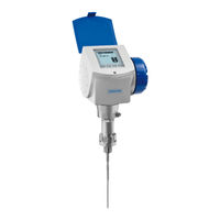
KROHNE OPTIFLEX 1300 C Handbook (196 pages)
Guided Radar (TDR) Level Meter
Brand:
KROHNE
| Category:
Measuring Instruments
| Size: 14 MB
Table of Contents
Table of Contents
3
Safety Instructions
7
Intended Use
7
Certification
7
Safety Instructions from the Manufacturer
7
Disclaimer
7
Product Liability and Warranty
8
Information Concerning the Documentation
8
Display Conventions
9
Safety Instructions for the Operator
9
Instrument Description
10
Scope of Delivery
10
Instrument Description
11
Nameplate
12
Visual Check
12
Non-Ex Nameplate
13
Installation
14
Pre-Installation Requirements
14
General Installation Notes
14
How to Assemble the Single Rod Probe
14
How to Turn or Remove the Signal Converter
17
How to Assemble the Remote Housing
19
Storage
22
Transportation
23
How to Prepare the Tank before You Install the Instrument
24
Pressure and Temperature Ranges
24
General Information for Nozzles
25
Installation Requirements for Concrete Roofs
27
Installation Recommendations for Liquids
28
General Requirements
28
How to Attach Probes to the Bottom of the Tank
29
Installation in Stilling Wells
33
Installation in Bypass Chambers
35
Typical Applications
37
Installation Recommendations for Solids
40
Nozzles on Conical Silos
40
Traction Loads on the Probe
41
How to Install the Instrument on the Tank
42
How to Install an Instrument with a Flange Connection
42
How to Install an Instrument with a Threaded Connection
43
How to Install a Cable Probe in the Tank
44
Installation Recommendations for Non-Metallic Tanks and Pits
45
How to Attach the Weather Protection to the Instrument
46
How to Open the Weather Protection
47
Electromagnetic Compatibility
48
Electrical Connections
49
Safety Instructions
49
Electrical Installation: Outputs 1 and 2
50
Electrical Connection for Current Output
51
Non-Ex
51
Ex I
51
Ex D
52
Protection Category
53
Networks
54
General Information
54
Point-To-Point Networks
54
Multi-Drop Networks
55
Start-Up
56
Start-Up Checklist
56
Operating Concept
56
Digital Display Screen
57
Local Display Screen Layout
57
Push-Button Functions
57
Help Screens
57
How to Start the Instrument
58
Remote Communication with Pactware
58
Remote Communication with the AMS™ Device Manager
59
Operation
60
User Modes
60
Operator Mode
60
Supervisor Mode
62
General Notes
62
How to Get Access to the Supervisor Mode
63
Menu Overview
64
Push-Button Functions
65
Function Description
68
Further Information on Instrument Configuration
85
Quick Links
85
Protection of the Instrument Settings
86
Network Configuration
86
Linearisation
87
Distance Measurement
88
Level Measurement
89
How to Correctly Configure the Instrument to Measure Volume or Mass
90
How to Make the Instrument Follow the Correct Level or Interface Signal
91
Thresholds and Parasite Signals
94
How to Use the Snapshot Function to Filter Parasite Signals that Do Not Move
97
How to Measure Products with a Low Dielectric Constant (E R )
98
How to Decrease the Length of Probes
100
Service Mode
102
Errors
102
General Information
102
Error Handling
104
ATEX: Supplementary Instructions
108
General Safety Information
108
Scope of the Document
108
Instrument Description
108
Standards and Approvals
108
ATEX Nameplates
109
Installation
110
Precautions
110
Operating Conditions
111
Electrical Connections
115
General Notes
115
Terminal Compartment
115
Terminal Tightening Capacity
116
Eex Ia Equipment
116
Eex D [Ia] Equipment
118
Eex Na Equipment
121
Start-Up
122
Service
122
Service
123
Periodic Maintenance
123
Keep the Instrument Clean
123
How to Replace Instrument Components
123
Service Warranty
123
Replacement of the Display Cover
124
Replacement of the Combined Back End and High-Frequency Unit
126
Replacement of the Terminal Module
128
Spare Parts Availability
130
General Notes
130
List of Spare Parts
130
List of Accessories
132
Service Availability
133
Returning the Device to the Manufacturer
134
General Information
134
Form (for Copying) to Accompany a Returned Instrument
135
Disposal
136
Technical Data
137
Pressure/Temperature Table for Probe Selection
141
Measurement Limits
142
Dimensions and Weight
144
Appendices
155
Glossary
155
EC Declaration of Conformity
161
ATEX Approval Certificate
162
Iecex Approval Certificate
168
FM Certificate of Compliance and Control Drawings
173
CSA Certificate of Compliance and Control Drawings
178
Republic of Belarus Certificates
183
Republic of Kazakhstan Certificates
184
Russian Federation Certificates
185
Ukraine Certificates
188
KROHNE Measuring Technology - Product Overview
196
Advertisement
krohne OPTIFLEX 1300 C Handbook (160 pages)
level meter
Brand:
krohne
| Category:
Measuring Instruments
| Size: 7 MB
Table of Contents
Table of Contents
3
1 Safety Instructions
6
Intended Use
6
Certification
6
Electromagnetic Compatibility
6
Safety Instructions from the Manufacturer
7
Copyright and Data Protection
7
Disclaimer
7
Product Liability and Warranty
8
Information Concerning the Documentation
8
Warnings and Symbols Used
9
Safety Instructions for the Operator
9
2 Device Description
10
Scope of Delivery
10
Device Description
12
Visual Check
13
Nameplates
14
Non-Ex Nameplate
14
3 Installation
15
Notes on Installation
15
Storage
16
Transport
17
Pre-Installation Requirements
18
How to Prepare the Tank before You Install the Device
18
Pressure and Temperature Ranges
18
General Information for Nozzles
20
Installation Requirements for Concrete Roofs
22
Installation Recommendations for Liquids
22
General Requirements
22
How to Attach Probes to the Bottom of the Tank
23
Standpipes
26
Typical Applications
31
Installation Recommendations for Solids
33
Nozzles on Conical Silos
33
Traction Loads on the Probe
34
How to Install the Device on the Tank
35
How to Assemble the Single Rod Probe (Single-Piece Probe)
35
How to Assemble the Single Rod Probe (Segmented Probe)
39
How to Assemble the Segmented Coaxial Probe
42
How to Install a Device with a Flange Connection
45
How to Install a Device with a Threaded Connection
46
How to Install a Cable Probe in the Tank
47
Installation Recommendations for Non-Metallic Tanks and Pits
48
How to Assemble the Remote Housing
49
How to Turn or Remove the Signal Converter
52
How to Attach the Weather Protection to the Device
53
How to Open the Weather Protection
54
4 Electrical Connections
55
Safety Instructions
55
Electrical Installation: Outputs 1 and 2
55
Electrical Connection for Current Output
56
Non-Ex
56
Ex I
56
Ex D
56
Profibus Pa
57
FOUNDATION Fieldbus
57
Protection Category
57
Networks
58
General Information
58
Point-To-Point Networks
58
Multi-Drop Networks
59
Fieldbus Networks
60
5 Start-Up
62
Start-Up Checklist
62
Operating Concept
62
Digital Display Screen
63
Local Display Screen Layout
63
Keypad Buttons
63
Help Screens
63
How to Start the Device
64
Remote Communication with Pactware
64
Remote Communication with the AMS™ Device Manager
65
6 Operation
66
User Modes
66
Operator Mode
66
Supervisor Mode
69
General Notes
69
How to Get Access to the Supervisor Mode
69
Menu Overview
70
Keypad Functions
71
Function Description
74
Further Information on Device Configuration
89
Quick Links
89
Protection of the Device Settings
90
Network Configuration
91
Linearisation
92
Distance Measurement
92
Level Measurement
93
How to Configure the Device to Measure Volume or Mass
94
How to Make the Device Follow the Correct Level or Interface Signal
95
Thresholds and Parasitic Signals
97
How to Use the Snapshot Function to Filter Parasitic Signals
101
How to Measure Products with a Low Dielectric Constant (E R )
102
How to Decrease the Length of Probes
103
Service Mode
104
Errors
105
General Information
105
Error Handling
107
7 Service
111
Periodic Maintenance
111
Keep the Device Clean
111
How to Replace Device Components
111
Service Warranty
111
Replacement of the Display Cover
112
Replacement of the Complete Electonic Module
114
Replacement of the Terminal Module
116
Spare Parts Availability
118
List of Spare Parts
118
List of Accessories
120
Availability of Services
122
Returning the Device to the Manufacturer
122
General Information
122
Form (for Copying) to Accompany a Returned Device
123
Disposal
124
8 Technical Data
125
Measuring Principle
125
Technical Data
128
Input and Output
131
Pressure/Temperature Table for Probe Selection
134
Measurement Limits
135
Dimensions and Weights
138
9 Appendix
152
Order Form
152
Device Data
152
Rating Data
153
Contact Data
153
Glossary
153
10 Notes
158
krohne OPTIFLEX 1300 C Quick Start Manual (44 pages)
Guided Radar (TDR) Level Meter
Brand:
krohne
| Category:
Test Equipment
| Size: 2 MB
Table of Contents
Table of Contents
2
1 Safety Instructions
4
2 Installation
5
Intended Use
5
Scope of Delivery
5
Visual Check
7
Storage
8
Transport
9
Pre-Installation Requirements
10
How to Prepare the Tank before You Install the Device
10
Pressure and Temperature Ranges
10
General Information for Nozzles
12
Installation Requirements for Concrete Roofs
14
Installation Recommendations for Liquids
14
General Requirements
14
How to Attach Probes to the Bottom of the Tank
15
Standpipes
15
Installation Recommendations for Solids
16
Nozzles on Conical Silos
16
Traction Loads on the Probe
18
How to Install the Device on the Tank
18
How to Assemble the Single Rod Probe (Single-Piece Probe)
18
How to Assemble the Single Rod Probe (Segmented Probe)
18
How to Assemble the Segmented Coaxial Probe
18
How to Install a Device with a Flange Connection
19
How to Install a Device with a Threaded Connection
20
How to Install a Cable Probe in the Tank
21
Installation Recommendations for Non-Metallic Tanks and Pits
22
How to Assemble the Remote Housing
23
How to Turn or Remove the Signal Converter
26
How to Attach the Weather Protection to the Device
27
How to Open the Weather Protection
28
Electromagnetic Compatibility
29
3 Electrical Connections
30
Safety Instructions
30
Electrical Installation: Outputs 1 and 2
30
Electrical Connection for Current Output
31
Non-Ex
31
Ex I
31
Ex D
31
Profibus Pa
32
FOUNDATION Fieldbus
32
Protection Category
32
4 Start-Up
33
Start-Up Checklist
33
Operating Concept
33
Digital Display Screen
34
Local Display Screen Layout
34
Keypad Buttons
34
Help Screens
34
How to Start the Device
35
Remote Communication with Pactware
35
Remote Communication with the AMS™ Device Manager
36
5 Technical Data
37
Measurement Limits
43
Advertisement
KROHNE OPTIFLEX 1300 C Quick Start Manual (48 pages)
2-wire / Guided Radar (TDR) Level Meter
Brand:
KROHNE
| Category:
Measuring Instruments
| Size: 3 MB
Table of Contents
Table of Contents
2
1 Safety Instructions
3
2 Installation
4
Intended Use
4
Scope of Delivery
4
Visual Check
6
Storage
7
Transport
8
Pre-Installation Requirements
9
How to Prepare the Tank before You Install the Device
9
Pressure and Temperature Ranges
9
General Information for Nozzles
11
Installation Requirements for Concrete Roofs
13
Installation Recommendations for Liquids
14
General Requirements
14
How to Attach Probes to the Bottom of the Tank
15
Standpipes
15
Installation Recommendations for Solids
15
Nozzles on Conical Silos
15
Traction Loads on the Probe
17
How to Install the Device on the Tank
18
How to Assemble the Single Rod Probe (Single-Piece Probe)
18
How to Assemble the Single Rod Probe (Segmented Probe)
22
How to Assemble the Segmented Coaxial Probe
25
How to Install a Device with a Flange Connection
28
How to Install a Device with a Threaded Connection
29
How to Install a Cable Probe in the Tank
30
Recommendations for Pits and Tanks Made of Non-Conductive Materials
31
How to Assemble the Remote Version
32
How to Turn or Remove the Signal Converter
35
How to Attach the Weather Protection to the Device
36
How to Open the Weather Protection
37
Electromagnetic Compatibility
38
3 Electrical Connections
39
Safety Instructions
39
Electrical Installation: Outputs 1 and 2
39
Electrical Connection for Current Output
40
Non-Ex Devices
40
Devices for Hazardous Locations
40
Protection Category
41
4 Technical Data
42
Measurement Limits
47
KROHNE OPTIFLEX 1300 C Supplementary Instructions Manual (12 pages)
FOUNDATION Fieldbus communication.
Brand:
KROHNE
| Category:
Transmitter
| Size: 0 MB
Table of Contents
Table of Contents
2
1 General Safety Information
3
Scope of the Document
3
Device Description
3
Scope of Delivery
3
2 FOUNDATION Fieldbus Data
4
3 Electrical Connections
5
Electrical Installation: Terminals
5
Electrical Connection: Pactware
6
4 Operation
7
Description of Device Data
7
Resource Block
7
Transducer Block
7
Measurement Data
8
Status Data
8
5 Notes
9
Advertisement
Related Products
KROHNE OPTIFLEX 1100 C
KROHNE OPTIMASS 1010C
KROHNE OPTIMASS 1000 T6
KROHNE OPTIMASS 1010C T6
KROHNE OPTIMASS 1300C T6
KROHNE VERSAFLOW SONIC 1000/TWS 9000
KROHNE OPTIFLEX 8200 C
KROHNE OPTIFLEX 8200 F
KROHNE OPTIFLEX 8200 S
KROHNE OPTIFLEX 200 Series
krohne Categories
Measuring Instruments
Transmitter
Switch
Accessories
Media Converter
More krohne Manuals
Login
Sign In
OR
Sign in with Facebook
Sign in with Google
Upload manual
Upload from disk
Upload from URL