Sign In
Upload
Manuals
Brands
Juniper Manuals
Network Router
M5
Juniper M5 Manuals
Manuals and User Guides for Juniper M5. We have
3
Juniper M5 manuals available for free PDF download: Hardware Manual, Quick Reference, Installation, Quick Start
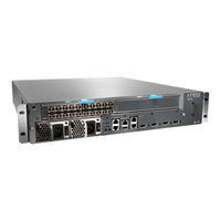
Juniper M5 Hardware Manual (205 pages)
Juniper Router Hardware Guide
Brand:
Juniper
| Category:
Network Router
| Size: 3.02 MB
Table of Contents
Table of Contents
3
About this Manual
15
Objectives
15
Audience
15
Document Organization
15
Documentation Conventions
16
General Conventions
16
List of Technical Publications
17
Notes, Cautions, and Warnings
17
Table 1: Juniper Networks Technical Documentation
17
Documentation Feedback
19
How to Request Support
19
Product Overview
21
Figure 12: System Architecture
21
Part
21
Chapter 1 System Overview
23
System Description
23
Field-Replaceable Units (Frus)
23
Part
23
Safety Requirements, Warnings, and Guidelines
24
Table 2: Field-Replaceable Units
24
Part
24
Chapter 2 Hardware Component Overview
25
Chassis
25
Figure 1: Front of M5 Chassis
26
Figure 2: Front of M10 Chassis
26
Figure 3: Rear of Chassis
27
Table 3: Chassis Physical Specifications
27
Packet Forwarding Engine
28
Midplane
28
Physical Interface Cards (Pics)
29
Figure 4: Midplane
29
Flexible PIC Concentrators (Fpcs)
30
Forwarding Engine Board (FEB)
30
PIC Components
30
FEB Components
31
Routing Engine
32
Figure 5: Forwarding Engine Board
32
Routing Engine Components
33
Craft Interface
34
Figure 6: Routing Engine
34
Figure 7: Craft Interface
34
Alarm Leds and Lamp Test Button
35
Routing Engine Interface Ports and Status Indicators
35
Table 4: Alarm Leds and Lamp Test Button
35
PIC Offline Buttons
36
Power Supplies
36
AC Power Supply
37
Figure 8: AC Power Supply
37
DC Power Supply
38
Figure 9: DC Power Supply
38
Table 5: Electrical Specifications for AC Power Supply
38
Table 6: Electrical Specifications for DC Power Supply
38
Power Supply Leds and Self-Test Button
39
Fan Tray
39
Figure 10: Airflow through the Chassis
39
Table 7: States for Power Supply LED
39
Cable Management System
40
Figure 11: Cable Management System
40
Chapter 3 JUNOS Internet Software Overview
41
Routing Engine Software Components
41
Routing Protocol Process
42
Ipv4 Routing Protocols
42
Ipv6 Routing Protocols
44
Routing and Forwarding Tables
44
Routing Policy
45
Chassis Process
46
Interface Process
46
SNMP and MIB II Processes
46
Vpns
46
Management Process
47
Routing Engine Kernel
47
Tools for Accessing and Configuring the Software
47
Tools for Monitoring the Software
47
Software Upgrades
48
Chapter 4 System Architecture Overview
49
Packet Forwarding Engine Architecture
49
Data Flow through the Packet Forwarding Engine
50
Routing Engine Architecture
51
Figure 13: Packet Forwarding Engine Components and Data Flow
51
Figure 14: Routing Engine Architecture
52
Routing Engine Functions
52
Figure 15: Control Packet Handling for Routing and Forwarding Table Updates
53
Initial Installation
55
Part
55
Chapter 5 Prepare for Router Installation
57
Rack Requirements
57
Rack Size and Strength
57
Spacing of Mounting Holes
59
Connection to Building Structure
59
Figure 16: Typical Center-Mount Rack
59
Clearance Requirements for Airflow and Hardware Maintenance
60
Router Environmental Tolerances
60
Figure 17: Chassis Dimensions and Clearance Requirements
60
Table 8: Router Environmental Tolerances
60
Fire Safety Requirements
61
Fire Suppression
61
Fire Suppression Equipment
61
M5 and M10 Internet Routers Hardware Guide
62
Power Guidelines, Requirements, and Specifications
62
Distance Limitations for Signaling
63
Electromagnetic Compatibility
63
Radio Frequency Interference
63
Router Power Requirements
63
Site Electrical Wiring Guidelines
63
Table 9: Component Power Requirements
64
AC Grounding and Power Cord Specifications
65
Table 10: AC Power Cord Specifications
65
DC Grounding, Connection, and Cable Specifications
66
Figure 18: AC Plug Types
66
Table 11: DC Power and Grounding Cable Specifications
66
Figure 19: DC Power and Grounding Cable Connections
67
Fiber Optic and Network Cable Specifications
68
Network Cable Specifications and Guidelines
68
Signal Loss in Multimode and Single-Mode Fiber-Optic Cable
68
Attenuation and Dispersion in Fiber-Optic Cable
69
Calculating Power Budget for Fiber-Optic Cable
69
Calculating Power Margin for Fiber-Optic Cable
70
Table 12: Estimated Values for Factors Causing Link Loss
70
Attenuate to Prevent Saturation at SONET/SDH Pics
71
Cable Specifications for Routing Engine Management Interfaces
72
Site Preparation Checklist
72
Table 13: Cable Specifications for Routing Engine Management Interfaces
72
Table 14: Site Preparation Checklist
72
Chapter 6 Unpack the Router
75
Tools Required
75
Unpack the Router
75
Figure 20: Unpack the Router
75
Table 15: Generic Inventory of Router Components
76
Choose Front or Center Mounting
77
Chapter 7 Install the Router
79
Tools and Parts Required
79
Install the Chassis into the Rack
79
Chapter 8 Connect the Router and Perform Initial Configuration
81
Tools and Parts Required
81
Connect the Router to Management Devices
81
Connect to a Network for Out-Of-Band Management
82
Figure 21: Routing Engine Management Ports
82
Connect to a Management Console or Auxiliary Device
83
Connect PIC Cables
83
Figure 22: Routing Engine Ethernet Cable Connector
83
Figure 23: Console and Auxiliary Serial Port Connector
83
Provide Power to the Router
85
Connect Power to an AC-Powered Router
85
Figure 24: Attach Cable to a PIC
85
Connect Power to a DC-Powered Router
86
Figure 25: Connect DC Power and Grounding Cables
87
Power on the Router
87
Configure the JUNOS Internet Software
89
Hardware Maintenance, Replacement, and Troubleshooting
93
Procedures
93
Chapter 9 Maintain Hardware Components
95
Routine Maintenance Procedures
95
Maintain the Fan Tray
95
Maintain Packet Forwarding Engine Components
96
Maintain the FEB
96
Maintain Pics and PIC Cables
96
Maintain the Power Supplies
98
Maintain the Routing Engine
99
Chapter 10 Replace Hardware Components
101
Tools and Parts Required
101
Table 16: Tools and Parts Required
101
Replace the Fan Tray
102
Remove the Fan Tray
102
Install the Fan Tray
103
Figure 26: Remove the Fan Tray
103
Replace Packet Forwarding Engine Components
104
Figure 27: Install the Fan Tray
104
Replace the FEB
104
Remove the FEB
105
Figure 28: Remove the FEB
106
Install the FEB
106
Figure 29: Install the FEB
107
Remove a PIC
107
Replace a PIC
107
Figure 30: Remove a PIC
109
Install a PIC
109
Figure 31: Install a PIC
112
Remove a PIC Cable
112
Replace PIC Cables
112
Install a PIC Cable
113
Figure 32: Connect Fiber-Optic Cable to a PIC
115
Figure 33: Small Form Factor Pluggable (SFP)
115
Remove an SFP
115
Replace an SFP
115
Install an SFP
116
Replace Power System Components
118
Replace an AC Power Supply
118
Remove an AC Power Supply
119
Figure 34: Remove an AC Power Supply
120
Install an AC Power Supply
120
Disconnect and Connect AC Power
121
Figure 35: Install an AC Power Supply
121
Connect AC Power to the Router
122
Disconnect AC Power from the Router
122
Replace an AC Power Cord
123
Remove a DC Power Supply
124
Replace a DC Power Supply
124
Figure 36: Remove a DC Power Supply
126
Install a DC Power Supply
126
Disconnect and Connect DC Power
128
Figure 37: Install a DC Power Supply
128
Figure 38: Connect Power Cables to a DC Power Supply
128
Disconnect DC Power from the Router
129
Connect DC Power to the Router
130
Replace Routing Engine Components
132
Figure 39: Connect Power Cables to a DC Power Supply
132
Remove and Insert the PC Card
132
Remove the PC Card
133
M5 and M10 Internet Routers Hardware Guide
134
Insert the PC Card
134
Figure 40: Remove the PC Card
134
Figure 41: Insert the PC Card
135
Remove the Routing Engine
135
Replace the Routing Engine
135
Figure 42: Remove the Routing Engine
136
Install the Routing Engine
136
Figure 43: Install the Routing Engine
138
Figure 44: Routing Engine Interface Ports and Alarm Relay Contacts
138
Replace Connectors to Routing Engine Interface Ports
138
Replace the Management Ethernet Cable
138
Figure 45: Ethernet Cable Connector
139
Replace the Console or Auxiliary Cable
139
Figure 46: Serial Port Connector
140
Chapter 11 Troubleshoot Hardware Components
141
Overview of Troubleshooting Resources
141
Command-Line Interface
141
Leds
142
Hardware and Interface Alarm Messages
142
Leds on Hardware Components
142
Leds on the Craft Interface
142
Table 17: Chassis Alarm Messages
143
Table 18: SONET/SDH Interface Alarm Messages
143
Juniper Networks Technical Assistance Center
144
Troubleshoot the Fan Tray
144
Troubleshoot Packet Forwarding Engine Components
144
Troubleshoot Pics
145
Troubleshoot the FEB
145
Troubleshoot the Power System
145
LED on both Supplies Is off
146
LED on One Supply Is off
146
Appendixes
147
Appendix A Safety and Regulatory Compliance Information
149
Definition of Safety Warning Levels
149
Safety Guidelines and Warnings
151
General Safety Guidelines and Warnings
151
Qualified Personnel Warning
152
Restricted Access Area Warning
153
Prevent Electrostatic Discharge Damage
154
Electrical Safety Guidelines and Warnings
155
Figure 47: Place a Component into an Electrostatic Bag
155
AC Power Electrical Safety Guidelines
156
General Electrical Safety Guidelines
156
DC Power Electrical Safety Guidelines
157
Copper Conductors Warning
158
DC Power Disconnection Warning
158
DC Power Grounding Requirements and Warning
159
DC Power Wiring Sequence Warning
160
DC Power Wiring Terminations Warning
161
Grounded Equipment Warning
162
In Case of Electrical Accident
163
Midplane Energy Hazard Warning
163
Multiple Power Supplies Disconnection Warning
164
Power Disconnection Warning
164
TN and IT Power Warning
165
Chassis Lifting Guidelines
166
Installation Safety Guidelines and Warnings
166
Installation Instructions Warning
167
Rack-Mounting Requirements and Warnings
167
Ramp Warning
171
General Laser Safety Guidelines
172
Laser and LED Safety Guidelines and Warnings
172
Class 1 Laser Product Warning
173
Class 1 LED Product Warning
173
Laser Beam Warning
174
Radiation from Open Port Apertures Warning
174
Battery Handling Warning
175
Maintenance and Operational Safety Guidelines and Warnings
175
Jewelry Removal Warning
176
Lightning Activity Warning
177
Operating Temperature Warning
178
Product Disposal Warning
179
Agency Approvals
180
Compliance Statements for EMC Requirements
181
Canada
181
European Community
181
Japan
181
Taiwan
181
United States
182
Tools and Parts Required
183
Return Procedure
183
Locate Component Serial Numbers
184
FEB Serial Number ID Label
185
Figure 48: Serial Number ID Label
185
Figure 49: FEB Serial Number ID Label
185
PIC Serial Number ID Label
185
Figure 50: PIC Serial Number ID Label
186
Figure 51: AC Power Supply Serial Number ID Label
186
Power Supply Serial Number ID Label
186
Figure 52: DC Power Supply Serial Number ID Label
187
Figure 53: Routing Engine 333 Serial Number ID Label
187
Routing Engine Serial Number ID Label
187
Pack the Router for Shipment
188
Figure 54: Routing Engine 600 Serial Number ID Label
188
Pack Components for Shipment
189
Appendix B Return the Router or Its Components
183
Appendix C Cable Connector Pinouts
191
RJ-45 Connector Pinouts for the Routing Engine MGMT Port
191
DB-9 Connector Pinouts for the Routing Engine AUX/MODEM and CONSOLE Ports
191
Table 19: RJ-45 Connector Pinout
191
RJ-48 Cable Pinouts for E1 and T1 Pics
192
Table 20: DB-9 Connector Pinout
192
Table 21: RJ-48 Connector to RJ-48 Connector (Straight) Pinout
192
Table 22: RJ-48 Connector to RJ-48 Connector (Crossover) Pinout
193
Table 23: RJ-48 Connector to DB-15 Connector (Straight) Pinout
194
Table 24: RJ-48 Connector to DB-15 Connector (Crossover) Pinout
194
RJ-21 Cable Pinouts for Fast Ethernet 12-Port PIC
195
Figure 55: Fast Ethernet 12-Port PIC
195
Figure 56: VHDCI to RJ-21 Cable
195
Table 25: RJ-21 Pin Assignments
196
Part
197
Index
197
Advertisement
Juniper M5 Quick Reference (4 pages)
Internet Backbone Routers
Brand:
Juniper
| Category:
Network Router
| Size: 0.19 MB
Juniper M5 Installation, Quick Start (2 pages)
Internet Routers
Brand:
Juniper
| Category:
Network Router
| Size: 0.34 MB
Advertisement
Advertisement
Related Products
Juniper M40
Juniper M40e
Juniper M7i
Juniper M320
Juniper MX240
Juniper MX2020
Juniper MX5
Juniper MX10
Juniper MX80
Juniper MX10008
Juniper Categories
Network Router
Switch
Gateway
Software
Network Hardware
More Juniper Manuals
Login
Sign In
OR
Sign in with Facebook
Sign in with Google
Upload manual
Upload from disk
Upload from URL