Sign In
Upload
Manuals
Brands
JAI Manuals
Security Camera
AD-131GE
JAI AD-131GE Manuals
Manuals and User Guides for JAI AD-131GE. We have
1
JAI AD-131GE manual available for free PDF download: User Manual
JAI AD-131GE User Manual (92 pages)
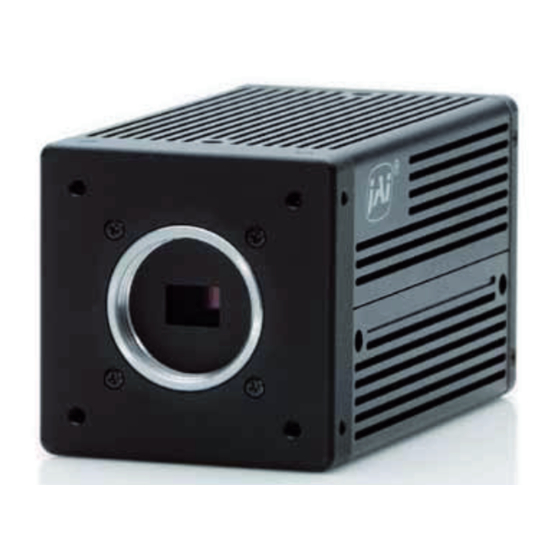
Digital 2CCD Progressive Scan HDR / High Frame Rate Camera
Brand:
JAI
| Category:
Security Camera
| Size: 3 MB
Table of Contents
Table of Contents
4
Vision Camera Operation Manuals
8
Introduction
8
Before Using Gige Vision Camera
8
Software Installation
8
Camera Operation
9
General
9
Camera Nomenclature
9
Main Features
10
Locations and Functions
11
Rear Panel Indicator
12
Pin Configuration & DIP Switch
13
12-Pin Multi-Connector (DC-In/Gpio/Iris Video)
13
Digital Output Connector for Gigabit Ethernet
13
6-Pin Multi-Connector (LVDS in and TTL IN/OUT)
13
DIP Switches
14
SW800 Trigger Input 75 Ohms Termination
14
SW100 Ttl/Open Collector Output Select
14
SW700 Video Output for Auto Iris Lens
14
System Configuration
15
System Connection
15
Outputs
15
Sync Mode
16
Inputs and Outputs Interface
17
Overview
17
LUT (Cross Point Switch)
17
12-Bit Counter
18
Pulse Generators (0 to 3)
18
Opto-Isolated Inputs/Outputs
18
Recommended External Input Circuit Diagram for Customer
18
Recommended External Output Circuit Diagram for Customer
19
Optical Interface Specifications
19
Input and Output Circuits
20
Iris Video Output
20
Iris Video Input and Output
20
Iris Video Output Select
20
Trigger Input
21
Exposure Enable (EEN) Output
21
GPIO Inputs and Outputs Table
22
Configuring the GPIO Module
23
Input /Output Signal Selector
23
Pulse Generators (20 Bit X 4)
23
GPIO Interface in Genicam Standard
24
Change Polarity
24
Restrictions to the Use of TTL in I/F in the AD-131GE
25
Caution When the Software Trigger Is Used
26
GPIO Programming Examples
28
GPIO Plus PWC Shutter
28
Internal Trigger Generator
29
Video Signal Output
30
Sensor Layout
30
Partial Scan (JAI Partial Scan ON)
31
Digital Video Output (Bit Allocation)
32
AD-131GE Pixel Format / Pixel Type
32
GVSP_PIX_MONO8 (8Bit)
32
GVSP_PIX_MONO10 (10Bit)
32
GVSP_PIX_MONO10_PACKED (10 Bit)
32
GVSP_PIX_MONO12 (12 Bit)
33
GVSP_PIX_MONO12_PACKED (12 Bit)
33
Video Timing
33
Horizontal Timing
33
Vertical Timing
34
Partial Scan Vertical Timing
35
Binning Scan Vertical Timing
36
Network Configuration
37
Gige Vision Standard Interface
37
Equipment to Configure the Network System
37
Cables
37
Network Card (NIC)
37
Hub
38
Recommended Network Configurations
38
Guideline for Network Settings
38
Video Data Rate (Network Bandwidth)
39
Simplified Calculation (Approximate Value)
40
Note for 100BASE-TX Connection
40
Gige Camera Connecting Examples
41
Using a Switching Hub for 1 Port
41
Connecting a Camera to each Port of a Multi-Port NIC
41
The Data Transfer for Multiple Cameras
42
If Delayed Readout Is Not Used in Continuous Mode
42
If Delayed Readout Is Not Used in Trigger Mode
42
If Delayed Readout Is Used
43
Functions (Conforming to Genicam SFNC 1.3)
44
Acquisition Function
44
Basic Image Acquisition Flow
44
Acquisition Mode
45
Single Frame
45
Continuous Mode
46
Trigger Control
47
Trigger Selector (Trigger Mode)
47
Acquisition
47
Exposure
47
Trigger Software
48
10.2.3 Trigger Source
48
10.2.4 Trigger Activation
48
Exposure Control
48
Exposure Mode
48
Exposure Time
49
10.3.3 Exposure Auto
49
Action Control
49
Actiondevicekey
50
Actionselector
50
Actiongroupmask
50
Actiongroupkey
50
Operation Mode
50
High Frame Rate Mode (Double Speed)
50
High Dynamic Range Mode
51
High S/N Mode
52
Setting Matrix for Sync Mode and Exposure Mode(JAI)
53
Trigger Operation Mode
53
The Exposure Timing When the Trigger Pulse Is Input
54
Auto-Detect LVAL-Sync / Async Accumulation
54
Relation between the External Trigger Mode and LVAL Sync/Async
54
Continuous Mode
55
Trigger Operation with Pre-Select Exposure Time (EPS)
55
Timing Chart
57
Trigger Operation Controlled by Pulse Width (PWC)
59
Timing Chart
60
Smearless Mode
61
Sync=Sync, LVAL Async, Smearless Enable=True, EPS Trigger
61
Sync Mode=Sync, LVAL Async, Smearless Enable=True, PWC Trigger
62
Reset Continuous Trigger (RCT) Mode
63
PIV ( Particle Image Velocimetry ) Mode
64
Relation between Exposure and Video Readout
65
Relation between PIV Exposure and PIV Interval
65
Preset Value Table for PIV 1, 2 and 3
66
Setting Values and Range for PIV 4
66
Formula from PIV Exposure and Interval to Exposure Time and Interval
66
PIV Trigger Minimum Interval
67
Sequential Trigger Mode (EPS)
68
Setting Parameters
68
Initial Settings
69
Delayed Readout EPS and PWC Modes
70
Multi ROI Mode (Multi Region of Interest)
70
Setting Parameters
71
Initial Parameters
71
Optical Black Transfer Mode
71
Operation Mode and Functions Matrix
73
Other Functions
74
Basic Functions
74
2CCD Optical Assembly
74
Electronic Shutter
74
Shading Correction
76
Blemish Compensation
77
Alc
77
Test Signal Generator
79
Control Tool Screen
79
External Appearance and Dimensions
85
Specifications
86
Total Spectral Response Including Prism and CCD
86
Specification Table
87
Appendix
89
Precautions
89
Typical Sensor Characteristics
89
Caution When Mounting a Lens on the Camera
89
Caution When Mounting the Camera
90
Exportation
90
References
90
Change History
91
User's Record
92
Advertisement
Advertisement
Related Products
JAI AD-081GE
JAI AT-140GE
JAI AT-200GE
Jai AT-200CL
JAI AB-200CL
JAI AM-200CL
JAI AT-030MCL
JAI AB-201CL
JAI AM-201CL
JAI AD-130GE
JAI Categories
Digital Camera
Security Camera
Machine Vision Systems
CCD Cameras
Color Camera
More JAI Manuals
Login
Sign In
OR
Sign in with Facebook
Sign in with Google
Upload manual
Upload from disk
Upload from URL