Sign In
Upload
Manuals
Brands
ICOM Manuals
Transceiver
IC-756PROII
ICOM IC-756PROII Manuals
Manuals and User Guides for ICOM IC-756PROII. We have
4
ICOM IC-756PROII manuals available for free PDF download: Service Manual, Instruction Manual
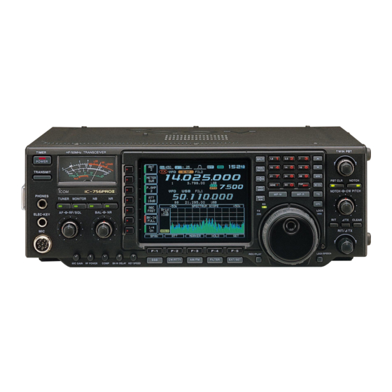
Icom IC-756PROII Service Manual (119 pages)
HF/50MHz ALL BAND TRANSCEIVER
Brand:
Icom
| Category:
Transceiver
| Size: 20.54 MB
Table of Contents
Danger
2
Introduction
2
Ordering Parts
2
Repair Notes
2
Table of Contents
3
Specifications
4
Antenna Tuner
4
Inside Views
5
Top View
5
Bottom View
6
Circuit Description
7
Receiver Circuit
7
Rf Switching Circuit
7
Pre-Amplifier Circuits
7
1St if Circuit
8
2Nd Mixer Circuit
8
2Nd if Circuit
8
3Rd Mixer and 3Rd if Circuits
8
S-Meter Circuit (Main-A Unit)
9
Squelch Circuit (Main-A Unit)
9
Twin Pbt Circuit (Dsp-A Board)
9
Agc Circuit (Dsp-A Board)
9
Transmitter Circuits
10
Microphone Amplifier Circuit
10
Vox Circuit
10
When FM/AM Modes
10
Speech Compressor Circuit
11
If Amplifier and Mixer Circuits
11
Rf Circuit (Rf-B and Pa Units)
11
Low-Pass Filter Circuit (Filter-A Unit)
11
Monitor Circuit
12
Pll Circuits
12
Apc Circuit (Main-A Unit)
12
When SSB/RTTY Modes (DSP-A BOARD)
12
2Nd lo and Reference Oscillator Circuits
13
3Rd lo Circuit
13
Marker Circuit
13
Reference Loop Pll
13
Antenna Tuner Circuits
14
Matching Circuit (Tuner-A Unit)
14
Detector Circuit (Ctrl-A Unit)
14
Antenna Tuner Cpu Port Allocation
14
Scope Circuits
15
Scope Receiver Circuit (Rf-B Unit)
15
Power Supply Circuits
15
Sweep lo Circuit (Pll Unit)
15
Sub-Cpu Port Allocations
16
Main-A Unit
16
Ctrl-A and Pll Units
16
Logic Circuits
16
Main-Cpu Port Allocations
17
Input Expander Allocations
18
Adjustment Procedures
21
Preparation
21
Required Test Equipment
21
Connections
21
Pll Adjustments
22
PLL Unit
23
Bottom View of the Transceiver
23
Transmitter Adjustments
24
PA Unit
25
RF-B Unit
25
DSP-A Board
27
Receiver Adjustments
28
Rx Peak
28
Mixer Balance
28
Tuner Adjustments
32
CTRL-A Unit
32
Meter Adjustments
33
Parts List
35
Display Unit
36
Pll Unit
39
Key Unit
39
MIC Unit
39
Section 8 Board Layouts
66
Section 7 Semi-Conductor Information
66
Mechanical Parts and Disassembly
66
Display Board
66
MIC Board
66
Phone Board
66
Rit Board
66
Semi-Conductor Information
70
Transistors and Fet’s
70
Diodes
71
Board Layouts
72
Display Board
72
Display Board (Bottom View)
73
Key Board
74
Mode Board
74
Phone Board
74
Ten-Key Board
74
Key Board (Bottom View)
75
Phone Board (Bottom View)
75
Ten-Key Board (Bottom View)
75
Memory Board
76
MIC Board
76
Pbt Board
76
Rit Board
76
Memory Board (Bottom View)
77
MIC Board (Bottom View)
77
Pbt Board (Bottom View)
77
Rit Board (Bottom View)
77
Main-A Unit
78
Dsp-A Board
80
Dsp-A Board (Bottom View)
81
Rf-B Unit
82
Bpf-A Board
84
Preamp Board
84
Bpf-A Board (Bottom View)
85
Preamp Board (Bottom View)
85
Pll Unit
86
Pll Unit (Bottom View)
87
Pa Unit
88
Filter-A Unit
90
Block Diagram
96
Ctrl-A Unit
97
Section 9 Block Diagram
98
Voltage Diagrams
98
Front Unit
98
Dsp-A Board
100
Tuner-A, Memory Boards and Ctrl-A Unit
102
Main-A Unit
104
Pll Unit
109
Pa and Filter-A Units
112
Main Dial
113
Mode Board
113
Bpf-A, Preamp Boards and Rf-B Unit
114
Advertisement
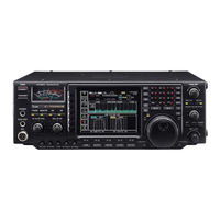
Icom IC-756PROII Instruction Manual (88 pages)
HF/50 MHz ALL MODE TRANSCEIVER
Brand:
Icom
| Category:
Transceiver
| Size: 1.61 MB
Table of Contents
Explicit Definitions
2
Precautions
2
1 Table of Contents
3
2 Panel Description
4
Front Panel
4
Microphone (HM-36)
11
LCD Display
12
Screen Menu Arrangement
14
Panel Description
15
3 Installation and Connections
16
Unpacking
16
Selecting a Location
16
Grounding
16
Antenna Connection
16
Required Connections
17
Advanced Connections
18
Power Supply Connections
19
Linear Amplifier Connections
20
External Antenna Tuner Connections
21
Transverter Jack Information
21
FSK and AFSK (SSTV) Connections
22
4 Frequency Setting
23
When First Applying Power (CPU Resetting)
23
Initial Settings
23
VFO Description
24
Frequency Setting with the Tuning Dial
25
Direct Frequency Entry with the Keypad
25
Advanced Tuning Functions
26
5 Receive and Transmit
27
Mode Selection
27
Twin PBT Operation
27
Notch Function
28
Noise Reduction
28
Noise Blanker
29
DSP Filter Shape
29
RTTY Filter/Twin Peak Filter
30
CW Reverse Mode
30
RTTY Reverse Mode
30
CW Pitch Control
31
IF Filter Selection
31
AGC Function
32
Dualwatch Operation
33
Split Frequency Operation
34
Quick Split Function
35
RIT and ∂TX
36
Monitor Function
37
VOX Function
37
Meter Function
38
SWR Reading
38
Speech Compressor
39
Preamp
39
Digital Voice Recorder
40
Recording a Message for Transmit
42
RTTY Decoder
44
RTTY Tuning Meter
44
Electronic CW Keyer
45
Ant Bw Sftt
45
Memory Keyer
46
Spectrum Scope Screen
47
Att off
47
BW 2.4K SFTT
47
METER Po
47
Qw:pp
47
Usb
47
Vfo Usb Fil2
47
Automatic Antenna Selection
48
Dial Lock Function
48
Repeater Operation
49
Tone Squelch Operation
50
Antenna Tuner Operation
51
Optional External Tuner Operation
52
Receive and Transmit
52
6 Memory Operation
53
Memory Channels
53
Memory Channel Selection
53
Memory Channel Screen
54
Memory Channel Programming
55
Frequency Transferring
56
Memory Names
57
Memory Clearing
57
Memo Pads
58
Memory Operation
58
7 Scans
59
Scan Types
59
Preparation
59
Programmed Scan Operation
60
F Scan Operation
60
Fine Programmed Scan/Fine ∂F Scan
61
Memory Scan Operation
61
Select Memory Scan Operation
62
Setting Select Memory Channels
62
Scan Set Mode
63
Tone Scan
64
8 Clock and Timers
65
Setting the Current Time
65
Timer Function Activity
65
Setting Power-On Time
66
Setting Power-Off Period
66
Timer Operation
66
Clock and Timers
66
9 Set Mode
67
Set Mode Description
67
Level Set Mode
68
Display Set Mode
69
DSP Filter Set Mode
70
Timer Set Mode
71
Miscellaneous (Others) Set Mode
72
Set Mode
77
10 Option Installation
78
Opening the Transceiver's Case
78
Voice Synthesizer Unit
78
11 Maintenance
79
Troubleshooting
79
Fuse Replacement
80
Clock Backup Battery Replacement
80
Tuning Dial Brake Adjustment
81
Frequency Calibration (Approximate)
81
Maintenance
81
12 Internal Views
82
13 Control Command
83
Remote Jack (CI-V) Information
83
Control Command
84
14 Specifications
85
15 Options
86
16 About Ce
87
ICOM IC-756PROII Instruction Manual (88 pages)
HF/50 MHz ALL MODE TRANSCEIVER
Brand:
ICOM
| Category:
Transceiver
| Size: 1.95 MB
Table of Contents
Explicit Definitions
2
Precautions
2
1 Table of Contents
3
2 Panel Description
4
I Front Panel
4
I Microphone (HM-36)
11
I LCD Display
12
I Screen Menu Arrangement
13
I Rear Panel
14
Panel Description ........... 2
15
3 Installation and Connections
16
I Unpacking
16
I Selecting a Location
16
I Grounding
16
I Antenna Connection
16
I Required Connections
17
I Advanced Connections
18
I Power Supply Connections
19
I Linear Amplifier Connections
20
I External Antenna Tuner Connections
21
I Transverter Jack Information
21
I FSK and AFSK (SSTV) Connections
22
4 Frequency Setting
23
I When First Applying Power (CPU Resetting)
23
I Initial Settings
23
I VFO Description
24
I Frequency Setting with the Tuning Dial
25
I Direct Frequency Entry with the Keypad
25
I Advanced Tuning Functions
26
5 Receive and Transmit
27
I Mode Selection
27
I Twin PBT Operation
27
I Notch Function
28
I Noise Reduction
28
I Noise Blanker
29
I DSP Filter Shape
29
I RTTY Filter/Twin Peak Filter
30
I CW Reverse Mode
30
I RTTY Reverse Mode
30
I CW Pitch Control
31
I if Filter Selection
31
I AGC Function
32
I Dualwatch Operation
33
I Split Frequency Operation
34
I Quick Split Function
35
I RIT and ∂TX
36
I Monitor Function
37
I VOX Function
37
I Meter Function
38
I SWR Reading
38
I Speech Compressor
39
I Preamp
39
I Digital Voice Recorder
40
I RTTY Decoder
44
I RTTY Tuning Meter
44
I Electronic CW Keyer
45
I Memory Keyer
46
I Spectrum Scope Screen
47
I Automatic Antenna Selection
48
I Dial Lock Function
48
I Repeater Operation
49
I Tone Squelch Operation
50
I Antenna Tuner Operation
51
I Optional External Tuner Operation
52
6 Memory Operation
53
I Memory Channels
53
I Memory Channel Selection
53
I Memory Channel Screen
54
I Memory Channel Programming
55
I Frequency Transferring
56
I Memory Names
57
I Memory Clearing
57
I Memo Pads
58
7 Scans
59
I Scan Types
59
I Preparation
59
I Programmed Scan Operation
60
I ∂F Scan Operation
60
I Fine Programmed Scan/Fine ∂F Scan
61
I Memory Scan Operation
61
I Select Memory Scan Operation
62
I Setting Select Memory Channels
62
I Scan Set Mode
63
I Tone Scan
63
8 Clock and Timers
64
I Setting the Current Time
64
I Timer Function Activity
64
I Setting Power-On Time
65
I Setting Power-Off Period
65
I Timer Operation
65
9 Set Mode
66
I Set Mode Description
66
I Level Set Mode
67
I Display Set Mode
68
I DSP Filter Set Mode
69
I Timer Set Mode
70
I Miscellaneous (Others) Set Mode
70
10 Option Installation
76
I Opening the Transceiver's Case
76
Voice Synthesizer Unit
76
11 Maintenance
77
I Troubleshooting
77
I Fuse Replacement
78
I Clock Backup Battery Replacement
78
Maintenance ................... 75
79
I Tuning Dial Brake Adjustment
79
I Frequency Calibration (Approximate)
79
12 Internal Views
80
13 Control Command
81
I Remote Jack (CI-V) Information
81
14 Specifications
85
15 Options
86
16 About Ce
87
Advertisement
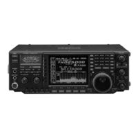
Icom IC-756PROII Service Manual (105 pages)
HF/50MHz ALL MODE TRANSCEIVER
Brand:
Icom
| Category:
Transceiver
| Size: 17.48 MB
Table of Contents
Table of Contents
3
Specifications
4
Inside Views
5
Circuit Description
7
Receiver Circuits
7
Transmitter Circuits
10
Pll Circuits
12
Antenna Tuner Circuits
14
Scope Circuit
15
Power Supply Circuits
15
Logic Circuits
16
Adjustment Procedures
21
Preparation before Servicing
21
Pll Adjustment
22
Transmitter Adjustment
25
Receiver Adjustment
28
Tuner Adjustment
32
Meter Adjustment
33
Parts List
35
Phone Board
38
Mode Board
38
MIC Board
38
Key Board
39
Pll Unit
39
Memory Board
51
Mechanical Parts
68
Semi-Conductor Information
72
Board Layouts
74
Pbt, Rit and MIC Boards
74
Display Board
75
Mode, Phone, Key and Ten-Key Boards
77
Rf-A Unit
79
Pll Unit
81
Main-A Unit
83
Dsp-A, Memory and Bpf Boards
85
Pa Unit
87
Filter Unit
89
Tuner Board
91
Ctrl Unit
93
Section 10 Voltage Diagrams
96
Section 9 Block Diagram
96
Front Unit
96
Dsp-A Board
97
Tuner, Memory Boards and Ctrl Unit
98
Main-A Unit (1)
99
Main-A Unit (2)
100
Pll Unit
101
Pa and Filter Units
102
Rf-A Unit and Bpf Board
103
Advertisement
Related Products
Icom IC-756
ICOM IC-756PRO III
ICOM IC-756PROIII
Icom IC-756PRO2
ICOM IC-751
Icom IC-751A
ICOM IC-746PRO
ICOM IC-7100
Icom IC-737
Icom IC-720A
ICOM Categories
Transceiver
Receiver
Repeater
Radio
Two-Way Radio
More ICOM Manuals
Login
Sign In
OR
Sign in with Facebook
Sign in with Google
Upload manual
Upload from disk
Upload from URL