Sign In
Upload
Manuals
Brands
hilscher Manuals
Gateway
NIOT-E-TIB100-GB-RE
hilscher NIOT-E-TIB100-GB-RE Manuals
Manuals and User Guides for hilscher NIOT-E-TIB100-GB-RE. We have
2
hilscher NIOT-E-TIB100-GB-RE manuals available for free PDF download: User Manual
hilscher NIOT-E-TIB100-GB-RE User Manual (263 pages)
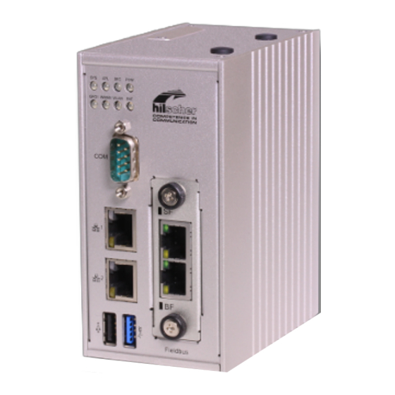
netIOT Edge Gateway
Brand:
hilscher
| Category:
Gateway
| Size: 5 MB
Table of Contents
User Manual Netiot Edge Gateway
2
Table of Contents
2
1 Introduction
6
About the User Manual
6
List of Revisions
6
Table 1: List of Revisions
6
2 Brief Description
7
Figure 1: Edge Gateway Communication Structure
7
3 Device Drawings
8
Positions of the Interfaces
8
Figure 2: Positions of the Interfaces of NIOT-E-TIB100-GB-RE
8
Table 2: Positions of the Interfaces of NIOT-E-TIB100-GB-RE
9
Dimensions
10
Figure 3: Dimensions
10
4 Connectors and Mounting
11
Mounting
11
LED Sticker
11
Power Supply
11
Figure 4: LED Label
11
Table 3: Power Supply Connector
11
LAN Connectors
12
Real-Time Ethernet Connectors
12
USB Connectors
12
Serial Interface
13
Table 4: Parameters of the Serial Interface
13
Table 5: RS-232 D-Sub
13
Table 6: RS-485 D-Sub
13
Wi-Fi
14
5 Leds
15
Positions of the Leds on the Gateway
15
Figure 5: NIOT-E-TIB100-GB-RE LED Positions
15
Gateway Status Leds
16
Leds of the LAN Interface
16
Table 7: Description of Gateway Status Leds
16
Table 8: Leds LAN Interface
16
Leds of the PROFINET IO Device Interface
17
Table 9: LED States for the PROFINET IO-Device Protocol
17
Table 10: LED State Definitions for the PROFINET IO-Device Protocol
17
Leds of the Ethernet/Ip Adapter Interface
18
Table 11: LED States for the Ethernet/Ip Adapter Protocol
18
Table 12: LED State Definitions for the Ethernet/Ip Adapter Protocol
19
6 Commissioning the Edge Gateway
20
Establishing the IP Address Communication
20
Figure 6: Default Settings of the Ethernet Network Connectors
20
Using the Web Browser to Establish a Connection with the Edge Gateway
22
Using the Host Name
22
Figure 7: Device Label: Hostname
22
Access to the Edge Gateway in the Windows Network Environment
23
Using the IP Address
23
Figure 8: Netiot Edge Gateway in the Windows Network
23
7 Edge Gateway Manager
24
Calling the Edge Gateway Manager
24
Figure 9: Edge Gateway Manager
24
Edge Gateway Manager Web Page
25
Table 13: Starting Applications with the Edge Gateway Manager
26
8 Control Panel
27
Opening the Control Panel
27
First Login
28
Figure 10: Edge Gateway Manager - Setting the Administrator Password
28
Secure Connection
29
Figure 11: Security Error Message of the Internet Explorer
30
Figure 12: Security Error Message of the Firefox Browser (1)
30
Figure 13: Security Error Message of the Firefox Browser (2)
30
Figure 14: Firefox Dialog Box: Adding Exceptional Safety Rule
31
Figure 15: Security Error Message of Google Chrome (1)
32
Figure 16: Security Error Message of Google Chrome (2)
32
Overview and Main Menu
33
Figure 17: Main Menu of the Control Panel
33
Table 14: Functional Overview of the Control Panel
33
System Information and System Time
35
Displaying System Information
35
Figure 18: Page Info Center
35
Table 15: Info Center: Area System Info
35
License Manager
36
Figure 19: License Manager with License for the Passive Mode of Operation
36
Table 16: Info Center: Area Monitoring
36
Table 17: Info Center: Area Temperature
36
Figure 20: License Information in Window Details
37
Figure 21: Message after the Transfer of the License File into the Edge Gateway
39
Displaying the System Log Files
40
Figure 22: Control Panel, Page System > Syslog
40
Table 18: Numeric Coding of Facility Value in Priority PRI
41
Table 19: Numeric Coding of Severity Value in Priority (PRI)
42
Table 20: Assignment of Parts of Message Line
43
Setting the System Time
44
Figure 23: Time Configuration Page
44
Table 21: Setting the System Time
44
Backup and Restore
47
Figure 24: Backup and Recovery
47
Figure 25: Warning Message
48
Figure 26: Backup in Progress
48
Figure 27: Backup and Recovery
49
Figure 28: Recovery Dialog
50
Figure 29: Security Query Prior to System Recovery from Internal Backup File
50
Figure 30: Backup and Recovery
51
Figure 31: Recovery Dialog (External Source)
52
Figure 32: Message Prior to Starting Recovery from External Backup
52
Figure 33: Backup and Restore When Backup File Is Present
53
Figure 34: Safety Query before Deletion of Local Backup
53
Rebooting the System
54
Figure 35: Backup and Restore
54
Figure 36: Reboot Safety Query
54
System Shutdown
55
Figure 37: Warning for Consequences of Shutdown
55
Packet Management
56
Managing Packets
56
Network
57
Configuring Ethernet Communication (LAN)
57
Figure 38: Default LAN Configuration
57
Table 22: Table LAN: Meaning of the Columns
58
Figure 39: LAN Configuration (Cifx0 Activated)
59
Configuring Wireless Communication (Wifi)
60
Figure 40: Wifi (Default Setting)
60
Figure 41: Wifi Modes of Operation
61
Table 23: Wifi Modes of Operation
61
Table 24: Wifi
61
Figure 42: Wifi Operating Mode: Access Point
62
Table 25: Parameters of the Operating Mode Access Point
62
Figure 43: Wifi Operating Mode: Client
63
Table 26: Parameters of the Operating Mode Client
64
Field
66
Table 27: Operating Mode Fieldbus Interface
66
Table 28: Operating Modes in the Passive Operating Mode
66
Hostname
67
Figure 44: Hostname
67
Services
68
Starting, Stopping and Configuring Services
68
Figure 45: List of Default Services
68
Table 29: Operating Statuses of the Services
68
Figure 46: OPC-UA Server for Edge Settings Within the Control Panel, Page Network>Field
69
Table 30: Parameters of the OPC UA Server for Edge
70
User Management
72
Managing User Roles
72
Figure 47: Page for Configuring Roles
72
Table 31: Access Rights Onto Resources
73
Table 32: Access Rights to Resources
73
Managing User Accounts
74
Figure 48: User Account Page
74
Security
75
Public Key Infrastructure
75
Figure 49: Public Key Infrastructure for Managing of Certificates
75
Figure 50: Certificate Type Selection List
76
Figure 51: Certificate Viewer
77
Help
78
Session
78
User Profile
78
Figure 52: Info Page
78
Figure 53: User Profile Page
78
Logout
79
Figure 54: Dialog "Edit User Account
79
9 Node-RED - the Wiring Editor
80
Modelling Iot Flows with Nodes
81
Figure 55: Comparison of the Physical and Logic View
81
Figure 56: Wiring the Nodes
81
Opening Node-RED
82
Figure 57: Node-RED Workspace
83
Graphical User Interface
84
Figure 58: Node-RED User Interface
84
Table 33: Node-RED User Interface
84
Figure 59: Node
85
Table 34: Node Elements
85
Working with Node-RED
86
Using Git Hub Repository to Store Flows (Projects)
88
Menu Deploy
89
Figure 60: Menu Deploy
89
Table 35: Commands of Menu Deploy
89
Dashboard
91
Table 36: Kinds of Widgets for Use in Dashboards
91
Table 37: Areas of the Dashboard Configuration
92
Figure 61: Dialog "Edit Dashboard Tab Node
94
Figure 62: Dialog "Edit Dashboard Tab Node
95
Figure 63: Dialog "Edit Dashboard Tab Node
96
Figure 64: Dialog "Edit Dashboard Tab Node
97
Figure 65: Dialog "Edit Link Node
99
Figure 66: Dialog "Edit Link Node
100
List of Nodes
101
Table 38: List of Standard Nodes
101
MQTT Input Node
104
Figure 67: MQTT Input Node
104
Figure 68: Dialog Box Edit MQTT in Node
104
Table 39: Parameter MQTT Input Node
104
Figure 69: Dialog Box MQTT Broker Config Node - Tab Connection
105
Table 40: Parameters in the Tab Connection
105
Figure 70: Dialog Box MQTT Broker Config Node - Tab Security
106
Table 41: Parameters in the Tab Security
106
Figure 71: Dialog Box MQTT Broker Config Node - Tab Birth Message
107
Table 42: Parameters in the Tab Birth Message
107
Figure 72: Dialog Box MQTT Broker Config Node - Tab will Message
108
Table 43: Parameters in the Tab will Message
108
MQTT Output Node
109
Figure 73: MQTT Output Node
109
Figure 74: Dialog Box Edit MQTT out Node
109
Table 44: Parameters of the Edit MQTT out Node
110
OPC UA Input Node
111
Figure 75: OPC UA Input Node
111
Figure 76: Dialog Box Edit OPC UA in Node - Tab Home
111
Table 45: Parameters of the Configuration Dialog OPC UA in Node
111
Figure 77: Dialog Box „Add New Opcua Client Config Node
112
Figure 78: Dialog Box „Edit Opcua in Node" - Tab Home
112
Figure 79: Dialog Box Edit OPC UA in Node - Tab Browse
113
Figure 80: Dialog Box Edit OPC UA in Node - Tab Mode - Polling
114
Figure 81: Options of the Selection List Payload
114
Figure 82: OPC UA in - Specific Payload
114
Table 46: Options of the Payload List
114
Figure 83: Options of the List Repeat
115
Table 47: Options of the List Repeat
115
Figure 84: Dialog Box Edit OPC UA in Node - Tab Mode - Subscribe
116
Table 48: Parameters in Subscription Settings and Monitored Items Settings
116
OPC UA Output Node
117
Figure 85: OPC UA Output Node
117
Figure 86: Dialog Box Edit OPC UA Output Node - Tab Home
117
Table 49: Parameters of the Configuration Dialog Edit OPC UA out Node
117
Figure 87: Dialog Box „Add New Opcua Client Config Node
118
Figure 88: Dialog Box Edit OPC UA out Node - Tab Browse
118
10 Examples for Node-RED
119
Example 1: Inject and Debug Node
119
Example 2: MQTT Input Node
121
Figure 89: MQTT Input Node
121
Example 3: MQTT Output Node
125
Figure 90: MQTT Output Node
125
Example 4: OPC UA Input Node
129
Figure 91: OPC UA Input Node
129
Example 5: OPC UA Output Node
135
Figure 92: OPC UA Output Node
135
Example 6: Fieldbus Input Node
142
Figure 93: Fieldbus Input Node
142
Figure 94: Message of the Fieldbus Input Node (Without Error)
148
Figure 95: Message of the Fieldbus Input Node (with Error)
149
Example 7: Fieldbus Output Node
150
Figure 96: Fieldbus Output Node
150
11 Configuring and Using the Fieldbus Node
158
Overview
158
Table 50: Standard Procedure
158
Table 51: Configuration Steps
159
Configuring the Fieldbus and Defining the Signals
160
Creating a New Fieldbus Configuration
160
Figure 97: Edit Dialog "Edit Fieldbus in Node
160
Figure 98: Dialog Box "Add New Fieldbus Interface Config Node
161
Figure 99: Dialog Box "Add New Fieldbus Interface Config Node
161
Figure 100: PROFINET Configuration
162
Figure 101: Available IO Items (Example in Figure: PROFINET)
163
Figure 102: IO Items (Example: PROFINET)
163
Figure 103: Dialog Box "Add New Fieldbus Interface Config Node
165
Figure 104: Error Message - Firmware Mismatch
166
Figure 105: Reconfigure Interface
166
Changing the Existing Fieldbus Configuration
167
Figure 106: Fieldbus Node
167
Figure 107: Dialog Edit Fieldbus in Node
167
Figure 108: Dialog Edit Fieldbus in Node
168
Figure 109: Dialog "Edit Fieldbus Interface Config Node
169
Figure 110: Button Open Fieldbus Configurator
169
Figure 111: Start Screen of the User Interface for Fieldbus Configuration of the Netiot Edge Gateway (the Example in the Figure Shows PROFINET)
170
Figure 112: Dialog Edit Fieldbus Interface Node
171
Figure 113: Error Message - Firmware Mismatch
172
Loading Firmware and Configuration
173
Figure 114: Message Box Firmware Already on Board
173
Figure 115: Warning: Consequences of Reconfiguration
173
12 Configuring PROFINET and Defining Signals
175
User Interface
175
Menu Commands
175
Figure 116: PROFINET User Interface
175
Table 52: PROFINET Configuration User Interface
175
Project - Save
176
GSDML Download
176
Printing the Configuration
176
Help - Contents
177
Help - Information
177
Configuration Tree
178
PROFINET Configuration
178
IO and Signal Configuration
178
Signal Definitions Overview
178
Download of the GSDML File
178
Figure 117: Note: Name of Station
178
Table 53: PROFINET Configuration Tree
178
Figure 118: List of the Possible Input and Output Modules
179
Figure 119: List of the Configured Input and Output Modules
179
Table 54: Contents of the Table "IO Items
179
Table 55: Controls of the Table "IO Items
180
Figure 120: Selected IO Item (Module) for Which You Define Signals
181
Figure 121: List of the Signal Names of an IO Item (Module)
181
Table 56: Contents of Table „IO Item
181
Table 57: Contents of the Table „Signals
182
Table 58: Controls of the Table „Signals
182
Table 59: Data Types for Signal Names
183
Table 69: Data Types for Signal Names
183
Figure 122: List of the Configured Input and Output Modules
184
Figure 123: List of the Send and Receive Signals
188
Table 60: Columns of the Table of the Send and Receive Signals
188
Help
189
13 Configuring Ethernet/Ip and Defining Signals
190
User Interface
190
Menu Commands
190
Figure 124: Ethernet/Ip User Interface
190
Table 61: Ethernet/Ip Configuration User Interface
190
Project - Save
191
EDS Download
191
Printing the Configuration
192
Help - Contents
192
Help - Information
192
Figure 125: IP Settings
193
Table 62: Ethernet/Ip Configuration Tree
193
IO and Signal Configuration
194
Table 63: Parameters for Setting the IP Addresses
194
Figure 126: List of the Possible Send and Receive Assemblies
195
Figure 127: List of the Configured Send and Receive Assemblies
195
Table 64: Contents of the Table „IO Items
195
Figure 128: Selected IO Item (Assembly) for Which You Define Signals
196
Table 65: Controls of the Table „IO Items
196
Table 66: Contents of the Table „IO Items
196
Figure 129: List of the Signal Names of an IO Item (Assembly)
197
Table 67: Contents of the Table „IO Items
197
Table 68: Controls of the Table „Signals
198
Figure 130: List of the Configured Send and Receive Assemblies
199
Signal Definitions Overview
203
Figure 131: List of the Send and Receive Signals
203
Table 70: Columns of the Table of the Send and Receive Signals
203
Download of the EDS File
204
Help
204
14 Edge Server
205
Function Principle
205
Communication with IT-Network and Mobile Devices
205
Figure 132: Edge Server Structure
206
Communication with the OT-Network
207
Access Rights to the REST API
207
Functions of the Edge Server
208
Table 71: Functions of the Edge Server
208
Internal Structure of the Edge Server
209
Figure 133: Edge Server Environment
209
Figure 134: Internal Structure of the Edge Server
209
Edge Server Control Center
210
Starting the Edge Server Control Center
210
Functions
210
Figure 135: Netiot Edge Server Icon Within the Edge Gateway Manager
210
Service List
211
Figure 136: Edge Server Control Center
211
Table 72: Symbols for the State of Operation in the Service List
211
Configuration of the Edge Server
213
The Configuration of IP Address Area
213
Figure 137: Server Configuration
213
Figure 138: Configuration of the Scan Settings
214
Figure 139: Correct Configuration of the Scan Settings
215
Selecting the Protocols to Scan for Field Devices
216
Figure 140: Scan Protocol Configuration
216
15 Isolated Application Execution with Docker
217
Docker, Image, and Container
217
Working with Docker Via the Web GUI
220
The Portainer.io Interface
220
Figure 141: Tile Docker in the Edge Gateway Manager
220
Figure 142: View of Portainer.io Dashboard
221
Figure 143: Container List (Portainer.io)
221
Example: Executing the Web Server NGINX as a Container
222
Table 73: Functions for Working with Containers
222
Figure 144: NGINX Example - Screen Page "Create Container
223
16 Public Key Infrastructure
224
Asymmetric Encryption
224
Figure 145: Process of Asymmetric Encryption
225
Certificates and Keys
226
Structure of a Certificate According to X.509
226
Table 74: Attributes Concerning the Issuer and Owner of the Certificate zum Zertifikats-Aussteller und Zertifikats-Inhaber
226
Hierarchy of Trust
227
File Formats for Certificate and Key Files
228
Use Cases
228
Use Case 1: Verification of the Authenticity of the Communication Partner (Server)
228
Figure 146: Use Case 1: Verification of the Authenticity of the Communication Partner (Server)
229
Use Case 2: Server Certificates for Edge Gateway Services
230
Figure 147: Use Case 2: Server Certificates for Edge Gateway Services
230
Table 75: Edge Gateway Services
231
Use Case 3: Client Certificates for Specific Servers
232
Working with Root Certificates
234
Display the List of Trustworthy Root Certificates
234
Upload a Trustworthy Certificate into the Edge Gateway
234
Download of Certificates from the Edge Gateway into a File
235
Removing Root Certificates/Cas that Are no Longer Considered as Trustworthy
235
Adding a New Trustworthy Certificate to the Trusted Certification Authority Store of the Edge Gateway
235
Working with Server Certificates for Inbound Connections
236
Working with Certificates for HTTP and OPC UA Server
236
Working with Key Files for HTTP and OPC UA Server
239
Working with Client Authentication Certificates for Outbound Connections
241
Working with Certificates for Client Authentication
241
Working with Key Files for Client Authentication
244
17 Technical Data
248
Technical Data NIOT-E-TIB100-GB-RE
248
Table 76: Techncal Data NIOT-E-TIB100-GB-RE
248
Technical Data PROFINET IO Device
250
Table 77: Technical Data PROFINET IO RT IRT Device Protocol
250
Technical Data Ethernet/Ip Adapter
251
Table 78: Technical Data Ethernet/Ip Adapter Protocol
251
18 Decommissioning, Dismounting and Disposal
252
Putting the Device out of Operation
252
Removing Device from Top hat Rail
252
Disposal of Waste Electronic Equipment
252
19 Appendix
253
Legal Notes
253
List of Figures
257
List of Tables
261
Contacts
263
Advertisement
hilscher NIOT-E-TIB100-GB-RE User Manual (145 pages)
Edge Gateway
Brand:
hilscher
| Category:
Gateway
| Size: 3 MB
Table of Contents
User Manual Edge Gateway Niot-E-Tib100-Gb-Re
2
Table of Contents
2
1 Introduction
4
About this Document
4
List of Revisions
4
Table 1: List of Revisions
4
2 Passive Process Data Acquisition with the Edge Gateway
5
Introduction
5
Comparison of Active and Passive Process Data Acquisition
5
The Edge Gateway as Test Access Point
6
Figure 1: Edge Gateway as Software-TAP
6
Figure 2: Setup with Hardware-TAP
7
Application Scenarios
8
Software-Based TAP
9
Figure 3: NIOT-E-TIB100-GB-RE - Passive Mode as Software TAP
9
Hardware-Based TAP (Netmirror)
11
Figure 4: NIOT-E-TIB100-GB-RE with Hardware TAP
11
Software-Based TAP Behind a Mirror Port
13
Figure 5: NIOT-E-TIB100-GB-RE - Passive Mode as Software TAP at the Morror Port of a Switch
13
Configuration for Passive Mode
14
Modes of Operation
14
Figure 6: Active Mode of Operation
14
Figure 7: Inactive Mode of Operation
15
Figure 8: Passive Operation Mode - Operational Mode
16
Figure 9: Example: Switching to Active Mode of Operation
17
Figure 10: Switching from Mode Configuration into the Mode Operational of the Passive Mode (Example: Swiching from Configuration to Operational)
18
Figure 11: Message Window When Switching to Operational Mode in Passive Mode of Operation
18
Table 2: Properties of the Three Modes of the Passive Mode
18
Configuration Parameters and Project Files
19
Figure 12: Button "Upload" (Part of the Configuration Page Within the Control Panel)
19
Figure 13: Button "Download" (Part of the Configuration Page Within the Control Panel)
20
Figure 14: Button "Remove" (Part of the Configuration Page Within the Control Panel)
20
Figure 15: OPC-UA Settings Within the Control Panel, Page Network>Field
21
Table 3: Input Fields for Communication Settings of the OPC UA Server for Edge
21
Table 4: Input Fields for Limitation Settings of the OPC UA Server for Edge
22
Figure 16: Safety Query When Storing the OPC UA Server Configuration
23
Table 5: Input Fields for Settings Concerning Connection Establishment of the OPC UA Server for Edge
23
3 Licensing
24
License Overview
24
Table 6: License Overview
24
Which Licenses Are Present in the Device
25
Figure 17: License Manager with License for the Passive Mode of Operation
25
Figure 18: License Information in Window Details
25
How to Order and Receive a License
26
How to Transfer a License into the Device
27
Figure 19: Message after the Transfer of the License File into the Edge Gateway
27
4 Use Cases
28
PROFINET (Automatic)
28
Figure 20: Application Example: Passive Process Data Acquisition with the NIOT-E- TIB100-GB-RE in PROFINET Networks
28
Step 1 - Start the Passive Fieldbus Configurator
29
Step 2 - Creating an Empty Project
30
Figure 21: Empty GUI of the Passive Fieldbus Configurator
30
Step 3 - Adjust Basic Settings of the Passive Fieldbus Configurator
31
Figure 22: Side Menu
31
Figure 23: Main Menu - Register Card "Views
31
Figure 24: Main Menu - Register Card "Device Assignment
32
Figure 25: Error Message "The Connection to the Device was Not Possible
33
Figure 26: Selection List Network Speed
33
Table 7: Settings for Network Speed
33
Step 4 - Loading the GSDML Files
34
Figure 27: Context Menu at Network Level
34
Figure 28: Network Wizard
34
Figure 29: Selection List Network Protocol
34
Figure 30: Import of Device Descriptions
35
Figure 31: Imported Device Description Within the Item List of the Passive Fieldbus Configurator (Example)
35
Step 5 - Acquiring the Start-Up of PROFINET Communication
36
Step 6 - Signal Configuration
37
Figure 32: Window "Signal Configuration" of the Passive Fieldbus Configurator
37
Step7 - Check Signals in the Live-Data View
38
Step 8 - Storing the Generated Configuration File (PROFINET)
38
PROFINET (Manual)
39
Figure 33: Application Example: Passive Process Data Acquisition with the NIOT-E- TIB100-GB-RE in PROFINET Networks
39
Step 1 - Start the Passive Fieldbus Configurator
40
Step 2 - Creating an Empty Project
40
Figure 34: Empty GUI of the Passive Fieldbus Configurator
40
Step 3 - Adjust Basic Settings of the Passive Fieldbus Configurator
41
Figure 35: Side Menu
41
Figure 36: Main Menu - Register Card "Views
41
Figure 37: Main Menu - Register Card "Device Assignment
41
Figure 38: Selection List Network Speed
42
Table 8: Settings for Network Speed
42
Step 4 - Loading the GSDML Files
43
Figure 39: Context Menu at Network Level
43
Figure 40: Network Wizard
43
Figure 41: Selection List Network Protocol
43
Figure 42: Import of Device Descriptions
44
Figure 43: Imported Device Description Within the Item List of the Passive Fieldbus Configurator (Example)
44
Step 5 - Manual Configuration of PROFINET IO-Controller and -Devices
45
Figure 44: Context Menu Entry "Add Controller
45
Figure 45: Controller Assistant
45
Figure 46: Context Menu Entry "Add Device
46
Figure 47: Device Assistant
46
Figure 48: Context Menu Entry "Add Module
47
Figure 49: Module Assistant
48
Figure 50: Context Menu Entry "Add Submodule
49
Figure 51: First Page of Dialog "Submodule Assistant
49
Figure 52: Second Page of Dialog "Submodule Assistant
50
Figure 53: Context Menu Entry "Add Variable
52
Figure 54: Variable Wizard - First Page (Parameter)
52
Figure 55: Dialog Variable Wizard - Third Page (Normalization/Downsampling)
54
Figure 56: Edit Custom Value Filter - Downsampling-Type and -Rate
55
Step 6 - Signal Configuration
56
Figure 57: Window "Signal Configuration" of the Passive Fieldbus Configurator
56
Step 7 - Check Signals in the Live-Data View
57
Step 8 - Storing the Generated Configuration File (PROFINET)
57
Ethercat (Automatic)
58
Figure 58: Wiring Diagram for Passive Process Data Acquisition with the Edge Gateway NIOT-E-TIB100-GB-RE in Ethercat Networks
58
Step 1 - Program Start
59
Step 2 - Creating an Empty Project
59
Step 3 - Adjust Basic Settings of the Passive Fieldbus Configurator
60
Figure 59: Side Menu
60
Figure 60: Main Menu - Register Card "Views
60
Figure 61: Main Menu - Register Card "Device Assignment
61
Figure 62: Error Message "The Connection to the Device was Not Possible
62
Figure 63: Selection List Network Speed
62
Table 9: Settings for Network Speed
62
Step 4 - Upload the ENI File
63
Figure 64: Context Menu at Network Level
63
Figure 65: First Page of the Network Wizard for Ethercat
63
Figure 66: Selection of Network Protocol
63
Figure 67: Second Page of the Network Wizard for Ethercat
64
Table 10: Options for the Data Direction Within an Ethercat Network
64
Figure 68: Ethercat Import
65
Step 5 - Signal Configuration
66
Figure 69: Signal Configuration - During Drag&Drop
66
Step 6 - Check Signals in the Live-Data View
67
Figure 70: Adding Signals to the Live Data Window
67
Step 7 - Storing the Generated Configuration File (Ethercat)
68
Ethercat (Manual)
69
Figure 71: Wiring Diagram for Passive Process Data Acquisition with the Edge Gateway NIOT-E-TIB100-GB-RE in Ethercat Networks
69
Step 1 - Start the Passive Fieldbus Configurator
70
Step 2 - Creating an Empty Project
70
Edge Gateway NIOT-E-TIB100-GB-RE | Passive Operating Mode © Hilscher
70
Step 3 - Adjust Basic Settings of the Passive Fieldbus Configurator
71
Figure 72: Side Menu
71
Figure 73: Main Menu - Register Card "Views
71
Figure 74: Main Menu - Register Card "Device Assignment
71
Figure 75: Selection List Network Speed
72
Table 11: Settings for Network Speed
72
Step 4 - Configuration of the Process Fieldbus Configurators for Ethercat
73
Figure 76: Context Menu at Network Level
73
Figure 77: First Page of the Network Wizard for Ethercat
73
Figure 78: Selection of Network Protocol
73
Figure 79: Second Page of the Network Wizard for Ethercat
74
Table 12: Options for the Data Direction Within an Ethercat Network
74
Step 5 - Manual Configuration of the Ethercat Network
75
Figure 80: Context Menu for Ethercat Master
75
Figure 81: Dialog „Add Slave - First Page (Name)
76
Figure 82: Dialog Add Slave - Second Page"(Parameter)
76
Table 13: Coding of Parameter "Physics
77
Figure 83: Context Menu for Ethercat Master
78
Figure 84: Context Menu for Ethercat Slave
78
Figure 85: Variable Wizard - First Page
79
Table 14: Possible Selections Depending on Mode of Operation
80
Figure 86: Dialog Variable Wizard - Second Page
81
Figure 87: Dialog Variable Wizard - Third Page (Normalization/Downsampling)
85
Figure 88: Edit Custom Value Filter - Downsampling-Type and -Rate
86
Step 6 - Signal Configuration
87
Figure 89: Signal Configuration - During Drag&Drop
87
Step 7 - Check Signals in the Live-Data View
89
Figure 90: Adding Signals to the Live Data Window
89
Step 8 - Storing the Generated Configuration File (Ethercat)
90
Custom Value Filters
91
Table 15: Criteria for Frame Selection
91
Step 1 - Start the Passive Fieldbus Configurator
92
Step 2 - Creating an Empty Project
92
Step 3 - Adjust Basic Settings of the Passive Fieldbus Configurator
93
Figure 91: Side Menu
93
Figure 92: Main Menu - Register Card "Views
93
Figure 93: Main Menu - Register Card "Device Assignment
94
Step 4 - Define Filter Conditions for Custom-Value Filters
95
Figure 94: Error Message "The Connection to the Device was Not Possible
95
Figure 95: Assignment of the Four Filter Criteria to the Wireshark Trace
96
Figure 96: Specify Filter Name
97
Figure 97: Custom-Value Filters - Selection of Logical Function
97
Figure 98: Custom Value Filters
98
Figure 99: Custom Value Filters - Selection of Ethertype for Recognition of Powerlink Frames
98
Figure 100: Custom Value Filters
99
Figure 101: Custom Value Filters - First Filter Condition Complete (Including Wireshark Trace)
99
Figure 102: Specifying the Second Filter Criterion - Entering the Filter Condition
100
Figure 103: Specifying the Second Filter Criterion - Selection of User-Defined Uint8
100
Figure 104: Specifying the Second Filter Criterion -Afdter Selection of User-Defined Uint8
101
Figure 105: Specifying the Second Filter Criterion - Input of the Value of Ethernet Frame, Byte
101
Figure 106: Specifying the Second Filter Criterion - Input of the Offset
102
Figure 107: Specifying the Second Filter Criterion
102
Figure 108: Specifying the Third Filter Criterion - Entering the Third Filter Condition
103
Figure 109: Specifying the Second Filter Criterion - Selection of User-Defined Uint8
103
Figure 110: Specifying the Third Filter Criterion -After Selection of User-Defined Uint8
104
Figure 111: Specifying the Third Filter Criterion - Input of the Value of Ethernet Frame, Byte
104
Figure 112: Specifying the Third Filter Criterion - Input of the Offset
105
Figure 113: Specifying the Third Filter Criterion (with Wireshark Trace)
105
Figure 114: Specifying the Fourth Filter Criterion - Entering the Filter Condition
106
Figure 115: Specifying the Fourth Filter Criterion - Selection of User-Defined Uint8
106
Figure 116: Specifying the Fourth Filter Criterion - after Selection of User-Defined Uint8
107
Figure 117: Specifying the Flurth Filter Criterion - (with Wireshark Trace)
108
Figure 118: Custom-Value Filters - Specifications for Extracting the Values out of the
109
Table 16: Custom-Value Filters - Approaches to Extraction
109
Figure 119: Custom-Value Filters - Specification for Normalization of Acquired Data
110
Table 17: Custom-Value Filters - Parameters for Extraction and Their Meaning
110
Step 5 - Signal Configuration
112
Figure 120: Window "Signal Configuration" of the Passive Fieldbus Configurator
112
Step 6 - Check Signals in the Live-Data View
113
Step 7 - Storing the Generated Configuration File
113
Uploading the Project File to the Edge Gateway
114
Figure 121: Passive Mode of Operation - Config Mode
114
Figure 122: OPC UA Configuration (Figure Only Shows a Part)
115
Figure 123: Button "Upload" in the Signal Configuration Area of the Configuration Page in the Control Panel
115
Figure 124: Switching to Operational Mode in Passive Mode of Operation
116
Figure 125: Dialog Window Displayed When Switching into the Operational Mode of the Passive Mode
116
Error Handling
117
Figure 126: Error Message "Parsing Error in
118
Figure 127: Error Message "Failed to Load ENI File
118
Figure 128: GSDML File Already Exists
119
Figure 129: Overwriting of Existing Elements
119
Figure 130: a Module with same Slot Number Already Exists
120
Figure 131: a Submodule with same Subslot Number Already Exists
120
Figure 132: Wireshark Example for Codesys ENI-Import
121
5 Further Processing of the Process Data
122
Overview
122
OPC UA Client Reads Process Data from Edge Gateway
122
Table 18: Possibilities for Further Processing of the Process Data
122
Selecting Signals for OPC UA
123
Figure 133: Selecting Signals for OPC UA
123
Example: Access to the Edge Gateway over OPC UA Using the Client UA Expert
124
Figure 134: Intro Screen of OPC UA Client UA Expert
124
Figure 135: Context Menu of the UA Expert
125
Figure 136: Dialog Add Server in UA Expert
125
Figure 137: Dialog Box Enter Url in UA Expert
125
Node-RED Transfers Process Data into the Cloud
127
Selecting Signals for Node-RED
127
Figure 138: Selecting Signals for Node-RED
127
The Input Node "Passivefieldbus
128
Figure 139: Edit Passive Fieldbus Node
128
Table 19: Parameters for the Configuration of Node Passivefieldbus
128
Figure 140: Edit Window for Specifying the Parameters
130
Structure of the Data Delivered by the Input Node
131
Table 20: Structure of the Process Variables (Elements of JSON Array)
132
Table 21: Structure of the Elements of the Value List
132
Display of Data Processing Status
133
Adjusting the Timing in Order to Prevent Data Loss
133
Figure 141: Example: Timing Diagram
133
Table 22: Status of Data Processing in Node-RED
133
Using a Docker Container to Access to the Raw Data
134
6 Performance Considerations
135
Only Use a Single Passivefieldbus Node
135
7 Appendix
136
Legal Notes
136
List of Figures
140
List of Tables
144
Contacts
145
Advertisement
Related Products
hilscher NIOT-E-TIJCX-GB-RE
hilscher netPI NOIT-E-NPI3-51-EN-RE
hilscher NIOT-E-TPI51-EN-RE
hilscher netNode
hilscher netTAP NT 50 Series
hilscher netFIELD NIOT-ETPI51-EN-RE/NFLD
hilscher netFIELD
hilscher NFX8M-D2-N32-010
hilscher netBRICK NB 100
hilscher NIOT-E-NPIX-RS485
hilscher Categories
Gateway
Computer Hardware
Motherboard
Network Hardware
PCI Card
More hilscher Manuals
Login
Sign In
OR
Sign in with Facebook
Sign in with Google
Upload manual
Upload from disk
Upload from URL