Sign In
Upload
Manuals
Brands
Haier Manuals
Air Conditioner
H-MRV AF122FCBHA
Haier H-MRV AF122FCBHA Manuals
Manuals and User Guides for Haier H-MRV AF122FCBHA. We have
3
Haier H-MRV AF122FCBHA manuals available for free PDF download: Service Manual, Operation Manual
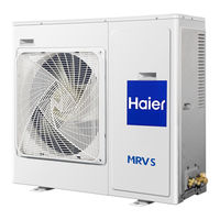
Haier H-MRV AF122FCBHA Service Manual (201 pages)
H-MRV Series
Brand:
Haier
| Category:
Air Conditioner
| Size: 14.62 MB
Table of Contents
3
General Information
3
Model Code Description
3
H-MRV Series Line up
5
Product Features
8
Specifications
11
Specifications for Indoor Units
19
Dimensions
23
Parts Name
23
Indoor Units
26
Controller Functions
32
About Health Function
34
Infrared Controller
36
Cool, Heat and Dry Operation
36
Loading the Battery
36
Replacing the Battery Compartment Lid
36
Confirmation Indicator
37
Timer On-Off Function
38
Health & Fresh Air Operation
38
Health Operation
38
About Health Operation
38
About Fresh Air Operation
39
Series Remote Controller Units
41
Refrigerant Circuit
43
Installation Instruction
43
Outdoor Installation
51
Piping Dimension Chart
51
Y-Shape Manifold Pipe
52
Refrigerant Pipes between Manifold Pipes
54
Instructions for the Electrical Expansion Valve Boxes
54
Installation Position
54
Installation Place
57
Piping Length and Drop between Units
58
Combination Example
68
Install a Suspending Bolt
68
Installation of Outdoor Unit
68
Installation of Water Drainage Pipe
69
Installation of Ornament Panel
69
Cautions for the Water Drainage Lifting Pipe
70
Cautions for Operation the Panel
71
Convertible Indoor Unit
71
Standard Accessories
71
Remove the Intake Grill
71
Drilling for Piping
72
Installing Drain Hose
72
Under Ceiling Type
73
Installing Brackets
73
Installing Indoor Unit
74
Install the Drain Hose
74
Gas Leakage Inspection
74
How to Connect Wiring to the Terminals
75
For Strand Wiring
75
Electrical Wiring
76
Indoor Unit Side
77
Test Running
77
Check Items
77
Customer Guidance
78
Mount the Cover Plate
78
Mount the Intake Grill
80
Installation of Indoor Unit Duct
80
Installation of Air Sending Duct
80
Installation of Air Return Duct
81
Thermal Insulation of Duct
81
Installing the Suspension Screw
81
Hanging of the Indoor Unit
82
Requirements
82
Pipe and Insulation Material
82
Hose
83
Connection of Refrigerant Pipe
83
Vacuum Pumping
83
Insulation Treatment
84
Selection of Installation Place
84
Fixing the Unit
85
Schematic Diagram for Unit Connection
85
Connection Pipe Dimensions
85
Cautions for Pipe Connection
86
Electric Wiring
86
Arrangement Drain Hose
86
Wiring of Indoor Unit
86
Wiring Diagram
87
Power Supply Requirements
87
Piping Cutting and Flaring
88
Installation for AS07~18
89
Precaution
89
Self-Contained Accessories
89
Electrical Requirements
90
Accessories
90
Method for Cutting and Expanding Pipes
91
When the Mounting Plate Is Firstly Fixed
91
Making a Hole on the Wall and Fitting the Piping Hole Cover
91
Drawing of Pipe
92
Other Direction Piping
92
Fixing the Indoor Unit Body
92
How to Connect Wiring to the Terminals
93
Check the Layout of the Drain Pipe and Connection Wires
93
Trial Operation
93
Winding up with Protective Plastic Tape
94
Display of Whole Unit
94
Fixing of the Unit
94
Position of the Wall Hole
94
Making a Hole
95
Connecting Method
95
Piping Connection of Indoor Unit
95
Arrangement of Piping and Drainage Pipe
96
Arrangement of Drain Hose
97
Wiring of Outdoor Unit
98
Electric Control Functions
98
Protection at Startup
98
Soft Startup
98
Outdoor Fan Motor Control
99
Heat Exchanger Temperature Sensor te
99
Oil Return Operation in Cooling
99
Refrigerant Return Control in Heating
99
Remains Heating Operation
100
Electric Control Functions of AU48NFIBIA
100
Capacity Control of Compressor
100
Startup Control of Compressor
102
Defrost Control
102
Defrosting Beginning Conditions
102
Defrosting Finish Conditions
102
Protection During Defrost
103
Oil Return Operation
103
Compressor Overheat Protection
103
Oil Return Operation in Heating
103
Input Protection Signal
104
Jumping Frequency Point Design
104
Time Shorting Function
105
Indoor Unit Electric Control Functions
105
Cooling Mode
105
Characteristic of Electronic Expansion Valve (EEV)
105
Fan Motor Control
106
Anti-Freezed Operation Start Condition
106
Anti-Freezed Operation Stop Condition
106
Dry Operation Mode
106
Fan Speed Control
107
Temperature Compensation
107
Anti-Cold Air Operation
107
Correction of Overheat Value
107
Correction of Discharging Temperature
108
Emergent Switch
108
Perform 2 Seconds Later
108
Fresh Air Function
108
Indoor Unit Number Setting
109
Indoor Communication Abnormal
109
Time-Shorting Function
109
Auto Restart Function
109
Abnormal Mode
110
Electrical Wiring Diagram
110
Outdoor Wiring Diagram
111
Outdoor Wiring Diagram for Au48Nfibia
111
Power Supply
111
Control Board
112
Outdoor Wiring Diagram for Au482Fibha
113
Ab092/142/182Fcbha Indoor Wiring Diagram
113
Indoor Pcb
114
Ac142/182Fcbha Indoor Wiring Diagram
115
Indoor Unit Wiring Diagram AE07/09/12/14/18/242FCBKA
115
Indoor Control Board
116
Electronic Expansion Valve Wiring Diagram
120
Electric Data
120
PCB Circuit Diagram and Main Electric Part Specs
120
AU242FHBHA PCB Circuit Diagram
121
AU242FHBHA PCB Top Layer Printed Diagram
122
AU242FHBHA PCB Bottom Layer Printed Diagram
123
Main Parts of AU242FHBHA PCB
125
AU242FHBHA PCB Ports Name and Functions
126
AU482FIBHA High Voltage PCB Circuit Diagram
127
AU482FIBHA High Voltage PCB Printed Diagram
130
AU482FIBHA Low Voltage PCB Circuit Diagram
131
AU482FIBHA Low Voltage PCB Printed Diagram
132
Main Parts of AU482FIBHA Low Voltage PCB
134
AU482FIBHA PCB Ports Name and Functions
136
Combination Control with Outdoor Switches
139
AU48NFIBIA Power Module Board Circuit Diagram
140
AU48NFIBIA Low Voltage Board Circuit Diagram
141
AU48NFIBIA Filter Board Circuit Diagram
142
AU48NFIBIA Driving Board Circuit Diagram
143
AU48NFIBIA Power Module Board Parts List
145
AU48NFIBIA Filter Board Parts List
148
AU48NFIBIA PCB Ports Name and Functions
149
Control Board 0010451530
150
Power Board 0010451531
150
Filter Board 0010451536
151
AB092~182FCBHA PCB Circuit Diagram
152
AB092~182FCBHA PCB Printed Diagram
153
Main Parts of AB092,142,182FCBHA PCB
155
AE**FCBKA PCB Circuit Diagram
156
AE**FCBKA PCB Printed Diagram
157
Main Parts of AE072~242FCBKA PCB
160
Sensor Characteristic
163
Failure Code and Troubleshooting
163
AU242FHBHA Fault Code List
164
AU242FHBHA Troubleshooting
164
Communication Failure between Indoor and Outdoor Units
165
Sensor Failure
165
EEPROM Failure
165
Over Current Protection
166
IPM Power Module Protection
167
Discharging Temperature Protection
168
High Pressure Overhigh Protection
169
AU482FIBHA Fault Code List
171
AU482FIBHA Troubleshooting
178
AU48NFIBIA Malfunction Code
179
AU48NFIBIA Troubleshooting
179
Communication Failure
181
Over Current Protection: Outdoor LED302 Flashes 6 Times
186
Testing Board for AU48NFIBIA
187
Fault Code List for H-MRV Indoor Unit
188
H-MRV Indoor Unit Troubleshooting
190
Replace the Fan
193
Performance Curves
194
Calculation Method
195
Noise Curves
Advertisement
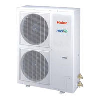
Haier H-MRV AF122FCBHA Service Manual (174 pages)
Home MRV
Brand:
Haier
| Category:
Air Conditioner
| Size: 12.09 MB
Table of Contents
1
Service Manual
2
Table of Contents
3
1 Description of Products & Features
3
Combination of Indoor and Outdoor
3
Indoor Unit
3
Nomenclature
3
Outdoor Unit
4
Models of Indoor and Outdoor Units
7
Character of Products
8
Cooling and Heating Capacity Curves
11
2 Specifications
25
Airflow Direction
25
3 Mechanical Data
25
Temperature Setting
25
Time Setting
26
Remote Controller
27
Clock Set
28
Fan Speed
29
Timer Off
30
Refrigerant Diagram
35
4 Electrical Data
35
Wiring Diagram
39
Control Board
43
Indoor Pcb
47
Circuit Diagram
62
Resistance-Temperature Character
63
6 Electrical Control Functions
63
5 Noise Level Chart
63
Indoor Unit No. Setting Method
64
Reset Button
66
Flow Chart for Operation
71
Defrost Operation Flow Chart
73
7 Diagnostic Information (Trouble Shooting)
73
Fault Codes
77
Troubleshooting
79
Example of Repair
80
8 Installation Instructions
80
Piping Dimensions Chart
80
Y-Shape Manifold Pipe
85
Piping Length and Drop Between the Units
86
Combination Examples
89
Installation Dimensions
95
The Order of Installation Work
95
Attentive Matters of Safety
97
Special Work and Main Points in Installation
98
Test of Airtight Quality
100
Charging of Refrigerant
101
Refrigerant
102
Electric Wiring
107
Checks After the Installation
108
Standard Accessories
110
Wiring of Indoor Unit
112
Installation Tools
116
Installation of Indoor Unit
119
Installation of Remote Controller
120
Drain Pipe
121
Installation Procedure
133
Refrigerant Piping
135
9 Exploded Views & Part Lists
139
Parts List
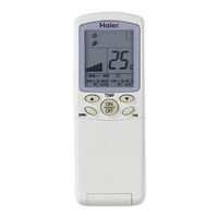
Haier H-MRV AF122FCBHA Operation Manual (4 pages)
Haier YR-H71: User Manual
Brand:
Haier
| Category:
Remote Control
| Size: 1.67 MB
Advertisement
Share and save
Advertisement
Related Products
Haier AF122XCEAA
Haier AF122XCBAA
Haier AF122XCERA
Haier AF122MAERA
Haier Super Match AF12AS1ERA
Haier Super Match AF12AB1HRA
Haier AF142XCEAA
Haier AF142XCBAA
Haier AF182AFMAB
Haier AF182MAERA
Haier Categories
Air Conditioner
Washer
Refrigerator
TV
Freezer
More Haier Manuals
Login
Sign In
OR
Sign in with Facebook
Sign in with Google
Upload manual
Upload from disk
Upload from URL