Sign In
Upload
Manuals
Brands
Fujitsu Manuals
Storage
Hard Drive
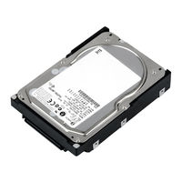
Fujitsu Hard Drive Manuals
Manuals and User Guides for Fujitsu Hard Drive. We have
1
Fujitsu Hard Drive manual available for free PDF download: Scsi Logical Interface Specifications
Fujitsu Hard Drive Scsi Logical Interface Specifications (310 pages)
Specifications
Brand:
Fujitsu
| Category:
Storage
| Size: 2.09 MB
Table of Contents
Revision History
3
Acronyms and Abbreviations
6
Conventions Used in this Manual
7
Table of Contents
11
CHAPTER 1 Command Processing
19
1.1 Command Format
19
Figure 1.1 6-Byte CDB Basic Format
19
Figure 1.2 10-Byte CDB Basic Format
20
Figure 1.3 12-Byte CDB Basic Format
20
Status
24
Figure 1.4 Status
24
Outline of Command Processing
26
Single Commands
26
Command Link
27
Table 1.1 Responses to Link Specification Commands
28
Disconnect/Reconnect Processing
29
Table 1.2 Types of Command and Disconnect Processing
30
Synchronous Mode Data Transfer/Wide Mode Data Transfer
33
Command Queuing Function
34
Untagged Queuing
34
Tagged Queuing
36
1.5 UNIT ATTENTION Condition
37
Generation of the UNIT ATTENTION Condition
37
Response and Release Condition at UNIT ATTENTION Condition Hold State
38
UNIT ATTENTION Condition Multiple Hold
40
Sense Data Hold State
40
Sense Data Hold Condition
40
Response and Release Conditions at Sense Data Hold State
40
Command Processing Exceptions
41
Overlapping Commands
41
Illegal LUN Specification
42
Reserved Operation Code
42
Command Processing in the Not Ready State
42
Table 1.3 Sense Data in Not Ready State
43
Error Recovery Processing
44
Reset Processing
46
Fatal Hardware Errors
47
Table 1.6 Reset Processing During Write
47
Data Block Addressing
48
Definition of Data Space
48
Figure 1.5 Data Space Configuration
49
Logical Block Addressing
50
CHAPTER 2 Data Buffer Management
51
Data Buffer
51
Data Buffer Configuration and Basic Operation
51
Figure 2.1 Data Buffer Configuration (in the Case of 8 Cache Segments)
52
Figure 2.2 Example of Data Buffer Operation During Read
53
Figure 2.3 Example of Data Buffer Operation During Write
54
Operation Mode Setting
55
2.2 Look-Ahead Cache Feature
57
Caching Parameters
59
Figure 2.5 Cache Control Parameters
59
Look-Ahead Operation, Look-Ahead Volume
60
Write Cache
61
CHAPTER 3 Command Specifications
63
Control/Sense Commands
63
Test Unit Ready (00)
63
Inquiry (12)
64
Figure 3.1 Standard INQUIRY Data
66
Figure 3.2 Command Support Data
71
Figure 3.3 VPD Information: VPD Identifier List
73
Figure 3.4 VPD Information: Device Serial no
73
Figure 3.5 VPD Information: Operation Mode
74
Read Capacity (25)
75
Change Definition (40)
76
Figure 3.6 READ CAPACITY Data
76
Mode Select (15)
81
Figure 3.8 MODE SELECT Parameter Structure
83
Figure 3.9 MODE SELECT Command (Group 0) Parameter Configuration
85
Mode Select Extended (55)
89
Figure 3.10 MODE SELECT EXTENDED Command (Group 2) Parameter Configuration
91
Mode Sense (1A)
92
Table 3.1 MODE SENSE Data Type Specifications
95
Figure 3.11 MODE SENSE Command (Group 0) Parameter Configuration
96
Mode Sense Extended (5A)
100
Figure 3.12 MODE SENSE EXTENDED Command (Group 2) Parameter Configuration
101
Rezero Unit (01)
103
Start/Stop Unit (1B)
103
Reserve (16)
105
Reserve Extended (56)
108
Release (17)
109
Release Extended (57)
110
Request Sense (03)
110
Log Select (4C)
112
Figure 3.13 LOG, SELECT Command: Parameter List
113
Figure 3.14 LOG SELECT Command: Log Parameter
114
Log Sense (4D)
116
Persistent Reserve in (5E)
117
3.1.18.1 PERSISTENT RESERVE in Service Actions
118
Read Keys
118
3.1.18.1.2 Read Reservations
119
3.1.18.2 PERSISTENT RESERVE in Parameter Data for READ KEYS
119
Figure 3.15 PERSISTENT RESERVE in Command: Parameter Data (READ KEYS)
119
3.1.18.3 PERSISTENT RESERVE in Parameter Data for READ RESERVATIONS
120
Figure 3.16 PERSISTENT RESERVE in Command: Parameter Data (READ RESERVATIONS)
120
3.1.18.3.1 Persistent Reservation Scope
121
Figure 3.17 PERSISTENT RESERVE in Reservation Descriptor
121
3.1.18.3.2 Persistent Reservations Type
122
Table 3.2 Persistent Reservation Type Codes
123
Persistent Reserve out (5F)
124
3.1.19.1 PERSISTENT RESERVE out Service Actions
125
3.1.19.2 PERSISTENT RESERVE out Parameter List
126
Figure 3.18 PERSISTENT RESERVE out Command: Parameter List
126
Table 3.3 PERSISTENT RESERVE out Command Service Action Codes
126
Report Luns (A0)
128
Figure 3.19 REPORT LUNS Command: Parameter List
129
Report Device Identifier (A3)
130
Figure 3.20 REPORT DEVICE IDENTIFIER: Parameter List
130
Set Device Identifier (A4)
131
Figure 3.21 SET DEVICE IDENTIFER: Parameter List
132
3.2 Data Access Commands
133
Read (08)
133
Read Extended (28)
134
Write (0A)
135
Write Extended (2A)
136
Write and Verify (2E)
137
Verify (2F)
138
Seek (0B)
139
Seek Extended (2B)
139
SET LIMITS (33) (Not Supported)
140
Figure 3.22 SET LIMITS Command: Specifying the Range Where Access Is Permitted
141
Synchronize Cache (35)
142
Format Commands
143
Format Unit (04)
143
Figure 3.23 FORMAT UNIT Command Parameter List Configuration
146
Figure 3.24 Defect Descriptor: Byte Distance from Index Format
149
Figure 3.25 Defect Descriptor: Physical Sector Address Format
150
Table 3.5 FORMAT UNIT Command Defect Processing
151
Reassign Blocks (07)
153
Figure 3.26 REASSIGN BLOCK Command: Defect Data List Configuration
154
Read Defect Data (37)
156
Figure 3.27 READ DEFECT DATA Command (37): Defect Data Configuration
157
Read Defect Data (B7)
160
Maintenance, Diagnostic Commands
161
Send Diagnostic (1D)
161
Figure 3.28 READ DEFECT DATA Command (B7): Defect Data Configuration
161
Table 3.6 Error Recovery Control Flags During the Self-Diagnosis Test
163
Figure 3.29 SEND DIAGNOSTIC Command: Parameter List Configuration
164
Figure 3.30 SEND DIAGNOSTIC Parameters: Page Code List
165
Figure 3.31 SEND DIAGNOSTIC Parameters: Logical/Physical Address Conversion
166
Receive Diagnostic Results (1C)
168
Figure 3.32 RECEIVE DIAGNOSTIC RESULTS Command: Response Data Configuration
169
Figure 3.33 RECEIVE DIAGNOSTIC RESULTS Response Data: Page Code List
170
Figure 3.34 RECEIVE DIAGNOSTIC RESULTS Response Data: Logical/Physical Address Conversion
170
Write Buffer (3B)
172
Figure 3.35 WRITE BUFFER Command: Buffer Data (Mode = 000, 001)
173
Read Buffer (3C)
177
Figure 3.36 READ BUFFER Command: Buffer Data (Mode = 0000, 0001)
178
Figure 3.37 READ BUFFER Command: Buffer Descriptor
179
Figure 3.38 READ BUFFER Command: Echo Buffer Descriptor
180
Read Long (3E)
181
Write Long (3F)
182
Write same (41)
183
CHAPTER 4 Parameter Data Formats
185
Mode Parameters
185
Read/Write Error Recovery Parameters (Page Code = 1)
185
Table 4.1 Combinations of Error Recovery Flags
191
Disconnect/Reconnect Parameters (Page Code = 2)
194
Format Parameter (Page Code = 3)
198
Figure 4.4 MODE SELECT Parameters: each Parameters of Pages 3, 4, and C in Detail
201
Drive Parameter (Page Code = 4)
202
Verify Error Recovery Parameters (Page Code = 7)
203
Caching Parameters (Page Code = 8)
205
Control Mode Parameters (Page Code = 0A)
211
Notch Parameter (Page Code = 0C)
215
Port Control Parameter (Page Code = 19)
217
Informational Exceptions Control Page (Page Code = 1C)
227
Table 4.2 MRIE (Methods of Reporting Informational Exception Conditions)
229
Background Control Mode Parameter (Page Code = 1C/Subpage = 01)
231
Additional Error Recovery Parameters (Page Code = 21)
232
Log Parameters
233
Supprot Log Page (X'00')
233
Buffer Overrun / Underrun Page (X'01')
234
Write Error Count Page (X'02')
235
Write Errors Recovered Without Delays (Page 02, Code 0000)
235
Total Posted Write Errors (Page 02, Code 0002)
236
Write Errors Recovered with Possible Delays (Page 02, Code 0001)
236
Total Posted Recoverable Write Errors (Page 02, Code 0003)
237
Total Write Bytes Processed (Page 02, Code 0005)
237
Total Posted Unrecoverable Write Errors (Page 02, Code 0006)
238
Read Error Count Page (X'03')
238
Read Errors Recovered with Possible Delays (Page 03, Code 0001)
239
Read Errors Recovered Without Delays (Page 03, Code 0000)
239
Total Posted Read Errors (Page 03, Code 0002)
240
Total Posted Recoverable Read Errors (Page 03, Code 0003)
240
Total Posted Unrecoverable Read Errors (Page 03, Code 0006)
241
Total Read Bytes Processed (Page 03, Code 0005)
241
Verify Error Count Page (X'05')
242
Verify Errors Recovered Without Delays (Page 05, Code 0000)
242
Total Posted Verify Errors (Page 05, Code 0002)
243
Vefiry Errors Recovered with Possible Delays (Page 05, Code 0001)
243
Total Posted Recoverable Verify Errors (Page 05, Code 0003)
244
Total Verify Bytes Processed (Page 05, Code 0005)
244
Total Posted Unrecoverable Verify Errors (Page 05, Code 0006)
245
Non-Medium Error Count Page (X'06')
245
Temperature Page (X'0D')
246
Temperature (Page 0D, Code 0000)
246
Reference Temperature (Page 0D, Code 0001)
247
Start-Stop Cycle Counter Page (X'0E')
247
Accounting Date (Page 0E, Code 0002)
248
Date of Manufacture (Page 0E, Code 0001)
248
Specified Cycle Count over Device Lifetime (Page 0E, Code 0003)
249
Start-Stop Cycle Counter (Page 0E, Code 0004)
249
Application Client Page (X'0F')
250
General Usage Application Client Parameter Data (Page 0F, Code 0000-003F)
250
Self-Test Result Page (X'10')
251
Self-Test Result Parameter Data (Page 10, Code 0001-0014)
251
Table 4.3 Self-Test Results Values
252
4.2.11.1 Background Medium Scan Status Parameter
253
Background Medium Scan Page (X'15')
253
4.2.11.2 Background Medium Scan Parameter
254
SMART Status Page (X'2F')
255
SMART Data Page (X'38')
256
CHAPTER 5 Sense Data Error Recovery Methods
257
Sense Data
257
Sense Data Format
257
Sense Data Basic Information
258
Figure 5.1 Expanded Sense Data Format
258
Figure 5.2 Sense Key Inherent Information
260
Table 5.1 Sense Key
261
Table 5.2 Additional Sense Code and Additional Sense Code Qualifier
266
Sense Data Additional Information
268
INIT Error Recovery Methods (Recommended)
268
Termination Status Analysis and Error Recovery Methods
268
Figure 5.3 Analysis of the Termination Status
269
Sense Data Analysis and Error Recovery Methods
271
Table 5.3 Sense Data Error Classification
271
Table 5.4 Error Recovery Processing Procedures
274
Error Logging
278
Disk Drive Error Recovery Processing
279
Error States and Retry Processing Procedures
279
Auto Alternate Block Allocation Processing
280
Error Recovery Processing Control
282
CHAPTER 6 Disk Media Management
285
Defect Management
285
Disk Media Initialization
287
Initialization During Installation
287
Re-Initialization
289
Data Block Verification Methods (Recommended)
290
Alternate Block Allocation Processing
291
Glossary
293
Acronyms and Abbreviations
297
Index
299
Advertisement
Advertisement
Related Products
Fujitsu HandyDrive-5
Fujitsu ETERNUS HX2000 Series
Fujitsu ETERNUS HB5000
Fujitsu ETERNUS HB2100
Fujitsu ETERNUS HB2200
Fujitsu ETERNUS HB2300
Fujitsu ETERNUS HB5100
Fujitsu ETERNUS HB5200
Fujitsu Halcyon HFI Systems
Fujitsu Halcyon
Fujitsu Categories
Air Conditioner
Laptop
Server
Scanner
Storage
More Fujitsu Manuals
Login
Sign In
OR
Sign in with Facebook
Sign in with Google
Upload manual
Upload from disk
Upload from URL