Sign In
Upload
Manuals
Brands
Fisher Manuals
Controller
FIELDVUE DVC6200f
Fisher FIELDVUE DVC6200f Valve Controller Manuals
Manuals and User Guides for Fisher FIELDVUE DVC6200f Valve Controller. We have
3
Fisher FIELDVUE DVC6200f Valve Controller manuals available for free PDF download: Instruction Manual, Quick Start Manual
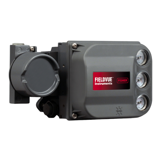
Fisher FIELDVUE DVC6200 Series, FIELDVUE DVC6200, FIELDVUE DVC6200f, FIELDVUE DVC6200p, FIELDVUE DVC6200 SIS Manual
Brand:
Fisher
| Category:
Controller
| Size: 2 MB
Table of Contents
Before You Begin
Install the DVC6200 on the Valve
Housing Variations
General Mounting Guidelines
Sliding-Stem Linear Actuators
Bracket Mounted
Integral Mounted Fisher Actuators
Quarter-Turn Rotary Actuators
Integral Mounted Fisher Actuators
Bracket Mounted
DVC6205 Remote Mount Base Unit Mounting
Pipestand Mounting
Wall Mounting
Connect the Pneumatic Tubing
Connect the Electrical Wires
FOUNDATION Fieldbus or PROFIBUS PA Devices
HART Devices
Position Transmitter or Discrete Switch
Remote Mount Feedback Unit
Smart Wireless THUM Adapter
Configure the Digital Valve Controller
Special Instructions for DVC6200 SIS
Special Instructions for DVC6200f PST
De-Energizeto Trip (DETT) DVC6200SIS, No Solenoid Valve
De-Energize to Trip (DETT) Digital Valve Controller and DETT Solenoid Valve
Energize to Trip (ETT) Digital Valve Controller and De-Energize to Trip (DETT) Solenoid Valve
Special Instructions for Solenoid Valve Health Monitoring
Wiring Configuration Option for Solenoid Valve Testing (DVC6200 SIS Only)
Documents / Resources
References
Advertisement
Fisher FIELDVUE DVC6200f Instruction Manual (340 pages)
Digital Valve Controller for FOUNDATION fieldbus
Brand:
Fisher
| Category:
Controller
| Size: 4 MB
Table of Contents
Table of Contents
3
Specifications
5
Section 1 Introduction and Specifications
5
Scope of Manual
5
Instrument Description
5
Using this Manual
8
Specifications
8
Related Information
12
Educational Services
12
Section 2 Installation
13
Installation
13
Mounting
13
Dvc6200F Digital Valve Controller
13
Dvc6205F Base Unit
16
DVC6215 Feedback Unit
18
Sliding-Stem Linear Actuators up to 210 MM (8.25 Inches) Travel
20
Fisher Rotary Actuators and Sliding-Stem Linear Actuators over 210 MM (8.25 Inches) Travel
22
GX Actuators
24
Quarter-Turn Rotary Actuators
27
Fisher 67CFR Filter Regulator
28
Pneumatic Connections
28
Pressure
28
Supply
29
Output Connection
30
Special Construction to Support Solenoid Valve Testing
31
Vent
32
Wiring and Electrical Connections
33
Connecting Fieldbus Wiring
33
Twisted-Shielded Pair
34
Quick Connect Cable Entry
35
Remote Travel Sensor Connections
36
Communication Connections
38
Simulate Enable Jumper
38
Commissioning Tag
39
Section 3 Basic Setup
41
Basic Setup
41
Transducer Block Mode
41
Protection
41
Device Setup
42
Performance Tuner
46
Section 4 Detailed Setup
47
Resource Block
47
Transducer Block
64
Analog Output Function Block
115
Controller
116
July
116
Proportional/Integral/Derivative
128
Function Block
128
Input Selector Function Block
147
Output Splitter Function Block
162
Analog Input Function Block
173
Mulitple Analog Input Function Block
185
Discrete Output Function Block
191
Discrete Input Function Block
203
Section 5 Calibration
215
Calibration Overview
215
Calibration
215
Auto
216
Manual
216
Relay
217
Supply Pressure Sensor
218
Pressure a or B Sensor
219
Variables and Diagnostics 219
221
Section 6 Viewing Device Variables and Diagnostics
221
View Lists
221
Resource Block
221
Device Diagnostics
222
Device Variables
224
Transducer Block
225
Device Diagnostics
226
Device Variables
231
Section 7 Maintenance and Troubleshooting
235
Troubleshooting
236
Replacing the Magnetic Feedback Assembly
236
Module Base Maintenance
236
Tools Required
236
Component Replacement
237
Removing the Module Base
237
July
237
Replacing the Module Base
238
Submodule Maintenance
239
I/P Converter
239
Printed Wiring Board (PWB) Assembly
241
Pneumatic Relay
242
Gauges, Pipe Plugs or Tire Valves
243
Terminal Box
243
Removing the Terminal Box
243
Replacing the Terminal Box
244
Stroking the Digital Valve Controller Output
244
DVC6215 Feedback Unit
244
Instrument Troubleshooting
245
Section 8 Parts
251
Parts Ordering
251
Parts Kits
251
Parts List
252
Housing
252
Common Parts
252
Module Base
253
I/P Converter Assembly
253
Relay
253
Terminal Box
253
PWB Assembly
254
Pressure Gauges, Pipe Plugs, or Tire Valve Assemblies
254
Appendix A Principle of Operation
261
Digital Valve Controller Operation
261
Appendix B Field Communicator Menu Tree
263
Menu Tree
277
Appendix C Plantweb Alerts
277
Alert Conditions
277
Plantweb Alerts
277
Alert Handling
277
Alert Reporting
279
Plantweb Alerts Set Block Status
279
Setting Plantweb Alerts
279
Using Plantweb Alerts
279
Communication
289
Appendix D FOUNDATION Fieldbus Communication
289
Function Block Overview
289
Function Blocks
289
Instrument Specific Blocks
290
Resource Blocks
290
Transducer Blocks
290
Block Modes
291
Explanation of Modes
292
Examples of Modes for Various Operation Statuses
293
Device Descriptions
293
Transducer Block Status and Limit Propagation
293
Status Propagation
294
Limit Propagation
294
Network Communication
295
Device Addressing
295
Link Active Scheduler
295
Device Communications
296
Scheduled Transfers
296
Unscheduled Transfers
297
Function Block Scheduling
298
Network Management
298
Installation
299
Appendix E Device Description Installation
299
250 Appendix E Device Description
299
Overview
299
Device Descriptions and Methods
300
Installing DD on a Deltav Professionalplus Workstation
300
Installing Dds on Other Fieldbus Host Systems
302
Displaying the Device Description Revision
303
Deltav System
305
Appendix F Operating with a Deltav System
305
Getting Started
305
Transducer Block Parameter - Configuration Index
306
Introduction
312
Software Functionality/System Requirements
312
Using AMS Device Manager
312
Methods
314
Accessing Parameters
314
Bringing the Device On-Line
317
Plantweb Alerts
317
Setting up Plantweb Alerts
317
Glossary
323
Index
327
Fisher FIELDVUE DVC6200f Quick Start Manual (44 pages)
Digital Valve Controllers
Brand:
Fisher
| Category:
Controller
| Size: 1 MB
Table of Contents
Table of Contents
1
Before You Begin
3
Step 1-Install the DVC6200 on the Valve
4
667 And 657
6
Bracket Mounted
6
For Sliding-Stem Linear Actuators Proceed to
6
Retaining
7
Actuators over 210 MM (8.25 Inches Travel)
8
Integral Mounted Fisher Actuators
9
Air-To-Open (667 Size 30I - 76I or GX)
10
Retaining
10
Air-To-Close (657 Size 30I - 70I or GX)
12
Retaining
12
For Quarter-Turn Rotary Actuators Proceed to
14
Integral Mounted Fisher Actuators
14
Bracket Mounted
15
For Remote Mount Applications, Proceed to Page 17 for DVC6205 Base Unit Mounting. Otherwise, Proceed to Step 2—Connect the Pneumatic Tubing on
16
Step 2-Connect the Pneumatic Tubing
19
Step 3-Connect the Electrical Wires
23
Special Instructions for DVC6200 SIS
35
Special Instructions for Dvc6200F PST
37
Special Instructions for Solenoid Valve Health Monitoring
43
Advertisement
Advertisement
Related Products
Fisher FIELDVUE DVC6200
Fisher FIELDVUE DVC6200 HW1
Fisher FIELDVUE DVC6200 HW2
Fisher FIELDVUE DVC6205 HW2
Fisher FIELDVUE DVC6205 HW1
Fisher Fieldvue DVC5010
Fisher Fieldvue DVC5020
Fisher D500243X012
Fisher FIELDVUE DLC3010
Fisher Fisher Fieldvue DLC3100
Fisher Categories
Controller
Control Unit
Metal Detector
Stereo System
Air Conditioner
More Fisher Manuals
Login
Sign In
OR
Sign in with Facebook
Sign in with Google
Upload manual
Upload from disk
Upload from URL