Elster EK280 Manuals
Manuals and User Guides for Elster EK280. We have 3 Elster EK280 manuals available for free PDF download: Applications Manual, Operating Manual

Elster EK280 Applications Manual (163 pages)
Brand: Elster
|
Category: Measuring Instruments
|
Size: 5 MB
Table of Contents
Advertisement
Elster EK280 Operating Manual (119 pages)
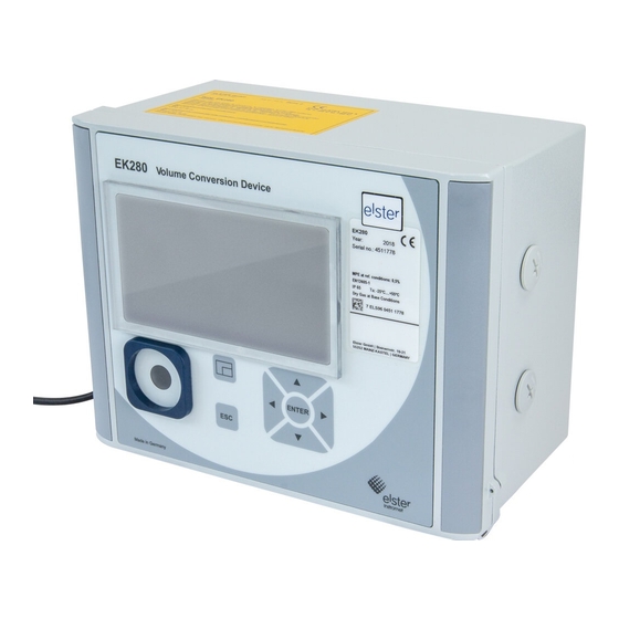
Volume conversion device
Brand: Elster
|
Category: Measuring Instruments
|
Size: 10 MB
Table of Contents

Elster EK280 Operating Manual (91 pages)
Volume conversion device
Brand: Elster
|
Category: Control Unit
|
Size: 4 MB
Table of Contents
Advertisement