Table of Contents
Advertisement
Quick Links
Advertisement
Table of Contents

Related Manuals for Elster EK280


Summary of Contents for Elster EK280
- Page 1 Operating manual Volume conversion device EK280...
- Page 2 Volume conversion device EK280 Operating manual: 73021209 Version: Issue date: 6.9.17 Software-Version: 2.50 or later...
-
Page 3: Table Of Contents
3 Technical data ..................20 3.1 General data ..................20 3.2 Power supply for EK280 without integrated power supply unit ..20 3.2.1 Battery power supply for the basic device ........... 20 3.2.2 Battery power supply for the integrated modem ........20 3.2.3 External power supply for the basic device ......... - Page 4 5.2.6 Connect outputs of the EK280 ............43 5.2.7 Earthing the EK280 housing ............... 44 5.2.8 Earthing the cable connections of the EK280 ........45 5.2.9 Additional measures for installation in zone 2 ........45 5.3 Putting into operation ............... 46 5.3.1 Configuration of measurement parameters ........
- Page 5 General 6.3 Basic principles ................59 6.3.1 Display ....................60 6.3.2 Button functions .................. 61 6.3.3 Data recall, display navigation ............. 62 6.3.4 Meaning of status symbols ..............63 6.3.5 Error messages when entering values ..........65 6.3.6 Access rights ..................66 6.4 Data register content ...............
-
Page 7: General
The data and material properties indicated serve as refer- ence values. These must be verified on a case-by-case ba- sis and adjusted as necessary. The EK280 Application Manual is available for you at www.ek280.de (-> Documents) for the commissioning of the various communication and device applications. -
Page 8: Electronic Hotline
In the event of faults, you can also contact the electronic hot- line. Tel. +49 (0) 6134 / 605-123 http://www.elster-instromet.com/de/support E-Mail: ElsterSupport@honeywell.com 1.4 Meaning of symbols 1.4.1 Safety information In this manual, safety information is denoted by the use of symbols. The safety information is introduced by signal words which identify the level of risk. -
Page 9: Tips And Recommendations
General 1.4.2 Tips and recommendations … provides useful tips and recommendations as well as in- formation for ensuring efficient and smooth operations. 1.5 Limitationof liability All of the information contained in this manual has been compiled under consideration of valid standards and regulations, the latest technological developments, and our many years of experience and expertise. -
Page 10: Scope Of Delivery
The free "enSuite" program also belongs to the accessories for the EK280 and is available under www.elster-instromet.com. This can be used to pro- gram the EK280 volume conversion device via its data interfaces to per- form advanced applications. -
Page 11: Storage
General 1.9 Storage CAUTION! Exceeding or falling below the valid temperature range for the batteries may impair performance. If the valid temperature range of the batteries during stor- age of the device is exceeded or fallen below, the perfor- mance of the batteries may be impaired. Therefore: –... -
Page 12: Safety
2.1 General The EK280 is an intrinsically safe device as per the ATEX Product Directive 94/9/EC and the ATEX Operating Directive 1999/92/EC EN, and is suitable for operation within the following explosive gas atmospheres: ... - Page 13 "associated equipment" present a risk of explosion. Therefore: – When using the EK280 in zone 1, it should only be con- nected to certified associated equipment as per the ATEX Product Directive 94/9/EC. – The EK280 should only be connected to the intrinsically-...
-
Page 14: Intended Use
This device is solely designed and constructed for the intended use de- scribed below. The volume conversion device EK280 is used to convert the gas volume read from a gas pipe under measurement conditions, into base conditions, as well as to allocate the measured quantities to tariffs. Furthermore, the device can also be used to measure, record and monitor additional varia- bles depending on the configuration set by the user. -
Page 15: Personnel
Safety 2.3 Personnel WARNING! Risk of injury to unqualified personnel. Improper use of the device may lead to significant personal injury or material damage. Therefore: – All works should solely be carried out by qualified per- sonnel. The following qualifications are used in the manual to denote different are- as of responsibility: ... -
Page 16: Personal Protective Equipment
Safety WARNING! Risk to unauthorized persons! Unauthorized persons, who do not meet the aforementioned criteria, will not be familiar with the risks in the working area. Therefore: – Please keep unauthorized persons away from the working area. – In cases of doubt, approach said person and direct them out of the working area. -
Page 17: Specific Risks
Safety 2.5 Specific risks The residual risks arising from the risk assessment will be listed below. Please observe the safety and warning information specified in the follow- ing chapters to reduce risks to health and to prevent dangerous situations from arising. WARNING! Misuse of batteries may present a risk of injury. -
Page 18: Environmental Protection
Safety 2.6 Environmental protection CAUTION! Environmentally hazardous substances! If environmentally hazardous substances are handled incorrectly this may cause significant damage to the environment, particularly if they are improperly disposed of. Therefore: – The instructions below should be observed at all times. –... - Page 19 Safety The operator must ensure that all employees who use the device have read and understood this manual. Furthermore, the operator must pro- vide training to personnel at regular intervals and inform them of the po- tential risks. The operator of the entire plant in which the device is to be integrated, must provide personnel with the necessary protective equipment.
-
Page 20: Technical Data
Permissible ambient temperature range -25 ... +55 °C Permissible gas temperature range -30 ... +60 °C 3.2 Power supply for EK280 without integrated power supply unit 3.2.1 Battery power supply for the basic device Data Value Unit Voltage General nominal capacity 16.5... -
Page 21: External Power Supply For The Basic Device
7.5 …8.5 Supply voltage Supply current, maximum 3.3 Power supply for EK280 with integrated power supply unit 3.3.1 Battery power supply for the basic device Batteries for switching to battery mode in the event of a power failure: see chapter 3.2.1 "Battery power supply for the basic device"... -
Page 22: Pressure Sensor
16 ... 80 bar abs. 105 bar abs. The pressure sensor is available as both an external and internal model. Further details can be found under www.elster- instromet.com or chapter "Assembly, Connection and Put- ting into Operation". 3.4.1.2 Relative pressure ranges... -
Page 23: Pressure Sensor Type 17002
… 7 bar abs. 10 bar abs. The pressure sensor is available as both an external and internal model. Further details can be found under www.elster-instromet.com or chapter " Assembly, Connection and Putting into Operation". 3.5 Temperature sensor Data Value Unit -30 …... -
Page 24: Hf Pulse Inputs (High Frequency)
Technical data Data Value Unit Open-circuit voltage U MΩ Internal resistance R μA Short circuit current I Resistance R kΩ Switch point "ON": max. Voltage U max. Resistance R MΩ Switch point "OFF": min. Voltage U min. -
Page 25: Digital Outputs
Technical data 3.7 Digital outputs The digital outputs DA2 and DA3 can be configured as low or high frequen- cy pulse or signal outputs. The digital outputs DA1 and DA4 can exclusively be configured as low fre- quency pulse or signal outputs. 3.7.1 Nominal data Data Value... -
Page 26: Interfaces
Technical data 3.8 Interfaces 3.8.1 Serial optical interface Data Value Unit Baud rate 9600 Format 1 start bit, 1 parity bit, 1 stop bit 3.8.2 Serial electrical interface Data Value Adjustable types RS232 or RS485 3.8.2.1 Technical Data of the RS485 Interface Data Value Operating modes... -
Page 27: Measurement Conditions
Directive (MID). The label is placed on the front panel of the de- vice (see Construction and Function chapter). 3.10.1 Type label of the volume corrector The type label of the EK280 relating to its function as a volume corrector, contains the following information: 1 Type designation EK280... -
Page 28: Atex Marking
Technical data 3.10.2 ATEX marking The plate for the "Ex" marking of the EK280 is located on the top panel of the device housing. 3.10.2.1 Zone 1 (without integrated power supply unit) ELSTER GmbH II 1 G 55252 Mainz- Kastel... -
Page 29: Device Software Identification
Technical data 3.10.3 Device software identification Move the cursor using the arrow keys to the "Serv." register and to the values "Vers" (device software version) and "Chk" (checksum) via the following path: Serv. Identification Volume Converter "Vers" or "Chk" ... -
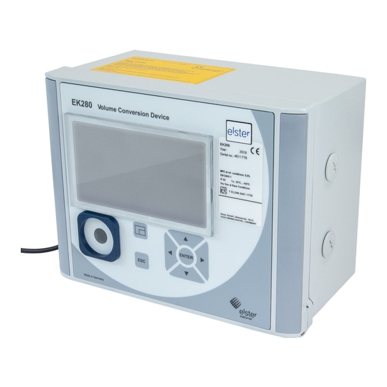
Page 30: Construction And Function
Construction and Function 4 Construction and Function 4.1 External view 1 Display 2 Cable bushings for the connection of additional components Identification label 3 Optical interface 4 Escape button "ESC" 5 Enter button "ENTER" 6 Function key 7 Arrow keys , , , Instromet 8 Pressure sensor 9 Cable bushing... -
Page 31: Short Description
Construction and Function 4.3 Short description The volume conversion device EK280 is an explosion-protected electronic device that takes the volume of gas determined by an external meter at measurement conditions to calculate the volume at base conditions and therefore the energy portion of the respective gas volume. -
Page 32: Assembly, Connection And Putting Into Operation
– Do not open when an explosive atmosphere may be pre- sent! – Electrostatic hazard: Do not rub! The EK280 can either be mounted on a gas meter, on a pipe- line, or on a wall. Should problems arise during assembly, e.g. with regard to the selection of suitable assembly tools, please contact our customer service team (see "General"... -
Page 33: Assembly On A Gas Meter
Assembly, Connection and Putting into Operation 5.1.1 Assembly on a gas meter Mount the EK280 on a gas meter using a mounting bracket (see Appendix) as well as the corresponding cylinder screws and square nuts. 1. Using two M5 x 10 mm (Fig. 6: 4 ) cylinder screws, attach the mount- ing bracket (Fig. -
Page 34: Assembly On A Wall
The three-way valve available from Elster is constructed as follows: i1 : From the meter: From the pressure Prüfen mit... -
Page 35: Connection
The connection of non intrinsically-safe or non- associated equipment presents a risk of explosion! The operation of the EK280 in zones 1 and 2 and the con- nection of non intrinsically-safe equipment which exceeds those conditions and limit values specified in the declaration of conformity, presents a risk of explosion. -
Page 36: Connecting The Gas Meter
EK280 (see "Construction and Function" chapter). Fur- ther details can be found under www.elster-instromet.com. - Page 37 If the power supply is in a functioning order, the volumes and flows (Vb, Vm, Qb, Qm) will be measured with the high frequency pulse transducer. In the event of a failure of the external power supply, the EK280 will automati- cally switch to the low frequency pulse transducer.
-
Page 38: Sealing The Input Terminals
Assembly, Connection and Putting into Operation 1. Connect the low frequency pulse transducer of the gas meter to the "DE1" terminal ( 1 ) of the EK280. 2. Connect the high frequency pulse transducer of the gas meter to the "DE2"... - Page 39 Assembly, Connection and Putting into Operation 5.2.3.1 Connection to a standard temperature sensor pocket 1. Insert the temperature sensor Pt500 4 into the temperature sen- sor pocket 5 (see Appendix). 2. Fasten the temperature sensor using the capstan screw 2 and screw connections provided 6 .
-
Page 40: Connecting The Pressure Pipe
Assembly, Connection and Putting into Operation 5.2.4 Connecting the pressure pipe Any national requirements must be observed when con- necting the pressure pipes. The requirements of the PTB Testing Instructions, Volume 20, Electronic volume conversion device for gas, Chapter 5, shall apply to Germany. -
Page 41: Connecting The Power Supply
"associated equipment" present a risk of explosion. Therefore: – When using the EK280 in zone 1, it should only be con- nected to certified associated equipment as per the ATEX Product Directive 94/9/EC. – The EK280 should only be connected to the intrinsically-... - Page 42 Assembly, Connection and Putting into Operation 5.2.5.2 Power supply for the EK280 with integrated power supply unit DANGER! Danger to life from electrical current! Touching live parts poses an imminent danger to life. Therefore: – Works on the electrical components of the device, i.e.
-
Page 43: Connect Outputs Of The Ek280
Assembly, Connection and Putting into Operation 5.2.6 Connect outputs of the EK280 The cable core diameter for the connection to the EK280 outputs is 0.33 … 2.5 mm Different downstream devices can be connected to the digi- tal outputs of the EK280. The outputs are preconfigured for this purpose (see chapter 5.3.1.13). -
Page 44: Earthing The Ek280 Housing
Fig. 19 5.2.7 Earthing the EK280 housing The housing of the EK280 must always be earthed. A M6 screw is provided for this on the left-hand side of the housing. 1. The earth-cable must have a minimum diameter of 4mm 2. -
Page 45: Earthing The Cable Connections Of The Ek280
4.5 mm M16 and M20, metal: 8 mm M16, plastic: 8 mm The ATEX category "II 1 G" models of the EK280 (without in-built power supply unit) should be installed in both zones 1 and 2 without these addi- tional measures. -
Page 46: Putting Into Operation
Assembly, Connection and Putting into Operation 5.3 Putting into operation 5.3.1 Configuration of measurement parameters If the EK280 is subject to calibration regulations, the works described below should only be performed by legally author- ized individuals. The necessary measurement parameters can be adjusted using the free configuration program "enSuite"... - Page 47 5.3.1.3 Activating encoder mode If an encoder is connected as per 5.2.1.2, the encoder mode is activated as follows: Start the "Auto Detect" function using the keyboard of the EK280 as fol- lows: Move the cursor to the "Serv." register and to the value "Md.I1" (input mode) via the following path: Serv.
- Page 48 Assembly, Connection and Putting into Operation Unlike the "Auto Detect" function, you can also select the connected en- coder type directly under "Md.I1". Serv. Volume Inputs Input 1 Md.I1 The following encoder types can be selected: Md.I1 Meaning Enc.Namur a...
- Page 49 In order to control the recording of the volume at measurement conditions, the EK280 meter can be set once to the same value as the gas meter if the administrator lock is open. It is always possible to set the volume if the cali- bration lock is open: ...
- Page 50 „Vm_n“ (Vm new value) are set to default value. 5.3.1.8 Setting the volume at base conditions For the EK280 volume conversion device, there is the option available when commissioning the device to set the volume at base conditions meter once if the administrator lock is open. It is always possible to set the vol- ume if the calibration lock is open: ...
- Page 51 Assembly, Connection and Putting into Operation Once you have changed all of the digits, press the ENTER key in order to confirm your entry. The entry can be cancelled by pressing the ESC key. In order to accept the set value, move the cursor to the value „Store“ Press the ENTER key ...
- Page 52 Assembly, Connection and Putting into Operation Md.K Meaning fix value No calculation of compressibility. The adjustable value "K.F" will be used. S-Gerg-88 Calculation of compressibility as per S-Gerg-88 AGA- NX19 Calculation of compressibility as per AGA-NX19 AGA-8 GC1 AGA8 Gross Characterization Method 1 AGA-8 GC2 AGA8 Gross Characterization Method 2 AGA-NX19-HW...
- Page 53 Aside from the settings described here, a range of other func- tions can be configured for the outputs, e.g. high frequency or time-synchronous pulses. A complete description can be found in the EK280 Application Manual that can be downloaded under www.elster- instromet.com.
- Page 54 All measurement archives (no logs) will be deleted. In order to ensure that the archive is not accidentally deleted, the serial number of the EK280 must be entered whilst the calibration lock is open (the number is located on EK280 identification plate).
-
Page 55: Sealing
To discover the wide range of possibilities for remote data transfer to a con- trol center via the integrated modem or via a device connected to the ter- minal interface, please follow the corresponding instructions in the EK280 Application Manual, which you can download from www.elster- instromet.com. - Page 56 Assembly, Connection and Putting into Operation 5.3.2.2 Internal view Sealing point to secure the calibration switch. Sealing points to secure the circuit board cover Sealing points to secure the sensor covers for the pressure and temperature sensors. Sealing points to secure the terminal covers of the inputs, outputs and inter- faces if necessary.
-
Page 57: Closing The Housing
Fig. 22 5.3.4 Verifying assembly and connection WARNING! Risk as a result of incorrect assembly and connection Incorrect assembly and connection of the EK280 may lead to life-threatening situations. Therefore: – Assemble and connect the EK280 correctly. – Sealing should solely be carried out by a calibration of- ficer. -
Page 58: Operation
are authorized to read and take note of values and parameters using the control elements of the EK280, and to perform changes which are not subject to calibration regulations. -
Page 59: Calibration Officers
is authorized to read and take note of values and parameters using the control elements of the EK280, and to perform changes which are not subject to calibration regulations. 6.3 Basic principles As already explained in the "Construction and Function"... -
Page 60: Display
Operation 6.3.1 Display The display is divided into the five registers "Main", "Cust.", "Admin", "Serv." and "Ctrl." under which measurements, settings and other data are displayed. Fig. 24 Display layout Device status Battery charge status Frozen display Active register External power supply Inactive register Reception strength of the ex- Cursor... -
Page 61: Button Functions
Operation 6.3.2 Button functions The pressure and arrow buttons have the following functions: Button Function Jump right to another data list. Jump to the second part of a two-part value. Jump down through a data list. ... -
Page 62: Data Recall, Display Navigation
Operation 6.3.3 Data recall, display navigation Using the arrow keys , , , , you can move the cursor around the display and switch to the other values. By pressing the ESC button one or more times, you will be directed to the "Main", "Cust.", "Admin", "Serv."... -
Page 63: Meaning Of Status Symbols
Operation 6.3.4 Meaning of status symbols The status symbols displayed in the first line have the following meaning: Fig. 26: Status symbols in the display Symbol Meaning In the upper left-hand side of the screen, individual letters are displayed as symbols for the following signals: No special message. - Page 64 External power supply If this symbol appears, the EK280 is being supplied power from an external unit connected to the terminals. Signal strength of the radio network for the external modem (connected to the terminals).
-
Page 65: Error Messages When Entering Values
Operation 6.3.5 Error messages when entering values If a value has been entered incorrectly via the keyboard, input error mes- sages will be displayed. This is shown as follows: --x-- with x = error code according to the following table Code Description The archive is empty. -
Page 66: Access Rights
The calibration lock is designed as a button which is positioned inside the EK280 housing underneath the circuit board cover. It can be protected with an adhesive label (see chapter 5.3.1.1, "Opening the calibration lock"). The calibration lock is opened by pressing the button ("P" symbol flashes in the display) and is closed again by pressing the same button ("P"... - Page 67 Operation 6.3.6.2 Certification data log The certification data log is activated as standard but can also be disabled. The corresponding parameters will then be protected by the calibration lock. Using the "certification data log" as per PTBA 50.7, several parameters subject to calibration regulations can also be adjusted when the calibration lock is closed.
-
Page 68: Data Register Content
Operation 6.4 Data register content 6.4.1 Access rights The "access" column in the tables in the following chapter describes which lock must be opened in order to change a parameter. All parameter chan- ges are saved in a log. Access Meaning Calibration officer Certification data log Administrator... - Page 69 The calculated compressibility ratio factor is used to calculate the volume at base conditions. The EK280 supports several equations to calculate the compressibility ratio factor. The corresponding equation is determined by the applicable guide- lines and standards for the area of application of the device. This can be adjusted at the ordering or commissioning phase (...
-
Page 70: Cust." Register (Customer)
Operation 6.4.3 "Cust." register (Customer) This register is used to display and check special device settings and con- ditions. This application is provided for gas customers. This register can be freely programed by the user via the enSuite configu- ration software. The following parameters are programed in-house: Display Meaning... - Page 71 Operation 6.4.3.3 SReg – Status register (total) In the status register all messages since the last manual clearing are col- lected. Here, you can also see what has happened, for example, since the last station inspection. The messages can be cleared at the device (Serv. - >...
-
Page 72: Admin" Register (Administrator)
Operation If an encoder is connected: If the meter reading changes every two seconds or less, the measurement inaccuracy of Qm will be max. 1%. If the meter reading changes every 200 seconds or less, the measurement inaccuracy will be max. 10%. This can be reduced by decreasing the measurement cycle (Serv. -
Page 73: Serv." Register (Service)
Operation 6.4.5 "Serv." register (service) This register is used to display, check and configure special device settings and conditions. This application is only intended for service technicians (specialists) or a calibration officer for putting the device into operation or maintenance. Display Meaning Volume... -
Page 74: Ctrl." Register (Control)
Operation 6.4.6 "Ctrl." register (Control) This register is used to monitor special device settings. This application is only intended for service technicians (specialists) or a calibration officer for putting the device into operation or maintenance. Display Value Unit Addres cess St.AL Administrator lock: State / close 3:170... - Page 75 Operation 6.4.6.4 Menu - Selection of the display menu In an as-delivered condition, the display of the EK280 has the following five registers: "Main", "Cust.”, "Admin", "Serv." and "Ctrl.". Registers can be displayed and hidden for certain purposes using the "Menu" value.
- Page 76 Operation 6.4.6.5 Main – Content of the "Main" register The content of the "Main" display register can be adjusted here. The default setting is "volume+meas.”. This corresponds to the content dis- played in chapter 6.3.1. Display Meaning vol- - The following are displayed: Volume at base condi- ume+meas.
-
Page 77: Maintenance
Maintenance 7 Maintenance 7.1 Safety DANGER! Danger to life from electrical current! Touching live parts poses an imminent danger to life. Dam- age to the insulation or individual components may be life- threatening. Therefore: – Safely protect electrical connections and live compo- nents against possible human contact. - Page 78 Maintenance WARNING! Misuse of batteries may present a risk of injury. Special care must be taken when handling batteries. Therefore: – Do not throw the batteries into the fire or expose these to high temperatures. There is a risk of explosion. –...
-
Page 79: Personnel
Maintenance 7.1.1 Personnel Maintenance works must be carried out correctly. The maintenance works described in this document should solely be carried out by specialized electricians (see "Operation" chapter). WARNING! Risk of injury if maintenance works are carried out in- correctly. -
Page 80: Testing And Changing Device Batteries
In an as-delivered condition, two batteries are connected to the base board of the EK280. To double the service life of the batteries, two additional batteries can be connected. You should always connect at least two batteries (to X10 and X13 or X11 and X14) to the EK280. - Page 81 3.2.1), the service life should display at least 60 months. If not, compare the settings with those for standard measurement conditions and repeat step 11 if necessary. Please ensure that the new batteries are connected cor- rectly and are in a fixed position inside the EK280.
-
Page 82: Entering The Battery Capacity
Maintenance CAUTION! Material damage may arise through improper closing of the device! Improper closing of the device may lead to material damage as a result of cable connections being squashed. Therefore: – When closing, ensure that the cable ducts are positioned correctly. -
Page 83: Display Remaining Battery Power
Maintenance For closing the administrator lock move the cursor to the "Admin" regis- ter and to the "St.AL" value (status administrator lock) via the following path: Admin. Device settings Access St.AL Press the ENTER button ”open“ will start to flash. ... -
Page 84: Faults
For faults, which cannot be resolved by the instructions be- low, please contact our customer service team (see chapter General) or our Electronic Hotline: Tel. +49 (0) 6134 / 605-123 http://www.elster-instromet.com/de/support E-Mail: ElsterSupport@honeywell.com 8.1 Safety DANGER! Danger to life from electrical current! Touching live parts poses an imminent danger to life. -
Page 85: Personal Protective Equipment
Faults Works on the electrical appliance may only be carried out by qualified electricians. 8.1.2 Personal protective equipment When eliminating faults on the device, the necessary personal protec- tive equipment for the work must be worn inside the respective plant. ... -
Page 86: Fault And Other Status Messages
8.2 Fault and other status messages Faults (synonymously used here for "alarms") during the operation of the EK280, can be identified by means of status symbols in the first line of the display (see chapter 6.3.4). You can obtain further information and messages under the current status "Stat"... - Page 87 Please contact the Elster support (see chapter 1.3 "Customer service"). b) Warnings: Data restore The batteries of the EK280 are intermittently dropping out. As a result of this, the time has not changed and no measurement and volume conversion have happened. However, all data is available.
- Page 88 "Customer service"). Sett. error The programing of the device has generated an unusable com- bination of settings. Please contact the Elster support (see chapter 1.3 "Customer service"). I2 Warn.sig. If an input has been configured as a warning input, this I3 Warn.sig.
- Page 89 If this message appears for more than several minutes, the function "Automatically set time via RDT" is activated. However, if this does not work, please contact the Elster support (see chapter 1.3 "Customer service").
- Page 90 The administrator / customer lock is open. Cust.lock o. Bat. operat. The EK280 is in battery mode. This signal is primarily used to inform a remote data transmission system that the batteries run down more quickly during long periods of data transmission.
-
Page 91: Appendix
Set mounting bracket EK220/280 for MI-2 73 021 952 Set mounting bracket EK220/280 for Rabo 73 021 953 Set mounting bracket EK280 for S1/Encoder 73 021 954 Set Bracket EK/DL for pipe mounting 73 021 955 Universal bracket with pipe clamps for pipe mounting... -
Page 92: Temperature Sensor Pockets
Device battery module 13 Ah 73 015 774 Device battery module 13 Ah 730 23 225 16 Ah battery module for the modem of the EK280 without 73 021 211 integrated power supply unit 13 Ah battery module for connection to the integrated... -
Page 93: Ec Declaration Of Conformity
Appendix 9.2 EC Declaration of Conformity... -
Page 94: Atex Type Examination Certificate
Appendix 9.3 ATEX Type Examination Certificate 9.3.1 Zone 1... - Page 95 Appendix...
- Page 96 Appendix...
- Page 97 Appendix...
- Page 98 Appendix...
- Page 99 Appendix...
- Page 100 Appendix...
- Page 101 Appendix...
- Page 102 Appendix...
- Page 103 Appendix...
- Page 104 Appendix...
- Page 105 Appendix...
- Page 106 Appendix...
- Page 107 Appendix...
- Page 108 Appendix...
-
Page 109: Zone 2
Appendix 9.3.2 Zone 2... - Page 110 Appendix...
- Page 111 Appendix...
- Page 112 Appendix...
- Page 113 Appendix...
- Page 114 Appendix...
- Page 115 Appendix...
- Page 116 Appendix...
- Page 117 Appendix...
- Page 118 Appendix...
- Page 119 Appendix...
Need help?
Do you have a question about the EK280 and is the answer not in the manual?
Questions and answers