Sign In
Upload
Manuals
Brands
Edgetech Manuals
Sonar
4200
User Manuals: Edgetech 4200 Side Scan Sonar
Manuals and User Guides for Edgetech 4200 Side Scan Sonar. We have
1
Edgetech 4200 Side Scan Sonar manual available for free PDF download: User Hardware Manual
Edgetech 4200 User Hardware Manual (142 pages)
SIDE SCAN SONAR SYSTEM
Brand:
Edgetech
| Category:
Sonar
| Size: 10 MB
Table of Contents
Warning - Read this First
3
Radiation
3
High Voltages
3
Improper Line Voltage
3
Hardware Variations and Compatibility
4
Preface
5
Purpose of this Manual
5
Warnings, Cautions, and Notes
6
Liability
6
Revision History
6
Warranty Statement
7
Software Service Overview
8
Software Updates and Enhancements
8
Returned Material Authorization
9
RMA Purpose
9
Customer Service
9
Company Background
11
Table of Contents
12
List of Figures
18
Overview
22
Single Pulse Versus Multi Pulse Performance
22
4200 Series Applications
23
Main System Components
23
Figure 1-1: 4200 Series Systems Being Readied Deployed
23
Figure 1-2: Three 4200 Topside Processor Options
24
Topside Processors
25
4200 Rack Mount Processor
25
4200-P Portable Topside Processor
25
701-DL Digital Link
26
Tow Vehicles
26
4200-SP Tow Vehicle
27
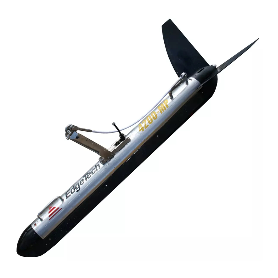
Figure 1-3: 4200 SP and MP Tow Vehicle Diagram
27
4200-MP Tow Vehicle
28
Tow Cables
28
Optional Equipment
28
Figure 1-4: Kevlar Reinforced Tow Cable
28
Acoustic Tracking System
29
Depressor Wing
29
Figure 1-5: Depressor Wing
29
Magnetometer
29
Power Loss Pinger
30
Pressure Sensor
30
Responder
30
Specifications
31
4200 Series Topside Processors
31
Table 2-1: 4200 Series Topside Processor Specifications
32
4200 Rack Mount Topside Processor
33
Power
33
Figure 2-1: 4200 Rack Mount Processor Chassis
33
Figure 2-2: 4200 Rack Mount Processor Electronics Block Diagram
34
VDC Power Supply
35
Computer Power Supply
35
ADSL Modem
35
Net Burner
35
Central Processing Unit
35
Hard Drives
35
4200-P Portable Topside Processor
35
Power
36
VDC Power Supply
36
AC Line Filter
36
ADSL Modem
36
Figure 2-3: 4200-P Portable Topside Processor Chassis
37
Figure 2-4: 4200-P Portable Topside Processor General Block Electronics Diagram
38
Figure 2-5: 4200-P Portable Topside Processor Wiring Diagram
39
Net Burner
40
Wireless Router
40
701-DL Digital Link
40
Figure 2-6: 701-DL Internal Hardware
40
Figure 2-7: 701 DL Digital Link Electronics Block Diagram
41
Figure 2-8: 701 DL Digital Link Wiring Diagram
42
ADSL Modem
43
Net Burner
43
Power
43
Power Entry
43
VDC Power Supply
43
4200 Series Tow Vehicle
43
Table 2-2: 4200 Series Tow Vehicle Specification
45
Figure 2-9: Tow Vehicle Electronics Chassis
46
Figure 2-10: Tow Vehicle Electronics Wiring Diagram
47
Figure 2-11: Tow Vehicle Electronics Block Diagram
48
ADSL Modem
49
Power Distribution
49
T/R Switch
49
Central Processing Unit
50
Compass
50
DDC
50
Power Amplifier
50
Side Scan Board
50
Sonar Interface
50
Optional Responder
51
Cables
51
Optional Depressor Wing
51
Mechanical Drawings
51
Table 2-3: Depressor Wing Specifications
51
Figure 2-12: 4200 Tow Fish ICD - 0020346
52
Figure 2-13: 4200 Tow Fish with 2Ft V-Wing Configuration - 0020346
53
Figure 2-14: 4200 Tow Fish with 3Ft V-Wing Configuration - 0020346
54
Figure 2-15: 4200 Tow Fish with Long Arm and Tail Configuration - 0020346
55
Figure 2-16: 4200 Tow Fish with 2Ft V-Wing and Long Tail Fins Configuration - 0020346
56
Figure 2-17: 4200 Tow Fish with 3Ft V-Wing and Long Tail Fins Configuration - 0020346
57
Setup and Activation
58
Unpacking and Inspecting
58
Power Requirements
59
Use of an Uninterrupted Power Supply
59
Changing to a Non-US Power Plug
60
Navigation Interface
60
Topside Processor Placement
60
Table 3-1: AC Power Cord Wiring
60
Topside Processor Controls and Indicators
61
4200 Rack Mount Topside Processor Controls and Indicators
61
Figure 3-1: 4200 Rack Mount Topside Processor Rear Panel
62
4200-P Portable Topside Processor Controls and Indicators
64
Figure 3-3: 4200-P Portable Topside Side Panel
65
701-DL Digital Link Controls and Indicators
66
Figure 3-4: 701-DL Front and Back Panels
67
Topside Processor Connections
68
4200 Rack Mount Topside Processor Connections
68
4200-P Portable Topside Processor Connections
68
701-DL Digital Link Connections
69
TCP/IP Address Settings
69
Table 3-2: Topside Processor ETHERNET Devices TCP/IP Addresses
69
Connecting the System Components
70
Table 3-3: Tow Vehicle ETHERNET Devices IP Addresses
70
Figure 3-5: Example of 4200 System Connection Diagram
71
Figure 3-6: Topside Processor Cables
72
Connecting and Attaching the Tow Cable to the Tow Vehicle
73
Figure 3-7: Tow Vehicle with Tow Cable Connected and Attached
73
Installing a Depressor Wing and Connecting the Tow Cable
73
Figure 3-8: Tow Vehicle with Depressor Wing and Safety Grip Attached
74
Figure 3-9: Depressor Wing Angle Adjustments
75
Connecting the 4200 Rack Mount Topside Processor
76
Connecting the 4200-P Portable Topside Processor
76
Connecting the 701-DL Digital Link
77
Selecting Negative Edge Triggering for the Optional Responder
78
System Activation and Test
78
Activating the 4200 Rack Mount System
78
Activating the 4200-P Portable System
78
Activating the 701-DL Digital Link System
79
Performing the Pre-Deployment Checks
79
Figure 3-10: Towfish Control Tab- Discover 4200-SP
80
Figure 3-11: Towfish Control Tab- Discover 4200-MP
80
Tow Vehicle Deployment
81
Figure 3-12: 4200-MP Tow Vehicle Being Deployed
82
Tow Vehicle Recovery
83
Figure 3-13: Bottom Track Tab
83
Figure 3-14: 4200 Tow Vehicle with Optional Depressor Wing Being Recovered
84
Maintenance
85
Clean the 4200 Topside Processor
85
Clean the Air Filter in the 4200 Rack Mount Topside Processor
85
Clean the 4200-P Portable Topside Processor
85
Clean the 701-DL Digital Link
85
Inspect and Clean the Tow Vehicle and Tow Cable after Use
85
Inspect and Clean the Underwater Connectors
86
Storage
86
Recommended Spares
86
Troubleshooting
87
Restoring the Operating System
87
Disassembling and Reassembling the Tow Vehicle
87
Disassembling the Tow Vehicle
88
Figure 5-1: Removing the Tail Fins from the Tail Cone
88
Figure 5-2: Removing the Tail Cone Screws
89
Figure 5-3: Removing the Tail Cone
89
Figure 5-4: Disconnecting the Transducer Cables
90
Figure 5-5: Removing the Finish Washer
90
Figure 5-6: Pulling out the Nylon Retaining Line
91
Figure 5-7: Attaching the End Cap Removal Handle
91
Figure 5-8: End Cap Extracted from Housing
92
Figure 5-9: Tow Cable and Option Connectors
92
Reassembling the Tow Vehicle
93
Calibrating the Compass
94
Topside Processor Troubleshooting Guides
94
4200 Rack Mount Topside Processor Troubleshooting Guide
94
Table 5-1: 4200 Rack Mount Topside Processor Troubleshooting Guide
95
4200-P Portable Topside Processor Troubleshooting Guide
96
Table 5-2: 4200-P Topside Troubleshooting Guide
96
701-DL Digital Lin
97
Tow Vehicle Troubleshooting Guide
97
Table 5-3: 701-DL Troubleshooting Guide
97
Required Equipment
98
Transmission Verification
98
Command and Data Link
99
Sonar Processor and Data Link
99
Topside Power Unit
99
Data Link
100
Figure 5-10: Sockblast Window
100
Tow Fish
101
Tow Cable Troubleshooting
103
Part Numbers for Major Topside Components
105
Figure 3-2: 4200 Rack Mount
105
Table 5-4: Part Numbers for Major Topside Processor Components
105
Part Numbers for Major Tow Vehicle Components
106
Tow Vehicle Outline Drawings
106
Table 5-5: Part Numbers for Major Tow Vehicle Components
106
Appendix A: Diagrams
107
Advanced Users Setup Guides
107
Zoom ADSL X3 Modem Model 5560A Setup
107
Zoom ADSL X3 Modem Model 5560 Setup
108
Zoom ADSL X5 Modem Model 5564 Setup
109
Detailed Zoom Modem Setup Guide
111
Adding a Temporary Host IP Address
111
Figure
111
Zoom X3 and X5 ADSL Modem Models 5560A and 5654 Setup - HTML Accessible Configuration
114
Zoom X3 ADSL Modem Model 5560A Setup-Telnet-Only Accessible Configuration
117
Zoom X5 ADSL Modem Model 5654 Setup-Telnet-Only Accessible Configuration
118
Zoom X3 ADSL Modem Model 5560 Setup
119
Figure
123
Remove Temporary Host IP Address
125
Table B-1: Model 4325E Responder Specifications
126
Figure B-1: Model 4325E Responder Beam Pattern
127
Appendix B:model 4325E Responder
128
Operation
128
Internally Triggered Operation
128
Externally Triggered Operation
128
Setup
128
External Trigger Input
129
Figure
129
Responder Internal Components
129
Figure B-2: Responder Assembly
130
Appendix C: Hardware Diagrams
131
Cables
131
Figure C-1: Kevlar Reinforced Tow Cable
132
Figure C-2: Armored Tow Cable, Kellems Grip, Terminated both Ends
133
Figure C-3: Armored Tow Cable, Kellems Grip, Unterminated Topside
134
Figure C-4: Armored Tow Cable, PMI Grip, Unterminated
135
Figure C-5: AC Power Cable
136
Figure C-6: DC Power/Ethernet Cable
137
Tow Vehicle Outline Drawings
138
Figure C-7: 4200 Tail Fin, Short Tow Arm
139
Figure C-8: 4200 Tail Fin, Style B
140
Appendix D: Backup and Restore
141
Backing up the System Drive
141
Restoring the System Drive
141
Advertisement
Advertisement
Related Products
EdgeTech 4125 SIDE SCAN
Edgetech 4600
EDGE Tech 4125 Series
Edgetech 4125I
Edgetech 4125i-P TOPSIDE
Edgetech 4125i-RM TOPSIDE
Edgetech 4205
Edgetech 4200-FS
Edgetech 4380 MULTIBEACON
EdgeTech 2000-CSS
Edgetech Categories
Marine Equipment
Sonar
Measuring Instruments
Fishing Equipment
Scanner
More Edgetech Manuals
Login
Sign In
OR
Sign in with Facebook
Sign in with Google
Upload manual
Upload from disk
Upload from URL