Sign In
Upload
Manuals
Brands
Edgetech Manuals
Scanner
4205
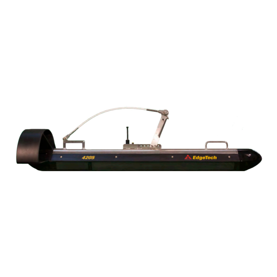
Edgetech 4205 Manuals
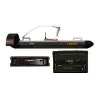
Manuals and User Guides for Edgetech 4205. We have
4
Edgetech 4205 manuals available for free PDF download: User Hardware Manual, Manual
Edgetech 4205 User Hardware Manual (108 pages)
SIDE SCAN SYSTEM
Brand:
Edgetech
| Category:
Scanner
| Size: 6 MB
Table of Contents
Attention - Read this First
3
Warnings, Cautions, and Notes
3
Hardware Variations and Compatibility
4
About this Document
5
Liability
5
Revision History
5
Warranty Statement
6
Software Service Overview
7
Software Updates and Enhancements
7
Returned Material Authorization
8
RMA Purpose
8
Customer Service
9
Company Background
10
Table of Contents
11
List of Figures
15
1 Overview
19
4205 Side Scan Sonar System Applications
20
Main System Components
20
Topside Processor
20
Figure 1-1: Starmux IV Rackmount with Keyboard, Mouse and LCD Monitor
21
Figure 1-2: 701-DL Rack Mount with Keyboard, Trackball, and LCD Monitor
22
Figure 1-3: Starmux Rackmount with Keyboard, Trackball Mouse, and Display
22
Towfish
23
Figure 1-4: 4205 Towfish Side View
23
Figure 1-5: 4205 Towfish Forward View
23
Figure 1-6: 4205 Towfish Aft View
23
Table 1-1: 4205 Towfish Options
23
Tow Cables
24
Optional Equipment
24
Figure 1-7: Kevlar Tow Cable
24
Acoustic Tracking System
25
Depressor Wing
25
Magnetometer Interface
25
Pressure Sensor
25
Responder
25
SGB Compass
25
2 Specifications
26
4205 Sonar Performance Specifications
26
Table 2-1: 4205 Sonar Performance Specifications
26
Towfish Specifications
27
4205 Topside Specifications
27
Table 2-2: Towfish Specifications
27
Table 2-3: Starmux IV Specifications
28
Table 2-4: 701-DL Specification
30
Armored Tow Cable Specifications
31
Kevlar Tow Cable Specifications
31
Table 2-5: Starmux III Specifications Cable Specifications
31
Table 2-6: Kevlar Tow Cable Specifications
31
Table 2-7: Armored Tow Cable Specifications
31
Mechanical Drawings
32
4205 Towfish Drawings
32
Figure 2-1: 4205 Towfish ICD - 0020967
32
Figure 2-2: 4205 with 2Ft Depressor - 0021208
33
Electronic Bottle and Connection Drawings
34
Figure 2-3: 4205 MPMT Towfish Endcap Connections
34
Figure 2-4: 4205 MPMT Tri-Frequency Endcap Connections
35
Figure 2-6: 4205 MPMT and Tri-Frequency Tow Cable Connections with Pinouts
37
Cable Drawings
39
Topside Digital Link Drawings
43
Figure 2-8: Starmux IV ICD
43
Figure 2-9: Starmux IV DL in Case
44
Figure 2-10: 701 DL
45
3 Technical Descriptions
46
Towfish Technical Description
46
Figure 3-1: 4205 MPMT Towfish Diagram
46
4205 Tri-Frequency & Single Pulse Towfish
47
4205-MPMT Towfish
47
Topside Technical Descriptions
48
Starmux IV Controls, Indicators and Connections
48
Table 3-1: 701-DL Controls, Indicators, and Connections
49
Figure 3-2: Starmux IV Front and Back Panels
50
Starmux IV 4205 Rack Mount Controls, Indicators, and Connections
51
Table 3-2: Starmux IV Rack Mount Controls, Indicators, and Connections
52
Figure 3-3: Labeled Front Panels of 2300 Rackmount
53
Figure 3-4: Labeled Rear Picture of 2300 Rackmount
54
701-DL Controls, Indicators and Connections
55
Table 3-3: DL Controls, Indicators, and Connections
55
Figure 3-5: 701-DL Front and Back Panels
56
701-DL 4205-Rack Mount Controls, Indicators, and Connections
57
Table 3-4: 701-DL Rack Mount Controls, Indicators and Connections
57
Figure 3-6: 4205 Rack Mount Topside Processor Front Panel
58
Figure 3-7: 4205 Rack Mount Topside Processor Rear Panel
59
Figure 3-8: 4205 System Diagram
60
Figure 3-9: Example of 4205 Rack Mount System with the Directional Multi-Beacon
61
Figure 3-10: 4205 Topside Block Diagram
62
Starmux III Controls, Indicators and Connections
63
Table 3-5: Starmux II Controls, Indicators and Connections
63
Figure 3-11 Starmux III Front Panel
64
Figure 3-12: Starmux III Back Panel
64
Starmux III-4205 Rack Mount Controls, Indicators, and Connections
65
Table 3-6: Starmux III Rack Mount Controls, Indicators and Connections
66
Figure 3-13: 4205 Rack Mount Topside Processor Front Panel
67
Figure 3-14: 4205 Starmux III Rack Mount Topside Processor Rear Panel
68
Figure 3-15: 4205 System Diagram
69
Figure 3-16: Example of 4205 Rack Mount System with the Directional Multi-Beacon
70
Figure 3-17: 4205 Starmux III Topside Block Diagram
71
4 Setup and Activation
72
Unpacking and Inspection
72
4205 Starmux IV Rack Mount System
72
Digital Link Systems
73
4205 701-DL Rack Mount System
73
Power Requirements
73
Change to a Non-US Power Plug
74
Navigation Interface
74
Topside Processor Placement
74
Table 4-1: AC Power Wiring Wire Colors for Conversion
74
TCP/IP Address Settings
75
Connecting the System Components
75
Table 4-2: Topside Processor Ethernet Devices TCP/IP Addresses
75
Table 4-3: Towfish Ethernet Device IP Address
75
Connect and Attach the Tow Cable to the Towfish
76
Figure 4-1: 4205 Towfish with Armored Tow Cable
76
Connecting to the Topside
77
Connecting to the Starmux IV DL
77
Connecting to the 4205 Rack Mount with Starmux III DL
77
Connecting to the 701-DL
78
Connecting to the 4205 Rack Mount with 701-DL
78
Connecting to the Starmux III DL
79
Connecting to the 4205 Rack Mount with Starmux III DL
80
Installing a Depressor Wing and Connecting the Tow Cable
77
5 Activation, Test, and Deployment
81
Activating the Topside
81
Activating a Starmux IV System
81
Activating a 701-DL System
81
Activating a Starmux III System
82
Performing Pre-Deployment Checks
82
Figure 5-1: Towfish Control Tab in Discover 4205 MPMT
83
Figure 5-2: Sidescan Control Tab in Discover 4205 Tri-Frequency
83
Towfish Deployment
84
Towfish Recovery
85
Figure 5-3: Bottom Track Tab
85
Figure 5-4: 4205 Towfish
86
6 Maintenance
87
Inspect and Clean the Towfish and Cable after Use
87
Inspect and Clean the Underwater Connectors
87
Storage
87
Recommended Spares
87
7 Troubleshooting
88
Restore the Operating System
88
Disassembling and Reassembling the Towfish
88
Disassembling the 4205 Towfish
88
Figure 7-1: Tailfin Removal
89
Figure 7-2: Aft Endcap Cable Disconnection
89
Figure 7-3: Side Seal Screw and Washer
90
Figure 7-4: Nylon Retaining Line Removal
90
Figure 7-5: Nose Cone Removal
91
Figure 7-6: Forward Endcap Cable Disconnections
91
Figure 7-7: Aft Endcap Grip Handle Installation
92
Figure 7-8: Electronics Chassis Removal from Towfish Housing
92
Assembling the Tow Vehicle
93
Standard Compass Calibration (AHRS Compass)
93
Starmux IV Troubleshooting
93
701-DL Digital Link Troubleshooting Guide
94
Table 7-1: Starmux IV Troubleshooting Table
94
Table 7-2: 701-DL Digital Link Troubleshooting Guide
95
4205 Rack Mount (701-DL with 2U CPU) Troubleshooting Guide
96
Starmux III Rack Mount (Starmux III DL with 2U CPU) Troubleshooting Guide
96
Starmux III Digital Link Troubleshooting Guide
96
Table 7-3: 701-DL Rackmount Troubleshooting Chart
96
Table 7-4: Starmux III Rack Mount Troubleshooting Chart
96
Towfish Troubleshooting Guide
98
Table 7-5: Starmux III Troubleshooting Guide
98
Required Equipment
99
Sonar Processor and Data Link
99
Transmission Verification
99
Command and Data Link
100
Data Link
100
Topside Power Unit
100
Figure 7-10: Sockblast Client on Topside Computer
101
Figure 7-9: Sockblast on Towfish Side
101
Towfish
102
No Sonar Data
102
Reported Errors
102
Other Checks
102
Table 7-6: Reported Errors
102
Tow Cable Troubleshooting
103
Shorted Wire
103
Open Wire
103
Insulation Resistance Breakdown
104
Damaged Tow Cable Connector
104
4205 Kits
105
4205 MPMT Spare Kits
105
Table 7-7: 4205 MPMT 100-400 Khz Spare Kit
105
Table 7-8: 4205 MPMT 230-850 Khz Spare Kit
105
4205 Tri-Frequency Spare Kits
106
Table 7-9: 4205 MP 230-530 Khz Spare Kit
106
Table 7-10: 4205 Tri-Frequency 120/410/850 Spare Kit
106
Tool Kits
107
Table 7-11: 4205 Tri-Frequency 120/540/850 Spares Kit701-DL Spare Kit
107
Table 7-12: 701 Digital Link Spare Kit
107
Advertisement
Edgetech 4205 User Hardware Manual (86 pages)
SIDE SCAN SYSTEM
Brand:
Edgetech
| Category:
Sonar
| Size: 9 MB
Table of Contents
Attention - Read this First
3
Warnings, Cautions, and Notes
3
Hardware Variations and Compatibility
4
About this Document
5
Purpose of this Manual
5
Liability
5
Revision History
5
Warranty Statement
6
Software Service Overview
7
Software Updates and Enhancements
7
Returned Material Authorization
8
RMA Purpose
8
Customer Service
9
Company Background
10
Table of Contents
11
List of Figures
15
List of Tables
18
Overview
19
Figure 1-1: 4205 Towfish
19
4205 Side Scan Sonar System Applications
20
Figure 1-2: 4205 Tri-Frequency Discover, Target Logger, and Coverage Mapper Displays
20
Main System Components
21
Topside Processor
21
Figure 1-3: Starmux IV Rackmount with Keyboard, Trackball and LCD Monitor
21
Figure 1-4: 701-DL Rackmount
21
Towfish
22
Figure 1-5: Starmux IV in SKB Case
22
Figure 1-6: 701-DL in 2U-SKB Case
22
Table 1-1: 4205 Towfish Sonar Options
22
Figure 1-7: 4205 Towfish Side View
23
Figure 1-8: 4205 Towfish Forward View
23
Figure 1-9: 4205 Towfish Aft View
23
Tow Cables
24
Optional Equipment
24
Sbg Ahrs
24
Figure 1-10: Kevlar Tow Cable
24
Depressor Wing
25
Magnetometer Interface
25
Acoustic Tracking System
25
Pressure Sensor
25
Specifications
26
4205 Sonar Performance Specifications
26
Table 2-1: 4205 Sonar Performance Specifications
26
4205 Towfish Specifications
27
Table 2-2: 4205 Towfish Specifications
27
Kevlar Tow Cable Specifications
28
Armored Tow Cable Specifications
28
Table 2-3: Kevlar Tow Cable Specifications
28
Table 2-4: Armored Tow Cable Specifications
28
Mechanical Drawings
29
4205 Towfish Drawings
29
Figure 2-1: 4205 Towfish ICD
29
Figure 2-2: Optional 4205 2-Foot Depressor Wing
30
Figure 2-3: Optional 4205 2-Foot Depressor Wing
31
Electronic Bottle and Connection Drawings
32
Figure 2-4: 4205 MPMT Towfish Endcap Connections
32
Figure 2-5: 4205 Tri-Frequency Endcap Connections
33
Figure 2-7: 4205 MPMT and Tri-Frequency Tow Cable Connections with Pinouts
35
Cable Drawings
37
Figure 2-9: Kevlar 50M Reinforced Tow Cable
37
Figure 2-10: Kevlar 150M Reinforced Tow Cable
38
Figure 2-11: Armored 250M Tow Cable
39
Figure 2-12: Armored 500M Tow Cable
40
Technical Descriptions
41
Towfish Technical Description
41
Figure 3-1: 4205 SP/MPMT Towfish Diagram
42
4205 Tri-Frequency Towfish
43
4205-MPMT & Single Pulse Towfish
43
Figure 3-2: Typical 4205 System Diagram Using 1500M Tow Cable
44
Figure 3-3: 4205 Rack-Mounted System with the Directional Multi-Beacon Transponder/Responder Used with the Edgetech USBL BATS
45
Figure 3-4: Network Interface Diagram
46
System Setup
47
Unpacking and Inspection
47
Power Requirements
47
Use of an Uninterrupted Power Supply
47
Magnetometer Power
48
Change to a Non-US Power Plug
48
Navigation Interface
48
Figure 4-1: Discover Serial Port Configuration
48
Table 4-1: AC Power Wiring Wire Colors for Conversion
48
Topside Processor Placement
49
TCP/IP Address Settings
49
Figure 4-2: Windows Manual IP Properties Window
49
Connecting the System Components
50
Table 4-2: Edgetech Default Reserved IP Numbers by System and Component
50
Connect and Attach the Tow Cable to the Towfish
51
Figure 4-3: 4205 Towfish with Armored Tow Cable
51
Installing a Depressor Wing and Connecting the Tow Cable
52
Connecting to the Topside
52
Connecting to the Starmux IV DL
52
Connecting to the 4205 Rack Mount with Starmux IV DL
53
Connecting to the 701-DL
53
Connecting to the 4205 Rack Mount with 701-DL
53
System Activation, Test, and Deployment
55
Activating the Topside
55
Activating a Starmux IV System
55
Activating a 701-DL System
55
SBG AHRS Usage
56
Performing Pre-Deployment Checks
57
Figure 5-1: Discover 4205 MPMT Sonar Activation
57
Figure 5-2: Discover 4205 Tri-Frequency Sonar Activation
58
Figure 5-3: 4205 MPMT Shortcut High and Low-Frequency Range Fields and N (Gain) and T (TVG) Buttons
58
Figure 5-4: 4205 MPMT Towfish Control Range Fields
58
Figure 5-5: Tri Frequency Range Entry Fields
59
Figure 5-6: Tri-Frequency Gain and TVG Buttons
59
Figure 5-7: 4205 MPMT Shortcut Toolbar Record Button Location
59
Figure 5-8: 4205 MPMT Recorder Play and Stop Buttons
59
Figure 5-9: 4205 Tri-Frequency Record and Stop Buttons
59
Figure 5-10: 4205 MPMT Disk Tab Playback Controls Play Button
60
Figure 5-11: 4205 MPMT Shortcut Toolbar Play Button
60
Figure 5-12: 4205 Tri-Frequency Shortcut Toolbar and Disk Tab Playback Controls Play Button
60
Figure 5-13: Heading, Pitch, and Roll Datablock Locations on Top Line of Main Status Line Display
60
Towfish Deployment
61
Figure 5-14: 4205 Towfish Deployment
61
Figure 5-15: 4205 MPMT Bottom Track Tab
62
Towfish Recovery
63
Figure 5-16: 4205 Tri-Frequency Bottom Track Tab
63
Maintenance
65
Inspect and Clean the Towfish and Cable after Use
65
Inspect and Clean the Underwater Connectors
65
Storage
65
Recommended Spares
65
Troubleshooting
66
Computer System Restoration
66
Figure 7-1: Restoration Edit Image Selection
67
Figure 7-2: Restoration- Add Search Path Confirmation Buttons
67
Figure 7-3: Restoration Restore Button
68
Figure 7-4: Restoration-Confirm Overwrite Continue Button
68
Disassembling and Reassembling the Towfish
70
Disassembling the 4205 Towfish
70
Figure 7-5: Tailfin Removal
70
Figure 7-6: Aft Endcap Cable Disconnection
71
Figure 7-7: Side Seal Screw and Washer
71
Figure 7-8: Nylon Retaining Line Removal
72
Figure 7-9: Nose Cone Removal
72
Figure 7-10: Forward Endcap Cable Disconnections
73
Figure 7-11: Aft Endcap Grip Handle Installation
73
Assembling the Tow Vehicle
74
Standard AHRS Calibration
74
Figure 7-12: Electronics Chassis Removal from Towfish Housing
74
Starmux IV / 701-DL Troubleshooting
75
4205 Rack Mount Troubleshooting Guide
76
Towfish Troubleshooting Guide
76
Table 7-1: Troubleshooting Table
76
Required Equipment
77
4205 Vehicle
77
No Sonar Data
77
Reported Errors
78
Other Checks
78
Transmission Verification
78
Topside Power Unit
78
Table 7-2: Reported Errors
78
Command and Data Link
79
Data Link
79
Figure 7-13: Sockblast on Towfish Side
79
Tow Cable Troubleshooting
80
Shorted Wire
80
Open Wire
81
Insulation Resistance Breakdown
81
Damaged Tow Cable Connector
82
4205 Kits
83
4205 MPMT Spare Kits
83
Table 7-3: 4205 MPMT 100-400 Khz Spare Kit
83
Table 7-4: 4205 MP 230-530 Khz Spare Kit
83
4205 Tri-Frequency Spare Kits
84
Table 7-5: 4205 MP 230-850 Khz Spare Kit
84
Table 7-6: 4205 Tri-Frequency 120/410/850 Spare Kit
84
Table 7-7: 4205 Tri-Frequency 120/540/850 Spares Kit
85
Tool Kit
86
Table 7-8: 4205 Tool Kit
86
Edgetech 4205 User Hardware Manual (83 pages)
Side Scan System
Brand:
Edgetech
| Category:
Scanner
| Size: 11 MB
Table of Contents
Attention - Read this First
3
Warnings, Cautions, and Notes
3
Hardware Variations and Compatibility
4
About this Document
5
Liability
5
Revision History
5
Warranty Statement
6
Software Service Overview
7
Software Updates and Enhancements
7
Returned Material Authorization
8
RMA Purpose
8
Customer Service
9
Company Background
10
Table of Contents
11
List of Figures
15
1 Overview
18
4205 Side Scan Sonar System Applications
18
Main System Components
19
Topside Processor
19
Figure 1-1: Starmux IV Rackmount with Keyboard, Trackball and LCD Monitor
20
Towfish
21
Figure 1-2: 701-DL Rack Mount with Keyboard, Trackball, and LCD Monitor
21
Table 1-1: 4205 Towfish Options
21
Tow Cables
22
Figure 1-3: 4205 Towfish Side View
22
Figure 1-4: 4205 Towfish Forward View
22
Figure 1-5: 4205 Towfish Aft View
22
Optional Equipment
23
Sbg Ahrs
23
Figure 1-6: Kevlar Tow Cable
23
Depressor Wing
24
Magnetometer Interface
24
Acoustic Tracking System
24
Pressure Sensor
24
2 Specifications
25
4205 Sonar Performance Specifications
25
Table 2-1: 4205 Sonar Performance Specifications
25
4205 Towfish Specifications
26
Table 2-2: 4205 Towfish Specifications
26
Kevlar Tow Cable Specifications
27
Armored Tow Cable Specifications
27
Table 2-3: Kevlar Tow Cable Specifications
27
Table 2-4: Armored Tow Cable Specifications
27
Mechanical Drawings
28
4205 Towfish Drawings
28
Figure 2-1: 4205 Towfish ICD
28
Figure 2-2: 4205 with 2Ft Depressor
29
Electronic Bottle and Connection Drawings
30
Figure 2-3: 4205 MPMT Towfish Endcap Connections
30
Figure 2-4: 4205 Tri-Frequency Endcap Connections
31
Figure 2-6: 4205 MPMT and Tri-Frequency Tow Cable Connections with Pinouts
33
Cable Drawings
35
Figure 2-8: Kevlar 50M Reinforced Tow Cable
35
Figure 2-9: Kevlar 150M Reinforced Tow Cable
36
Figure 2-10: Armored 250M Tow Cable
37
Figure 2-11: Armored 500M Tow Cable
38
3 Technical Descriptions
39
Towfish Technical Description
39
Figure 3-1: 4205 SP/MPMT Towfish Diagram
40
4205 Tri-Frequency Towfish
41
4205-MPMT & Single Pulse Towfish
41
Figure 3-2: Typical 4205 System Diagram Using 1500M Tow Cable
42
Figure 3-3: 4205 Rack-Mounted System with the Directional Multi-Beacon Transponder/Responder Used with the Edgetech USBL BATS
43
Figure 3-4: Network Interface Diagram
44
4 Setup and Activation
45
Unpacking and Inspection
45
Power Requirements
46
Use of an Uninterrupted Power Supply
46
Navigation Interface
46
Topside Processor Placement
46
Figure 4-1: Discover Serial Port Configuration
46
TCP/IP Address Settings
47
Figure 4-2: Windows Manual IP Properties Window
47
Table 4-1: Edgetech Default Reserved IP Numbers by System and Component
48
Connecting the System Components
49
Connect and Attach the Tow Cable to the Towfish
50
Figure 4-3: 4205 Towfish with Armored Tow Cable
50
Installing a Depressor Wing and Connecting the Tow Cable
51
Connecting to the Topside
51
Connecting to the Starmux IV DL
51
Connecting to the 4205 Rack Mount with Starmux IV DL
52
Connecting to the 701-DL
52
Connecting to the 4205 Rack Mount with 701-DL
53
5 Activation, Test, and Deployment
54
Activating the Topside
54
Activating a Starmux IV System
54
Activating a 701-DL System
54
SBG AHRS Usage
55
Performing Pre-Deployment Checks
56
Figure 5-1: Towfish Control Tab in Discover 4205 MPMT
56
Figure 5-2: Sidescan Control Tab in Discover 4205 Tri-Frequency
57
Towfish Deployment
58
Towfish Recovery
61
6 Maintenance
62
Inspect and Clean the Towfish and Cable after Use
62
Inspect and Clean the Underwater Connectors
62
Storage
62
Recommended Spares
62
7 Troubleshooting
63
Restore the Operating System
63
Disassembling and Reassembling the Towfish
63
Disassembling the 4205 Towfish
63
Figure 7-1: Tailfin Removal
64
Figure 7-2: Aft Endcap Cable Disconnection
64
Figure 7-3: Side Seal Screw and Washer
65
Figure 7-4: Nylon Retaining Line Removal
65
Figure 7-5: Nose Cone Removal
66
Figure 7-6: Forward Endcap Cable Disconnections
66
Figure 7-7: Aft Endcap Grip Handle Installation
67
Figure 7-8: Electronics Chassis Removal from Towfish Housing
67
Assembling the Tow Vehicle
68
Standard AHRS Calibration
68
Starmux IV / 701-DL Troubleshooting
68
Table 7-1: Troubleshooting Table
69
4205 Rack Mount Troubleshooting Guide
70
Towfish Troubleshooting Guide
70
Required Equipment
70
4205 Vehicle
71
No Sonar Data
71
Reported Errors
72
Other Checks
72
Transmission Verification
72
Table 7-2: Reported Errors
72
Topside Power Unit
73
Command and Data Link
73
Data Link
73
Figure 7-9: Sockblast on Towfish Side
74
Figure 7-10: Sockblast Client on Topside Computer
74
Tow Cable Troubleshooting
75
Shorted Wire
75
Open Wire
75
Insulation Resistance Breakdown
76
Damaged Tow Cable Connector
76
4205 Kits
77
Table 7-3: 4205 MPMT 100-400 Khz Spare Kit
77
Table 7-4: 4205 MP 230-850 Khz Spare Kit
79
Table 7-5: 4205 Tri-Frequency 120/410/850 Spare Kit
80
Table 7-6: 4205 Tri-Frequency 120/540/850 Spares Kit
81
Table 7-7: 701 Digital Link Spare Kit
82
Table 7-8: 4205 Tool Kit
83
Advertisement
Edgetech 4205 Manual (35 pages)
MAGNETOMETER INTERFACE
Brand:
Edgetech
| Category:
Marine Equipment
| Size: 1 MB
Table of Contents
Attention - Read this First
3
Warnings, Cautions, and Notes
3
Hardware Variations and Compatibility
4
About this Document
5
Liability
5
Revision History
5
Warranty Statement
6
Returned Material Authorization
7
RMA Purpose
7
Customer Service
8
Company Background
9
Table of Contents
10
List of Figures
11
Overview
13
Figure 1-1: Towing Configuration
13
Adding a Magnetometer
14
Mechanical Interface
15
Figure 2-1: Connection Key for Marine Magnetic Seaspy Magnetometer
15
Figure 2-2: Connection Setup for Marine Magnetics Seaspy Magnetometer
16
Figure 2-3: Connection Assembly for Seaspy Magnetometer
16
Figure 2-4: Connection Key for Geometrics G-882 Magnetometer
17
Electrical Interface
19
Figure 3-1: 4200 Fish to Magnetometer Cable
21
Digital Interface
23
Configure the Towfish
23
Figure 4-1: Remote Desktop Selection (Windows Desktop)
23
Figure 4-2: Sonar Login Thru Remote Desktop
24
Figure 4-3: Stop Sonar Program
24
Figure 4-4: Using Windows Explorer
24
Figure 4-5: Navigate to Sonarserial.ini Location
25
Figure 4-6: Notepad or Wordpad Selection
25
Figure 4-7: Sonarserial.ini (Open in Wordpad)
26
Figure 4-8: Save Sonarserial.ini File
27
Figure 4-9: Restart Sonar
27
Configure the Topside
28
Figure 4-10: Discover Configuration Menu Selection
28
Figure 4-11: Serial Configuration Menu
29
Figure 4-12: Enable Remote COM Port Menu
29
Figure 4-13: Baud Rate Selection
30
Figure 4-14: Logical Port Selection
30
Figure 4-15: Serial Configuration Menu
31
Verifying and Troubleshooting
33
Figure 5-1: Remote Desk Top Menu
33
Figure 5-2: Sonar Misc Menu
33
Figure 5-3: Sonar Serial Port Menu
34
Figure 5-4: no Errors with Mag Data Scrolling
34
Figure 5-5: no Data with Error Displayed
35
Figure 5-6: Teraterm COM Port Test
35
Advertisement
Related Products
EdgeTech 4125 SIDE SCAN
Edgetech 4600
EDGE Tech 4125 Series
Edgetech 4200
Edgetech 4125I
Edgetech 4200-FS
Edgetech 4380 MULTIBEACON
Edgetech 4125i-P TOPSIDE
Edgetech 4125i-RM TOPSIDE
Edgetech Categories
Marine Equipment
Sonar
Measuring Instruments
Fishing Equipment
Scanner
More Edgetech Manuals
Login
Sign In
OR
Sign in with Facebook
Sign in with Google
Upload manual
Upload from disk
Upload from URL