Sign In
Upload
Manuals
Brands
Ectron Manuals
Test Equipment
1140A
Ectron 1140A Manuals
Manuals and User Guides for Ectron 1140A. We have
1
Ectron 1140A manual available for free PDF download: Instruction Manual
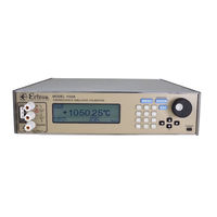
Ectron 1140A Instruction Manual (136 pages)
Thermocouple simulator-calibrator
Brand:
Ectron
| Category:
Test Equipment
| Size: 3.26 MB
Table of Contents
Table of Contents
3
List of Tables
6
List of Figures
7
Section I, Description
9
General
9
Changes from Previous Versions
10
About this Manual
10
Section II, Specifications
11
General
11
Source Mode
11
Thermocouple Output Mode
11
Voltage Output Mode
12
Meter Mode
12
Supported Standards
12
General Instrument Specifications
12
Thermocouple-Accuracy Tables
13
Table 2-1: Type B Thermocouple (°C)
14
Table 2-2: Type B Thermocouple (°F)
14
Table 2-3: Type C Thermocouple (°C)
14
Table 2-4: Type C Thermocouple (°F)
14
Table 2-5: Type D Thermocouple (°C)
15
Table 2-6: Type D Thermocouple (°F)
15
Table 2-7: Type E Thermocouple (°C)
15
Table 2-8: Type E Thermocouple (°F)
15
Table 2-10: Type G Thermocouple (°F)
16
Table 2-11: Type J Thermocouple (°C)
16
Table 2-12: Type J Thermocouple (°F)
16
Table 2-9: Type G Thermocouple (°C)
16
Table 2-13: Type K Thermocouple (°C)
17
Table 2-14: Type K Thermocouple (°F)
17
Table 2-15: Type N Thermocouple (°C)
17
Table 2-16: Type N Thermocouple (°F)
17
Table 2-17: Type Platinel II Thermocouple (°C)
18
Table 2-18: Type Platinel II Thermocouple (°F)
18
Table 2-19: Type R Thermocouple (°C)
18
Table 2-20: Type R Thermocouple (°F)
18
Table 2-21: Type S Thermocouple (°C)
19
Table 2-22: Type S Thermocouple (°F)
19
Table 2-23: Type T Thermocouple (°C)
19
Table 2-24: Type T Thermocouple (°F)
19
Section III, Unpacking and Installation
21
Shipment Contents
21
Unpacking
21
Model 1140A Installation
21
Packing for Shipment
21
Section IV, Operation
23
General
23
Front-Panel Controls
23
Connections
23
Power
23
Figure 4-1: Front View of the Model 1140A
23
Menu Key
24
Enter Key (Operate/Standby)
24
Escape Key
24
Twelve-Key Keypad
24
Four Arrow Keys
25
Encoder (Large Knob)
25
Operating Screen Main Display
25
Control
25
Mode
26
Offset
26
Reference-Junction Temperature
26
Material
26
Thermocouple Type
26
Table 4-1: Thermocouple Types in the Model 1140A
27
Message Displays
28
Menus
30
Thermocouple Menu
30
Figure 4-2: Main Menu
30
Figure 4-3: Thermocouple Menu
30
Instrument Mode Menu
32
Figure 4-4: Instrument Mode Menu
32
Output Menu
33
Figure 4-5: Output Menu
33
Memory Menu
34
Figure 4-6: Memory Menu with no Saved Files
34
Figure 4-7: Memory Menu with Saved Files
34
Sequence Menu
36
Figure 4-8: Sequence Menu
36
Data Logging Menu and Downloading Data
38
Figure 4-9: Data Logging Menu
38
Display Menu
39
Figure 4-10: Display Menu
39
Remote Menu
40
Figure 4-11: Remote Menu
40
Figure 4-12: Web Browser Using the Ethernet Interface
42
Maintenance Menu
43
Figure 4-13: Maintenance Menu
43
Diagnostics Menu
44
Table 4-2: Default Settings
44
Figure 4-14: Diagnostics Menu
44
Section V, Applications
47
General
47
Functions
47
Source Mode
47
Meter Mode
47
Battery Operation
48
Connections
48
Thermocouple Connections
48
Temperature Variation
49
Considerations
49
Polarity of Thermocouple Wires
49
Shielding and the Guard Terminals
49
Grounding
50
And IPTS-68
50
Offset
50
Autozero
51
Low Output Impedance
51
Guard Bands
52
Section VI, Remote Operation
53
Figure 6-1: Remote Menu
53
General
53
Remote Menu
53
Changing the Active Interface
53
Setting the Interface Address (GPIB Only)
53
Activating and De-Activating Remote Control
53
Table 6-1: Remote Command Summary
54
Model 1140A Commands
55
Source-Mode Commands and Queries
55
Meter-Mode Query
56
Thermocouple Commands and Queries
56
Instrument Commands and Queries
58
Output Commands and Queries
60
System Commands and Queries
61
Table 6-2: Model 1140A Error Codes
62
Data Logging Queries
63
Model 1120 Remote Emulation Option
64
Background
64
Limitations
64
Model 1120 Remote Control Operation
66
Errors
66
Table 6-3: Model 1120 Remote Commands
66
Section VII, Theory of Operation
67
Operating Modes
67
Thermocouple Simulator (Alloy Output)
67
Figure 7-1: Model 1140A Block Diagram
67
Precision Voltage Source (Copper Output)
68
Thermocouple Meter (Alloy Input)
68
Precision Voltmeter (Copper Input)
68
Thermocouple Simulator (Copper Output)
68
Thermocouple Meter (Copper Input)
68
Precision Voltage Source (Alloy Output)
69
Precision Voltmeter (Alloy Input)
69
Thermocouple Offset
69
Hardware Implementation
70
Firmware
70
Front-Panel Assembly
70
Analog Assembly
70
Optional Battery
71
Figure 7-2: Source-Mode Operation Diagram
71
Figure 7-3: Meter-Mode Operation Diagram
71
Power-Supply Assembly
72
Section VIII, Troubleshooting
73
General
73
Potential Problems
73
Model 1140A will Not Power up
73
Front-Panel Problems
74
Figure 8-1: Charging Supply Barrier Strip (High Voltage Guard Removed)
74
Digital Assembly Problems
75
Analog Assembly Problems
75
Figure 8-2: Fuse on Analog Assembly
76
Section IX, Maintenance and Repair
77
Cleaning
77
Repair Procedures
77
Equipment Required
77
Orientation
78
Ribbon Cable Connections
78
Top Cover Removal
78
Figure 9-1: Model 1140A Overall View
78
Figure 9-2: Model 1140A Overall View with Top Cover Removed
79
Top Cover Installation
80
Battery Installation
80
Charging Supply Removal
80
Figure 9-3: Battery Assembly and Charging Supply (Voltage Guard Removed)
80
Charging Supply Installation
81
Figure 9-4: Underside of Left Rear Corner
81
Remote Interface Assembly Removal
82
Table 9-1: Charging Supply Barrier Strip Wires
82
Figure 9-5: Digital and Keypad Assemblies
82
Remote Interface Assembly Installation
83
Digital Assembly Removal
83
Digital Assembly Installation
84
Encoder Removal
84
Encoder Installation
84
Left Side Panel and Front-Panel Bar Removal
85
Left Side Panel and Front-Panel Bar Installation
85
Keypad Removal
85
Figure 9-6: Left Side Panel
85
Keypad Installation
86
Analog Assembly Removal
86
Figure 9-7: Analog Assembly
87
Figure 9-8: Binding Post Printed Circuit Board and TC Connector
87
Analog Assembly Installation
88
Figure 9-9: Front Left Rail with Side Panel Removed
88
Figure 9-10: Wire Connections on Binding Post Printed Circuit Board
88
Power-Supply Assembly Removal
89
Power-Supply Assembly Installation
90
Front-Panel Assembly Removal
90
Figure 9-11: Power Supply Assembly
90
Front-Panel Assembly Installation
91
Binding Post Removal
92
Binding Post Installation
92
Front-Panel Display Removal
93
Figure 9-12: Display Assembly Area
93
Front-Panel Display Installation
94
Section X, Alignment
95
General
95
Equipment Required
95
Preliminary
95
Voltage Alignment
96
DAC (Digital-To-Analog Converter) Bit Alignment
96
Divider Gain Alignment
96
Source-Mode Alignment
96
Meter-Mode Zero Alignment
96
LSB (Least-Significant Bit) Alignment
96
Meter-Mode Sensitivity Alignment
97
Terminal Alignment
97
Thermocouple Alloy Corrections
97
Section XI, Calibration Procedure
99
General
99
Required Equipment
99
Test Reports
99
Procedure
100
Preliminary Setup
100
Linear-Voltage-Tests Setup
100
Figure 11-1: Initial Operating Screen for Voltage Tests
100
Linear-Voltage Tests in Source Mode
101
Figure 11-2: Setup for Source Tests
101
Linear-Voltage Tests in Meter Mode
102
Figure 11-3: Setup for Meter Tests
102
Thermocouple Voltage Tests
103
Figure 11-4: Initial Operating Screen for Temperature Tests
103
Thermocouple Alloy Tests
104
Figure 11-5: Operating Screen for Thermocouple Alloy Tests
105
Figure 11-6: Setup for Alloy Test at Binding Posts
105
Output-Current Test
106
Figure 11-7: Setup for Alloy Test at Thermocouple Connector
106
Figure 11-8: Setup for Output-Current Test
106
Section XII, Parts List
109
Names of Manufacturers
109
Parts List for the Model 1140A
110
Options and Accessories
111
Parts List for the Calibration Kit
111
Appendix A, Calibration Test Reports
113
Thirty-Day Specifications, ITS-90
114
Six-Month Specifications, ITS-90
119
One-Year Specifications, ITS-90
124
Appendix B, Thermocouple Calibration
129
Procedure
129
General
129
Equipment Required
129
Figure B-1: Type E Thermocouple Calibration Setup
130
Advertisement
Advertisement
Related Products
Ectron Categories
Amplifier
Network Hardware
Media Converter
Test Equipment
More Ectron Manuals
Login
Sign In
OR
Sign in with Facebook
Sign in with Google
Upload manual
Upload from disk
Upload from URL