Table of Contents
Advertisement
Quick Links
The information in this manual is proprietary and may not be reproduced without written
permission from this company.
LIFE-SUPPORT POLICY: Ectron products are not authorized for use in life-support
devices or systems without the express, written approval of the President of Ectron
Corporation.
This manual applies to serial numbers 81000 and above.
Copyright May, 2017
Ectron Corporation
All Rights Reserved
INSTRUCTION MANUAL
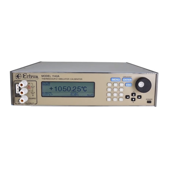
MODEL 1140A
THERMOCOUPLE
SIMULATOR-CALIBRATOR
Fax:
E-mail:
Web site:
Ectron Corporation
8159 Engineer Road
San Diego, CA 92111-1907
U.S.A.
858-278-0600
800-732-8159
858-278-0372
sales@ectron.com
www.ectron.com
Advertisement
Table of Contents

Summary of Contents for Ectron 1140A
- Page 1 The information in this manual is proprietary and may not be reproduced without written permission from this company. LIFE-SUPPORT POLICY: Ectron products are not authorized for use in life-support devices or systems without the express, written approval of the President of Ectron Corporation. This manual applies to serial numbers 81000 and above.
- Page 2 The obligation of Ectron under this warranty is limited solely to repairing or replacing, at its option, an instrument that in the sole opinion of Ectron proves to be defective within the scope of the warranty when returned to the factory or to an authorized service center. Transportation to the factory or service center is to be prepaid by the purchaser.
-
Page 3: Table Of Contents
Thermocouple Connections Section III, Unpacking and Installation Temperature Variation Considerations Shipment Contents Unpacking Polarity of Thermocouple Wires Shielding and the Guard Terminals Model 1140A Installation Grounding Packing for Shipment ITS-90 and IPTS-68 Offset Section IV, Operation Autozero General Low Output Impedance... - Page 4 Section VIII, Troubleshooting Divider Gain Alignment 10-2 General Source-mode Alignment 10-2 Potential Problems Meter-mode Zero Alignment 10-2 Model 1140A Will Not Power Up LSB (Least-significant Bit) Alignment 10-2 Front-panel Problems Meter-mode Sensitivity Alignment 10-3 Digital Assembly Problems Terminal Alignment 10-3...
- Page 5 Table of Contents Options and Accessories 12-3 Appendix B, Thermocouple Calibration Parts List for the Calibration Kit Procedure (114-519-01) 12-3 General Equipment Required Procedure Appendix A, Calibration Test Reports Thirty-day Specifications, ITS-90 Index Index 1 Six-month Specifications, ITS-90 One-year Specifications, ITS-90 A-12...
-
Page 6: List Of Tables
Table 2-21: Type S Thermocouple (°C) Table 2-22: Type S Thermocouple (°F) Table 2-23: Type T Thermocouple (°C) Table 2-24: Type T Thermocouple (°F) Table 4-1: Thermocouple Types in the Model 1140A Table 4-2: Default Settings 4-22 Table 6-1: Remote Command Summary... -
Page 7: List Of Figures
Figure 8-1: Charging Supply Barrier Strip (High Voltage Guard Removed) Figure 8-2: Fuse on Analog Assembly Figure 9-1: Model 1140A Overall View Figure 9-2: Model 1140A Overall View with Top Cover Removed Figure 9-3: Battery Assembly and Charging Supply (Voltage Guard Removed) Figure 9-4: Underside of Left Rear Corner... - Page 8 Table of Contents This page intentionally left blank.
-
Page 9: Section I, Description
The Model 1140A has the potential to simulate and measure a number of different thermocouple types. This allows the unit to simulate outputs of thermocouples to various international specifications including DIN, JIS, etc. -
Page 10: Changes From Previous Versions
Description A group of up to 31 setups can be arranged into a test sequence, and the Model 1140A can be commanded to step through the setups forward or backward. In this way frequently used tests may be easily repeated. The sequencing can even be done in a timed manner with the user establishing the time of each step. -
Page 11: Section Ii, Specifications
SECTION II SPECIFICATIONS GENERAL Unless otherwise noted, these specifications apply at 23°C ± 5°C, after a 30 minute warm-up period, for one year without calibration. Percentages and ratios are with respect to the output voltage. SOURCE MODE (Applies to both voltage and thermocouple outputs) −11 V dc to +11 V dc. -
Page 12: Voltage Output Mode
Less than three hours to fully recharge from a fully discharged state. CAUTION The battery pack used in the Model 1140A must be charged at least once every two months. If this is not done, the battery-pack voltage may decay... -
Page 13: Thermocouple-Accuracy Tables
Noise, 1 µV peak in a “0.1 Hz to 10 Hz” bandwidth. Accuracy, as listed on page for periods of 30 days, six months, and one year. Uncertainty limits (k = 2) of Ectron’s temperature measurement system, ±0.01°C. Conformity, ±0.4 µV. -
Page 14: Table 2-1: Type B Thermocouple (°C)
Specifications Table 2-1: Type B Thermocouple (°C) Error After: Temperature Range 30 Days Six Months One Year ±0.58 ±0.85 ±0.95 <350 ±0.41 ±0.60 ±0.74 <445 ±0.33 ±0.49 ±0.58 <580 ±0.26 ±0.38 ±0.45 <750 ±0.21 ±0.31 ±0.37 <1000 ±0.17 ±0.24 ±0.29 1000 1820 Table 2-2: Type B Thermocouple (°F) -
Page 15: Table 2-5: Type D Thermocouple (°C)
Specifications Table 2-5: Type D Thermocouple (°C) Error After: Temperature Range 30 Days Six Months One Year ±0.16 ±0.23 ±0.27 <100 ±0.12 ±0.17 ±0.20 <300 ±0.10 ±0.13 ±0.15 <1400 ±0.10 ±0.15 ±0.17 1400 <1650 ±0.12 ±0.16 ±0.20 1650 <1930 ±0.14 ±0.19 ±0.23 1930... -
Page 16: Table 2-9: Type G Thermocouple (°C)
Specifications Table 2-9: Type G Thermocouple (°C) Error After: Temperature Range 30 Days Six Months One Year ±1.10 ±1.30 ±1.50 <100 ±0.28 ±0.35 ±0.43 <300 ±0.14 ±0.19 ±0.24 <600 ±0.10 ±0.13 ±0.15 <1760 ±0.11 ±0.15 ±0.18 1760 <2030 ±0.13 ±0.17 ±0.21 2030 <2200... -
Page 17: Table 2-13: Type K Thermocouple (°C)
Specifications Table 2-13: Type K Thermocouple (°C) Error After: Temperature Range 30 Days Six Months One Year −270 ±1.50 ±1.90 ±2.20 <−255 −255 ±0.30 ±0.40 ±0.70 <−195 −195 ±0.10 ±0.11 ±0.12 <−115 −115 ±0.07 ±0.08 ±0.09 <−55 −55 ±0.06 ±0.07 ±0.07 <1000 ±0.06... -
Page 18: Table 2-17: Type Platinel Ii Thermocouple (°C)
Specifications Table 2-17: Type Platinel II Thermocouple (°C) Error After: Temperature Range 30 Days Six Months One Year ±0.07 ±0.08 ±0.10 <100 ±0.06 ±0.07 ±0.08 <925 ±0.07 ±0.08 ±0.10 <1200 ±0.08 ±0.09 ±0.11 1200 1395 Table 2-18: Type Platinel II Thermocouple (°F) Error After: Temperature Range 30 Days... -
Page 19: Table 2-21: Type S Thermocouple (°C)
Specifications Table 2-21: Type S Thermocouple (°C) Error After: Temperature Range 30 Days Six Months One Year −50 ±0.38 ±0.53 ±0.62 <−30 −30 ±0.32 ±0.47 ±0.56 <45 ±0.23 ±0.34 ±0.40 <105 ±0.20 ±0.30 ±0.33 <310 ±0.17 ±0.25 ±0.29 <615 ±0.15 ±0.22 ±0.26 1768.1... - Page 20 Specifications This page intentionally left blank. 2-10...
-
Page 21: Section Iii, Unpacking And Installation
MODEL 1140A INSTALLATION The battery (if any) in the Model 1140A is fully charged when shipped, but due to transit time or other delays it may have lost some charge by the time of first use. To ensure a full battery charge, plug the unit into ac power for three hours prior to running it on battery power. - Page 22 Unpacking and Installation This page intentionally left blank.
-
Page 23: Section Iv, Operation
(local control) or controlled over one of several interfaces (remote control) offered by Ectron, two of which can be installed at any one time with either being active at one time. Remote control is discussed in Section In this manual, controls are indicated by bold, capitalized text (for example, ENCODER). -
Page 24: Menu Key
Operation By default if the Model 1140A is in source mode and the Model 1120 Remote Emulation option is not enabled, when power is turned on the unit will be in standby mode as indicated by the blinking annunciator in the lower right corner of the display. In standby, the output terminals are disconnected from the voltage source within the instrument. -
Page 25: Four Arrow Keys
MEMORY MENU, pressing the ENCODER appends a character to the file name. OPERATING SCREEN MAIN DISPLAY About 15–20 seconds after powering on the Model 1140A, the operating screen will appear, displaying the current status and main settings of the unit. -
Page 26: Mode
The Model 1140A operates in two modes: source and measure. In the source mode, the Model 1140A produces a voltage output; in the measure mode, it accepts a voltage input. The voltage is either in volts, millivolts, or in temperature (the emf equivalent for the type thermocouple that is active). -
Page 27: Table 4-1: Thermocouple Types In The Model 1140A
Operation Table 4-1: Thermocouple Types in the Model 1140A Type* Positive Wire Negative Wire Temperature Range 250°C to 1820°C B-MN175 482°F to 3308°F 70% Pt – 30% Rh Alloy 94% Pt – 6% Rh Alloy [B-MN125] 523.15 K to 2093.15 K 22.33°R to 3767.67°R... -
Page 28: Message Displays
Message Displays Standby By default if the Model 1140A is in source mode, when power is turned on the unit will be in standby mode as indicated by the blinking annunciator in the lower right corner of the display. In standby, the output terminals are disconnected from the voltage source within the instrument. - Page 29 These errors may occur during alignment. The alignment will be aborted if any appear: NONE, A/D IS ALWAYS READY, SELF-ALIGNMENT TIMEOUT, INVALID PRE-ALIGN MODE, and INVALID POST-ALIGN MODE. To complete an alignment, the Model 1140A must be repaired. The unit will retain the previous alignment data.
-
Page 30: Menus
Operation removes the board, and power is then applied. In this instance, the error would be: CAN’T FIND GPIB OPTION BOARD. MENUS From the operating screen, pressing MENU will take the user to the MAIN MENU. If the cursor is active, pressing MENU has no effect. - Page 31 It is advisable to select the thermocouple-offset units before entering this value because the Model 1140A converts the temperature offset to match the units. For example, if the user sets the OFFSET to 1.0 when the UNITS are set to CELSIUS and then changes the units to FAHRENHEIT, the thermocouple offset displayed will convert automatically from 1.0°C to +1.8°F, which of course is...
-
Page 32: Instrument Mode Menu
Select SOURCE for the Model 1140A to act as a source; that is, to provide a simulated temperature out or provide a linear voltage output. Select METER for the Model 1140A to act as a meter to measure either linear voltage or the voltage input of a thermocouple. -
Page 33: Output Menu
Wire Material If the wire connections to the Model 1140A are copper, select COPPER; if thermocouple wire, ALLOY. Terminals Select the appropriate input connectors depending on the wire being used. Both copper and alloy can be connected to either input. -
Page 34: Memory Menu
For example if a meter being used has a known offset at 0 V, that offset in the opposite polarity should be entered so that in the source mode, the meter being calibrated will read correctly, and in the meter mode, the Model 1140A will correctly display the temperature or voltage of the thermocouple junction being measured. - Page 35 To enter more files, press MENU (or ESC twice) to return to the operating screen, make the desired changes (make sure to press ENTER so that the Model 1140A knows that the screen has been permanently updated as indicated by the lack of the blinking cursor) and again press MENU, then MEMORY.
-
Page 36: Sequence Menu
Operation Deleting a File To delete a file, press MENU, select MEMORY, and then DELETE. Next select the file name to be deleted and press ENTER. Prior to pressing ENTER, the user can cancel this operation by pressing ESC. After ENTER has been pressed, thus deleting the file, the next file in the “stack” becomes the working file. - Page 37 Stepping can either be timed or manual. If TIMED is selected, any valid time from 0.3 seconds to 99 hours: 59 minutes: 59.9 seconds can be set. This sets the time that the Model 1140A is set to each file in the sequence. For example, if the user wants to set up a sequence of 0°C to 100°C in 10°C increments and each sequence step is to last 20 seconds, the time should be set to...
-
Page 38: Data Logging Menu And Downloading Data
Data Logging Menu and Downloading Data In the METER mode, the Model 1140A has the capability to log, store, display, and download 10,000 data points, each of which contains a date, time, and the data itself. By going to the DATA LOGGING MENU, the user can set the time interval between data points and start logging data. -
Page 39: Display Menu
When the logging interval has been set, upon pressing ENTER the user will be asked to confirm that old data can be overwritten. Answer NO to return to the DATA LOGGING MENU without overwriting existing data. Answer YES, and the Model 1140A will begin logging data. One to 10,000 data points can be captured. -
Page 40: Remote Menu
Section VI for Remote Operation) The Model 1140A can have up to three interface cards installed at any one time, including the built-in USB. The REMOTE MENU tells the user what interfaces, if any, are installed and which one is active; and it allows the user to set the instrument’s remote address. - Page 41 IP ADDRESS, NETMASK, GATEWAY, and NAMESERVER are set by a DHCP server on the network. When DHCP is enabled, the user simply may give the Model 1140A a HOST NAME, which can be blank, and the TELNET PORT number.
-
Page 42: Figure 4-12: Web Browser Using The Ethernet Interface
When DHCP is DISABLED, the user must enter additional settings: IP ADDRESS, NETMASK, GATEWAY, and NAMESERVER. These settings should be obtained from the system administrator for the network in which the Model 1140A is connected. To enter them, highlight the desired number, press ENTER, key in the number, and again press ENTER. -
Page 43: Maintenance Menu
X, Alignment. Power-on Standby Mode This option controls whether the Model 1140A will be in standby mode when first turned on. The default setting is ON. If changed to OFF, the instrument will not enter standby mode on power-up. In either case, the OPR/STBY (ENTER) key still toggles standby off or on. -
Page 44: Diagnostics Menu
Operation Table 4-2: Default Settings Parameter Setting Thermocouple type / Output K-MN175* / 0.00°C Thermocouple offset units System units Thermocouple offset 0.00°C Reference-junction-temperature units System units Reference-junction temperature 0.00°C Instrument mode Source Output mode Temperature System temperature units Celsius (°C) System voltage units Volts (V) Temperature resolution limit... - Page 45 Operation About Select ABOUT to display the versions for the FIRMWARE and the COMPILER, the compile date for the firmware, and the serial number of the unit. 4-23...
- Page 46 Operation This page intentionally left blank. 4-24...
-
Page 47: Section V, Applications
The following instrument modes are available selected either by front panel or by remote control: Source Mode With the output mode set to TEMPERATURE, the Model 1140A becomes a precision thermo- couple simulator with six digits of display and resolution to 0.01 degrees. -
Page 48: Battery Operation
Normal performance can be obtained from the battery over the full temperature range of this instrument: 0°C to 50°C. For details of the battery-related messages that may appear in the display of the Model 1140A, Message Displays... -
Page 49: Temperature Variation
Applications Temperature Variation There are two primary sources of these errors: handling the thermocouple wires or the mini- connector and air flowing past the terminals. Typically these errors are well under 0.1°C although some conditions can increase these errors, and precautions must be taken to maintain the high accuracy of the instrument. -
Page 50: Grounding
The available range of offset is ±5°C for all thermocouple types or ±11.000 V dc for dc voltages. The thermocouple offset, accessible through the THERMOCOUPLE → THERMOCOUPLE OFFSET menu, is intended to be an offset at the temperature of the Model 1140A terminals, and is not an offset at the simulated (or measured) temperature. -
Page 51: Autozero
Thus, if the calibrated thermocouple’s output was less than the standard emf for that type, the correction applied would need to be positive. On the Model 1140A, a positive value would be entered in the THERMOCOUPLE OFFSET menu. -
Page 52: Guard Bands
(Seebeck effect) is most difficult since testing these instruments requires a highly accurate and stable TC simulator. Because the Model 1140A offers a new level of TC simulation accuracy, guard banding can be reduced giving more assurance that the device-under-test is meeting its specification. For example, if a data system is using Type S thermocouple material, and a test point is required at 1500°C, the nominal TC output is 15,581.67 µV and the Seebeck coefficient (emf change per... -
Page 53: Section Vi, Remote Operation
SECTION VI REMOTE OPERATION GENERAL The Model 1140A can be controlled remotely via one of the available interfaces: USB, GPIB, Ethernet, and RS-232. Three remote interfaces can be installed at any one time with any one of them being active. -
Page 54: Table 6-1: Remote Command Summary
If any front-panel key is pressed while in remote mode, a warning is displayed and the operator asked whether to return to local mode. Returning to local mode allows front-panel control. However, receipt of any remote command will again place the Model 1140A in remote mode. Table 6-1: Remote Command Summary... -
Page 55: Model 1140A Commands
Because the Model 1140A gives priority to remote control over front-panel control, continuous or nearly continuous remote commands will essentially lock out the front panel. Therefore, the remote command stream must be stopped before the Model 1140A can be controlled from the front panel. -
Page 56: Meter-Mode Query
Example: :SOUR:VOLT:VAL? returns the output value, e.g. +1.456000V. Query the Overload Status :OUTPut:OVERload? If there is an overload, the Model 1140A returns a 1; if not, a 0. Example: :OUTP:OVER? will return 0 for no overload. Change Standby Status :OUTPut:STANdby {Standby Status} {Standby Status} must be OFF or ON. - Page 57 Remote Operation Setting either the thermocouple type or the simulation temperature first will usually resolve the issue, but not always. There are pairs of thermocouple types for which neither the new nor the old simulation temperature will be within range of both new and old thermocouple types.
-
Page 58: Instrument Commands And Queries
Remote Operation Example: :INST:THER:OFFS:VAL? could return +1.45C. Set the Reference-junction Temperature Unit of Measure :UNIT:REFJunction {Unit of measure} {Unit of measure} must be C, F, R, K, or SYSTEM. If SYSTEM is entered, reference- junction unit of measure will be the present system unit of measure. When the reference- junction temperature unit of measure is changed, the reference-junction temperature value may change: e.g. - Page 59 Remote Operation Set the Output Entry Mode :INSTrument:MODE:ENTRy {Mode} {Mode} must be VOLT (for voltage) or TEMP (for temperature). Example: :INST:MODE:ENTR TEMP sets the instrument entry mode to temperature. Query the Entry Mode :INSTrument:MODE:ENTRy? Returns either VOLT (for voltage) or TEMP (for temperature). Example: :INST:MODE:ENTR? returns VOLT.
-
Page 60: Output Commands And Queries
Valid inputs for {Material} are ALLOY or COPPER. Example: :INST:MAT ALLOY sets the unit to work with alloy connections. Query the Material of the Wires with which the Model 1140A is set to operate :INSTrument:MATerial? Example: :INST:MAT? would return either COPPER or ALLOY. -
Page 61: System Commands And Queries
System Commands and Queries Reset the Model 1140A to Default Values :STATus:PRESet The following command will reset the Model 1140A to its default values. Not affected are screen contrast and brightness, contents of the MEMORY MENU and the SEQUENCE MENU, and calibration parameters. -
Page 62: Table 6-2: Model 1140A Error Codes
105 Voltage out of range The voltage being programmed is out of range. 106 Output overload The Model 1140A is incapable of supplying the programmed output. 107 Thermocouple invalid for The thermocouple type commanded is not available in the temperature scale current temperature scale. -
Page 63: Data Logging Queries
Remote Operation Query the First Error Code in the Queue :SYSTem:ERRor:CODE? This command pops the oldest error out of the queue and returns its numeric code. Refer to Table 6-2 for error codes. Example: :SYST:ERR:CODE? might return −100. Query All Error Codes in the Queue :SYSTem:ERRor:CODE:ALL? Example: :SYST:ERR:CODE:ALL? might return: −100 Query the Count of Errors in the Queue :SYSTem:ERRor:COUNt? -
Page 64: Model 1120 Remote Emulation Option
Packet Delimiter The Models 1120 and 1140A both detect the EOI GPIB bus flag as a packet delimiter. In addition, the Model 1140A also treats carriage return and newline characters as packet delimiters. This is only significant if remotely editing output values over multiple packets (see below). - Page 65 METER MODE NOT ALLOWED IN 1120 EMULATION MODE PRESS ANY KEY TO CONTINUE If the Model 1140A is in the METER mode, and the user ENABLES the Model 1120 Remote Emulation mode, the Model 1140A will switch to SOURCE mode. Standby Mode When the Model 1120 Remote Emulation mode is enabled, standby mode is unavailable.
-
Page 66: Model 1120 Remote Control Operation
4.581MUZ would return 4.581 mV in copper mode. If an error is made in the command, the Model 1120 returns an Error Code. In the Model 1140A using Model 1120 Remote Emulation, when an incorrect command is sent the applicable Error Code is returned to the front panel between the annunciator 1120 MODE and the large value in the middle. -
Page 67: Section Vii, Theory Of Operation
(T) represents the theoretical emf that would be produced by a thermocouple of the selected type at temperature T. Thermocouple Simulator (Alloy Output) The general equation for the Model 1140A when it is simulating a thermocouple in the alloy mode is OUTPUT... -
Page 68: Precision Voltage Source (Copper Output)
Theory of Operation Precision Voltage Source (Copper Output) The general equation for the Model 1140A when it is used as a precision linear voltage source in the copper mode is OUTPUT SOURCE OFFSET where V is the voltage produced at the terminals, V... -
Page 69: Precision Voltage Source (Alloy Output)
Thermocouple Offset The thermocouple offset, accessible through the THERMOCOUPLE → THERMOCOUPLE OFFSET menu, is intended to be an offset at the temperature of the Model 1140A terminals, and is not an offset at the simulated (or measured) temperature. The offset applied is computed using the Seebeck coefficient for the current thermocouple type, at the temperature of the front-panel terminals in use. -
Page 70: Hardware Implementation
Theory of Operation HARDWARE IMPLEMENTATION Firmware All operations of the Model 1140A are controlled by firmware flashed onto the digital board. The firmware performs the following tasks: • Manages the user interface including the front-panel controls and display. • Monitors the temperature of the instrument and each front-panel terminal. -
Page 71: Optional Battery
Theory of Operation Figure 7-2: Source-mode Operation Diagram As can be seen in the figure, the DAC passes a fraction of the reference voltage to the output buffer and on to the instrument output. Firmware in the microprocessor decides what fraction of the voltage should be passed to the output, based on user settings, output terminal temperature, and the reference equations for the thermocouple type in use. -
Page 72: Power-Supply Assembly
BATT FLT or TEMP FLT is indicated on the display. If either of these fault conditions is indicated and the Model 1140A is not at room temperature, the unit should be returned to room temperature and ac power momentarily interrupted to see if the fault recurs. -
Page 73: Section Viii, Troubleshooting
TROUBLESHOOTING GENERAL Troubleshooting the Model 1140A, except for a few components, is limited to the assembly level. Because it employs surface-mount technology, special equipment, often not available, is required to troubleshoot to the component level. Additionally, there are many components that if changed would necessitate special testing done only at the factory. -
Page 74: Front-Panel Problems
Troubleshooting Solution: Ensure that the power cord is plugged into the unit and into an adequate power source as given in Section II under Operation. Loosen the screw that holds the ac voltage guard to the charging supply, and remove the guard. Using the DMM, check the ac voltage to the charging power supply at its terminals (see Figure 8-1). -
Page 75: Digital Assembly Problems
Fault: Unit operates in neither meter nor source mode Solution: Check the dc voltage at the charging supply terminals as described above. If no problem is found, the power supply or the analog assembly may require repair. Contact Ectron for further instructions. -
Page 76: Figure 8-2: Fuse On Analog Assembly
Troubleshooting Fault: Unit operates in meter mode but not in source Solution: Replace the fuse on the analog assembly (see Figure 8-2). If the problem persists, the analog assembly may require repair. Contact Ectron for further instructions. Front Input-protection fuse... -
Page 77: Section Ix, Maintenance And Repair
MAINTENANCE AND REPAIR CLEANING In general, a damp cloth is all that is needed for cleaning the Model 1140A. If using a chemical cleaner, avoid any alcohol-based products. When cleaning the front-panel LCD display, use a soft cloth to prevent scratching. -
Page 78: Orientation
Maintenance and Repair Orientation Throughout this section, any references to the “left” or “right” side of the Model 1140A are given from the point of view of looking at the front of the unit. Refer to Figure for an overview. -
Page 79: Figure 9-2: Model 1140A Overall View With Top Cover Removed
Plug the four-pin battery connector into the power-supply assembly. See Figure 9-2. Place the top cover on top of the Model 1140A with the flange toward the front. Using a 3/16″ slot screwdriver, install the four captive screws on the top cover. -
Page 80: Top Cover Installation
Refer to Figure for the locations of the components mentioned in this procedure. Set the battery in the Model 1140A next to the charging supply. Be sure the battery wires are at the top and toward the power-supply assembly. Place the battery hold-down bracket over the battery and set it down over the two studs. -
Page 81: Charging Supply Installation
While supporting the charging supply and its mounting bracket, use a #2 Phillips screwdriver from the underside of the Model 1140A to remove the three flat head screws that hold the charging supply mounting bracket to the bottom plate. See Figure 9-4. -
Page 82: Remote Interface Assembly Removal
Maintenance and Repair Table 9-1: Charging Supply Barrier Strip Wires Function Wire Color −V or COM Black Ground Green/Yellow Brown Blue Remote Interface Assembly Removal Follow Procedure Top Cover Removal. Unplug the appropriate remote interface ribbon cable from the digital assembly. See Figure 9-5. -
Page 83: Remote Interface Assembly Installation
Using a #2 Phillips screwdriver from the underside of the unit, remove the two flat head screws that hold the remote interface bracket to the bottom plate. See Figure 9-4. Remove the remote interface connector assembly from the Model 1140A. Remote Interface Assembly Installation Position the remote interface bracket into one of the two locations at the back of the unit, labeled Optional Interface 1 and Optional Interface 2 on the rear panel. -
Page 84: Digital Assembly Installation
Install the ENCODER from the rear of the front panel, and orient it so that the connector is toward the top of the Model 1140A. See Figure 9-5. Install the nut on the threads of the ENCODER. Take care not to cross-thread the nut as the threads of the ENCODER are plastic. -
Page 85: Left Side Panel And Front-Panel Bar Removal
Place the Model 1140A on its right side. Gently pull the left side panel away from the Model 1140A. The front panel bars are secured to the side panels by 1/16″ dowel pins. Be careful not to lose these pins. -
Page 86: Keypad Installation
Maintenance and Repair Remove the keypad connector from the rear of the keypad assembly. See Figure 9-5. Remove the encoder connector from the rear of the keypad assembly. See Figure 9-5. Unsolder the black and red twisted wires (marked A and K) from the keypad board. Remove the six mounting nuts and lock washers retaining the keypad board using a 3/16″... -
Page 87: Figure 9-7: Analog Assembly
Maintenance and Repair Binding post temperature sensor wires ← Front Binding post PC board Figure 9-7: Analog Assembly Front TC connector between two mounting blocks Binding post Binding post PC board temperature sensor wires Figure 9-8: Binding Post Printed Circuit Board and TC Connector Unsolder the two pairs of black and red twisted wires from the binding post printed circuit board. -
Page 88: Analog Assembly Installation
If the analog assembly is to be stored or shipped, fasten the analog assembly and TC connector assembly together with a shipping bracket provided by Ectron. Use the screws supplied with the bracket, and tighten the screws to 10 in-lb torque. -
Page 89: Power-Supply Assembly Removal
Maintenance and Repair Solder the black and red twisted wires from the analog assembly to the binding post printed circuit board. The red wire goes into the top open hole on the side toward the display, the black wire into the open hole directly below the red wire. See Figure 9-10. -
Page 90: Power-Supply Assembly Installation
Figure 9-11: Power Supply Assembly Power-supply Assembly Installation Hold the power-supply assembly over the Model 1140A and insert the power switch extension shaft through the cutout in the front panel. Lower the power-supply assembly into the chassis in front of the ac line filter. -
Page 91: Front-Panel Assembly Installation
Carefully remove the front panel. Front-panel Assembly Installation Position the front panel in front of the Model 1140A. Solder the two green guard wires onto the holes near the bottom of the binding post printed circuit board. Either wire may go in either hole. -
Page 92: Binding Post Removal
Binding Post Installation Ensure that the front-panel assembly is loose from the Model 1140A. If not, remove the front-panel assembly using Procedure 21. Install the binding post with the undrilled stud into the lowest post hole in the panel. -
Page 93: Front-Panel Display Removal
Install the binding post printed circuit board on the rear of the binding posts. Position it such that the word ECTRON on the printed circuit board is readable from the rear of the panel, and is located between the bottom two binding posts. -
Page 94: Front-Panel Display Installation
Maintenance and Repair Remove the four nylon nuts holding the LCD display assembly in place, located near the four corners of the board, using a 5/16″ socket. CAUTION Take care not to damage the front-panel overlay or the display when separating them. Remove the display assembly by carefully pulling it away from the front-panel overlay. -
Page 95: Section X, Alignment
0.4″ (10 mm). PRELIMINARY Turn the power to the Model 1140A off, set the alignment switch (recessed in a square hole in the bottom cover just to the rear of the KEYPAD) to the right to enable ALIGNMENT, and turn the Model 1140A on. -
Page 96: Voltage Alignment
ENTER (unless two voltage standards are used, this will be same number but with negative polarity as that number used above). Again, when this alignment step is completed, the user is directed to remove all connections to the Model 1140A and to press any key to continue. -
Page 97: Meter-Mode Sensitivity Alignment
Alignment Meter-mode Sensitivity Alignment As directed on the screen, connect the shorting bar to the Model 1140A binding posts and press ENTER to continue. When the alignment step is complete, remove the shorting bar and press any key to continue. - Page 98 Alignment Convert the Model 1140A’s error from microvolts to degrees Celsius. For a Type E thermocouple, the conversion is: Error in °C = (error in µV) × 0.0164°C/µV. Negate the polarity of the error to produce the correction amount. For example, if the DMM reads 1.3 µV above the expected value, the correction is –0.021°C.
-
Page 99: Section Xi, Calibration Procedure
Model 1140A are restored to their defaults. This procedure should be followed in the order presented. Deviation from it may result in an incorrect setting that is not specifically addressed in this procedure but is addressed when RESET INSTRUMENT TO DEFAULT VALUES is performed. -
Page 100: Procedure
PROCEDURE Preliminary Setup Turn on the Model 1140A. Restore the Model 1140A to its default settings. Press MENU to go the MAIN MENU. The cursor must be absent. If the cursor is present, press ESC and then MENU. Scroll to MAINTENANCE and press ENTER to go the MAINTENANCE MENU. -
Page 101: Linear-Voltage Tests In Source Mode
Figure 11-2: Setup for Source Tests Linear-voltage Tests in Source Mode Connection the Model 1140A to the DMM using the low-thermal cable as is shown in Figure 11-2. For each of the linear-voltage tests on the test report that has a unit of volts: Set the Model 1140A to the specified voltage using the ARROW KEYS, ENCODER, or KEYPAD. -
Page 102: Linear-Voltage Tests In Meter Mode
Scroll to INSTRUMENT MODE and press ENTER. Select METER and press ENTER. Press MENU to return to the operating screen. Set the Datron Model 4708 for dc volts and connect it to the Model 1140A as is shown in Figure 11-3 using low-thermal leads. -
Page 103: Thermocouple Voltage Tests
Reconnect the Model 4708 to the Model 1140A. Continue as in Step 3, but measuring the test points that are given in volts. Disconnect the Model 1140A from the Datron Model 4708. Figure 11-4: Initial Operating Screen for Temperature Tests Thermocouple Voltage Tests Connect the equipment as is shown in Figure 11-2. -
Page 104: Thermocouple Alloy Tests
The operating screen should be as is shown in Figure 11-4. For each of the Celsius readings of thermocouple type B-MN175: Program the Model 1140A to the temperature indicated in the test report. Record each reading on the DMM. Ensure that it is within tolerance. -
Page 105: Figure 11-5: Operating Screen For Thermocouple Alloy Tests
Select BINDING POSTS and press ENTER. Press MENU to return to the operating screen. The Model 1140A operating screen should be as is shown in Figure 11-5. Observing proper polarity, connect the equipment as is shown in Figure 11-6. Ensure that the cold junction of the thermocouple is fully immersed in the ice bath. -
Page 106: Output-Current Test
Calibration Procedure Figure 11-7: Setup for Alloy Test at Thermocouple Connector Connect the Type E thermocouple to the Model 1140A thermocouple connector, inserting the bare wire ends all the way into the holes. Optionally, cover the terminals to shield them from air flow. - Page 107 Select BINDING POSTS and press ENTER. Press MENU to return to the operating screen. Set the Model 1140A for +1 V dc output using the ENCODER, the ARROW KEYS, or KEYPAD. The DMM must read between +50 mA dc and +100 mA dc. Record the reading and ensure that it is within specification.
- Page 108 Calibration Procedure This page intentionally left blank. 11-10...
-
Page 109: Section Xii, Parts List
LAMBDA 00532 LITTELFUSE INC. 00583 MICRO PLASTICS, INC. 00672 INTERPOWER CORPORATION 00759 ROGAN 00763 SAMTEC 00861 SUPERIOR ELECTRIC CO. 01164 PENN ENGINEERING 01176 VOLEX-BELDEN 01198 COMMERCIALLY AVAILABLE 01230 ECTRON CORPORATION 01298 MCMASTER CARR 01388 E-SWITCH 01418 CABLEWHOLESALE.COM 01434 STARTECH.COM 12-1... -
Page 110: Parts List For The Model 1140A
Parts List PARTS LIST FOR THE MODEL 1140A REFERENCE DESIGNATOR DESCRIPTION MANUFACTURER’S P/N ECTRON P/N ASSEMBLY, ANALOG 01230 114-501-01 ASSEMBLY, DIGITAL 01230 114-521-01 ASSEMBLY, POWER SUPPLY 01230 114-515-01 ASSEMBLY, KEY PAD PCB 01230 114-502-01 ASSEMBLY, FRONT PANEL 01230 114-506-05 KIT, FILLER PANEL... -
Page 111: Options And Accessories
Parts List REFERENCE DESIGNATOR DESCRIPTION MANUFACTURER’S P/N ECTRON P/N TO MOUNT POWER-SUPPLY BOARD SCREW, PHILLIPS 01198 6-32 X 5/16 PAN HEAD STAINLESS E-130500-0 TO MOUNT POWER-SUPPLY BOARD WASHER, SPLIT LOCK 01198 #6 X .031 X .250 STAINLESS E-306034-0 TO HOLD PCB AND KEYPAD TO PANEL... - Page 112 Parts List This page intentionally left blank. 12-4...
-
Page 113: Appendix A, Calibration Test Reports
APPENDIX A CALIBRATION TEST REPORTS Sample calibration test reports for the Model 1140A are provided on the following pages for testing within 30 days, six months, or one year from the time of calibration. The Expanded Measurement Uncertainty column is blank for the user to calculate the expanded uncertainty,... -
Page 114: Thirty-Day Specifications, Its-90
Calibration Test Reports Ectron Model 1140A Calibration Test Report Thirty-day Specifications, ITS-90 Customer Date Address Serial Number Report Number Other Identifier Procedure Model 1140A Instruction Manual, Section XI Linear-voltage Tests Expanded Source Meter Measurement Voltage Reading Reading Tolerance Uncertainty 11.00000 V 10.999779 V to... - Page 115 Calibration Test Reports Ectron Model 1140A Calibration Test Report Thirty-day Specifications, ITS-90 Report Number Thermocouple-voltage Tests (Source Mode) Expanded Measurement Type Temperature Reading Tolerance Uncertainty B-MN175 400°C 786.5 µV µV 785.1 µV to 787.9 µV B-MN175 800°C 3153.6 µV µV 3152.1 µV to...
- Page 116 Calibration Test Reports Ectron Model 1140A Calibration Test Report Thirty-day Specifications, ITS-90 Report Number Thermocouple-voltage Tests (Source Mode), continued Expanded Measurement Type Temperature Reading Tolerance Uncertainty 500°C 4844.8 µV µV 4843.3 µV to 4846.3 µV 1200°C 18613.7 µV µV 18611.9 µV to 18615.5 µV 2250°C 37731.6 µV...
- Page 117 Calibration Test Reports Ectron Model 1140A Calibration Test Report Thirty-day Specifications, ITS-90 Report Number Thermocouple-voltage Tests (Source Mode), continued Expanded Measurement Type Temperature Reading Tolerance Uncertainty PL II 50°C 1574.7 µV µV 1573.3 µV to 1576.1 µV PL II 700°C 29100.8 µV µV...
- Page 118 Calibration Test Reports Ectron Model 1140A Calibration Test Report Thirty-day Specifications, ITS-90 Report Number Thermocouple-alloy Tests Expanded Measurement Type E-MN175 Connected to Reading Tolerance Uncertainty −2.9 µV to 2.9 µV Binding Posts µ V −2.9 µV to 2.9 µV Thermocouple Connector µ...
-
Page 119: Six-Month Specifications, Its-90
Calibration Test Reports Ectron Model 1140A Calibration Test Report Six-month Specifications, ITS-90 Customer Date Address Serial Number Report Number Other Identifier Procedure Model 1140A Instruction Manual, Section XI Linear-voltage Tests Expanded Source Meter Measurement Voltage Reading Reading Tolerance Uncertainty 11.00000 V 10.999723 V to... - Page 120 Calibration Test Reports Ectron Model 1140A Calibration Test Report Six-month Specifications, ITS-90 Report Number Thermocouple-voltage Tests (Source Mode) Expanded Measurement Type Temperature Reading Tolerance Uncertainty B-MN175 400°C 786.5 µV µV 784.1 µV to 788.9 µV B-MN175 800°C 3153.6 µV µV 3151.1 µV to...
- Page 121 Calibration Test Reports Ectron Model 1140A Calibration Test Report Six-month Specifications, ITS-90 Report Number Thermocouple-voltage Tests (Source Mode), continued Expanded Measurement Type Temperature Reading Tolerance Uncertainty 500°C 4844.8 µV µV 4842.3 µV to 4847.3 µV 1200°C 18613.7 µV µV 18610.8 µV to 18616.6 µV 2250°C 37731.6 µV...
- Page 122 Calibration Test Reports Ectron Model 1140A Calibration Test Report Six-month Specifications, ITS-90 Report Number Thermocouple-voltage Tests (Source Mode), continued Expanded Measurement Type Temperature Reading Tolerance Uncertainty PL II 50°C 1574.7 µV µV 1572.3 µV to 1577.1 µV PL II 700°C 29100.8 µV µV...
- Page 123 Calibration Test Reports Ectron Model 1140A Calibration Test Report Six-month Specifications, ITS-90 Report Number Thermocouple-alloy Tests Expanded Measurement Type E-MN175 Connected to Reading Tolerance Uncertainty −3.5 µV to 3.5 µV Binding Posts µ V −3.5 µV to 3.5 µV Thermocouple Connector µ...
-
Page 124: One-Year Specifications, Its-90
Calibration Test Reports Ectron Model 1140A Calibration Test Report One-year Specifications, ITS-90 Customer Date Address Serial Number Report Number Other Identifier Procedure Model 1140A Instruction Manual, Section XI Linear-voltage Tests Expanded Source Meter Measurement Voltage Reading Reading Tolerance Uncertainty 11.00000 V 10.999668 V to... - Page 125 Calibration Test Reports Ectron Model 1140A Calibration Test Report One-year Specifications, ITS-90 Report Number Thermocouple-voltage Tests (Source Mode) Expanded Measurement Type Temperature Reading Tolerance Uncertainty B-MN175 400°C 786.5 µV µV 783.6 µV to 789.4 µV B-MN175 800°C 3153.6 µV µV 3150.6 µV to...
- Page 126 Calibration Test Reports Ectron Model 1140A Calibration Test Report One-year Specifications, ITS-90 Report Number Thermocouple-voltage Tests (Source Mode), continued Expanded Measurement Type Temperature Reading Tolerance Uncertainty 500°C 4844.8 µV µV 4841.8 µV to 4847.8 µV 1200°C 18613.7 µV µV 18610.2 µV to 18617.2 µV 2250°C 37731.6 µV...
- Page 127 Calibration Test Reports Ectron Model 1140A Calibration Test Report One-year Specifications, ITS-90 Report Number Thermocouple-voltage Tests (Source Mode), continued Expanded Measurement Type Temperature Reading Tolerance Uncertainty PL II 50°C 1574.7 µV µV 1571.8 µV to 1577.6 µV PL II 700°C 29100.8 µV µV...
- Page 128 Calibration Test Reports Ectron Model 1140A Calibration Test Report One-year Specifications, ITS-90 Report Number Thermocouple-alloy Tests Expanded Measurement Type E-MN175 Connected to Reading Tolerance Uncertainty −4.1 µV to 4.1 µV Binding Posts µ V −4.1 µV to 4.1 µV Thermocouple Connector µ...
-
Page 129: Appendix B, Thermocouple Calibration
Set the stirred bath to 26°C and allow it to stabilize. 5 This assumes a laboratory temperature of 23ºC during the alignment and calibration of the Model 1140A. If the laboratory temperature is different, the wire should be calibrated at 3ºC above the typical laboratory temperature. -
Page 130: Figure B-1: Type E Thermocouple Calibration Setup
Thermocouple Calibration Procedure Figure B-1: Type E Thermocouple Calibration Setup Mechanically fix the hot junction of the thermocouple under test at the midpoint of the sensing portion of the PRT using a suitable nonconductive tie. Ensure that any bare thermocouple wires do not touch the PRT sheath. Place the PRT and the attached thermocouple hot junction in the stirred bath and allow it to stabilize. - Page 131 INDEX Numeric Installation, Messages, see Messages. 1120 emulation, see Model 1120 Remote Operation, Emulation. Recharge, 1140A, description of, Removal, Binding posts Applications, Ac operation, Installation, 9-16 Specifications, Removal, 9-16 Ac power, troubleshooting, Selecting, 4-11 A/D subsystem errors, Button, power, Alignment,...
- Page 132 Index Downloading data, 4-17 Escape key, Menu, 4-16 Ethernet setup, 4-19 Setting the logging interval, 4-17 Starting, 4-17 Viewing logged data, 4-17 Files Viewing logged instrument setup, 4-17 Creating new, 4-13 Date, setting, 4-21 Deleting, 4-14 Dc operation, Opening, 4-13 Specifications, Renaming, 4-13...
- Page 133 Index Interference, shielding against, Remote, 4-18 Internal clock, troubleshooting, Sequence, 4-14 IPTS-68, Thermocouple, Selecting, 4-11 Messages, ITS-90, A/D subsystem, Selecting, 4-11 Alignment switch on, Test report, Autozero (AZ), 4-12, Batt flt, Batt OK, Charged, Keys, Charging, Arrow, Interface board errors, Enter, Low batt, Escape,...
- Page 134 Index Commands and queries, Downloading data via, 4-17 Noise, shielding against, Installation, Numeric keypad, Menu, 4-18 Operation, Removal, Offset, Renaming a file, 4-13 Applications, Repair, Copper voltage, 4-12 Analog assembly, 9-10 Thermocouple, Battery, Opening a file, 4-13 Binding posts, 9-16 Operate (vs.
- Page 135 Index Shipment contents, Thermocouple Source mode, Accuracy specifications, Selecting, 4-10 Calibration procedure, Specifications, Connector, 4-11, Specifications, Corrections, 10-3 General, Menu, Meter mode, Meter (alloy input), theory, Source mode, Meter (copper input), theory, Thermocouple accuracy, Offset, 4-4, Standby, 4-1, 4-6, 4-21 Simulator (alloy output), theory, Starting a sequence, 4-14...
- Page 136 Index Voltage Alignment, 10-2 Resolution limit, setting, 4-11 Offset, setting, 4-12 Output, selecting, 4-10 Source (alloy output), theory, Source (copper output), theory, Units, system, 4-10 Voltmeter Alloy input, theory, Copper input, theory, Wire material, setting, 4-11 Zeroing, see Autozero. Index 6...
Need help?
Do you have a question about the 1140A and is the answer not in the manual?
Questions and answers