Sign In
Upload
Manuals
Brands
Dickey-John Manuals
Control Systems
IntelliAg
User Manuals: Dickey-John IntelliAg Control System
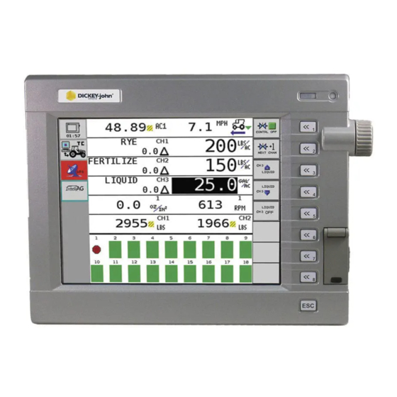
Manuals and User Guides for Dickey-John IntelliAg Control System. We have
2
Dickey-John IntelliAg Control System manuals available for free PDF download: Operator's Manual, Manual
Dickey-John IntelliAg Operator's Manual (175 pages)
Planter Drill Control system
Brand:
Dickey-John
| Category:
Control Systems
| Size: 12 MB
Table of Contents
Table of Contents
1
Safety Notices
9
System Overview
11
Virtual Terminal (VT)
11
Master Switch
12
Working Set Master (WSMT) Module (Planter Drill Control)
12
Working Set Member (WSMB) Module (Optional)
13
Implement Lift Switch (Optional)
13
CAN Terminators
13
System Requirements
15
Performance Features
15
Compatibility
16
Installation
17
Virtual Terminal
17
Master Switch
17
Working Set Master (WSMT) Module
18
Working Set Member (WSMB) Module
20
Cab Harness Connections
23
Sensor Installation
29
Seed Sensors
29
Hopper Level Sensors
31
Rpm/Fan Sensors
31
Air Pressure Sensors
31
System Modes
33
User Level Access
33
Operate Mode
33
Available Buttons in Operate Mode
34
Setup/Configuration Mode
36
Available Buttons in Setup Mode
36
Planter Fill Disk
36
Row Monitor Setup
36
Control Setup
36
Speed Set
37
Diagnostics
37
Alarm Log
37
System Accumulators
37
Module Configuration
37
Screen Configuration
37
Planter Output Module (POM) Configuration (Optional)
37
Configuration
37
User Levels
39
User Level 1 Operator (Basic View)
39
Change Operator Level to Oem/Dealer Level
40
System Configuration
43
Control Setup Overview
43
Material/Channel Setup Steps
43
Control Channel and Material Selection
45
Material Assignment (Matrl 1-16)
45
Material Setup
46
Create a Material Name
46
Type
47
Units
47
Preset Method Enabled
47
Preset Method Disabled
48
Material Setup Constants - Planter Control
49
Target Rate
49
Max Rate
49
Min Rate
49
Inc/Dec
49
Seeds Per Rev
50
Disc High Limit
50
Disc Low Limit
50
Prod Level Alarm
50
High and Low Population Alarm
50
Row Width
51
On/Off Pattern
51
Row Fail Rate
51
Material Setup Constants-Gran Seed and Gran Fertilizer Control
52
Target Rate
52
Max Rate
52
Min Rate
52
Inc/Dec
52
Density
53
Spreader Constant
53
High Shaft RPM
53
Prod Level Alarm
53
Seeds Per Pound
54
High and Low Population Alarm
54
Row Width
54
On/Off Pattern
55
Row Fail Rate
55
Material Setup Constants-Liquid Flow
56
Target Rate
56
Max Rate
56
Min Rate
56
Inc/Dec
56
Low Flow Limit
57
High Flow Limit
57
Product Level Alarm
57
Material Setup - Monitor Only
58
Type
58
Target Population
58
High and Low Population Alarms
58
Row Width
58
On/Off Pattern
59
Row Fail Rate
59
Material Setup Constants - RPM Control
60
Target Rate
60
Max Rate
60
Min Rate
60
Inc/Dec
60
Control Channel Setup
61
Planter Control Setup
62
Type
62
Material Name
62
Control Mode
62
Drive Type
63
Drive Frequency
63
Sensor Constant
63
Gear Ratio
63
Number (#) of Seed Rows
63
Channel Width
63
Precharge Time
63
Flush Enable
65
Valve Calibration - Planter Control
66
Fill Disk
67
Continuous Test
69
Test Ground Speed
69
Row
69
Test Target Pop
69
Test Seed Count
70
Rev Test
70
Test Ground Speed
71
Row
71
Test Target Pop
71
Test Seed Count
71
Remote Test Switch
71
Granular Seed and Granular Fert Setup
72
Valve Calibration - Gran Seed and Gran Fert
75
Fill Disk
76
Fill Disk for a Control Channel
76
Limit Output
78
Spreader Calibration- Gran Seed and Gran Fertilizer
79
Density
79
Spreader Constant
79
Target Meter RPM
80
Number (#) Meter Revs
80
Pulse Count
80
New Spreader Constant
80
Amount Dispensed
80
Shaft Turn
80
Liquid Flow Setup
81
Manual W/O Feedback
81
Valve Calibration - Liquid
84
Liquid Flow Calibration
86
RPM Control Setup
88
Type
88
Material Name
88
Manual W/O Feedback
88
Drive Type
89
Drive Frequency
89
Input Filter
89
Sensor Constant
89
Master Switch off
89
Ramp Up/Down
89
Disable Control on Control Failure Alarm
90
Valve Calibration - RPM Control
91
Module Configuration
93
Serial Number and Module Type
93
Module Address
94
Auto Sort
95
Auto Configuration
95
Auto Sort and Auto Config Examples
96
Row Assignment
100
Row Status/Row Width Setup
101
Row Width
101
Auto Update Width
101
Implement Width
102
On/Off Pattern
102
Blockage Pattern
103
Hopper Assignment
104
Hopper Set
105
Logic Level
105
Alarm Delay
106
Channel
106
Accessory Assignment
106
Of Pressure/Rpm Sensors
107
RPM Setup
107
High Alarm
107
Low Alarm
107
High Alarm Delay
108
Low Alarm Delay
108
RPM Constant
108
RPM Filter
108
Disable Control on Low Alarm
108
Pressure Sensor Setup
109
High Alarm
109
Low Alarm
109
High Alarm Delay
109
Low Alarm Delay
109
Pressure Filter
110
Row Monitor Setup
111
Material Name
111
High Alarm Delay
111
Low Alarm Delay
112
Population Adjust
112
Population Filter
112
Row Fail Rate
112
Ground Speed Setup
113
Source
113
GSPD Constant
114
Shut off Speed
114
Minimum Override
114
Master Switch Timeout
115
Ground Fail Alarm Delay
115
Precharge Ground Speed
115
Flush Enable Speed
115
Implement Lift
115
Ground Speed Calibration
116
10" VT Aux Input/Function Assignment
117
5" VT Aux Input/Function Assignment
118
Work Screen Configuration
121
Bargraph Setup
121
Return System Active Delay
122
Summary Screen
123
Data Items
125
Clearing Accumulators
125
Control Actual Channels 1-4
125
Control Target Channels 1-4
125
Control Rate Channels 1-4
126
Control Scan
126
Pop Row Scan
126
Pop Min Max Row Scan
126
Pop Min Row
127
Pop Max Row
127
Pop Avg
127
Spacing Row Scan
127
Spacing Min Max Row Scan
127
Spacing Min Row
128
Spacing Max Row
128
Spacing Avg
128
Seed/Distance Row Scan
128
Seed/Distance Min Max Row Scan
128
Seed/Distance Min Row
129
Seed/Distance Max Row
129
Seed/Distance Average
129
Singulation Average
129
Singulation Row Scan
129
Singulation Min Max Scan
129
Ground Speed
130
Total Area
130
Field 1 Area
130
Field 2 Area
130
Channels 1 - 4 Area
131
Area Scan
131
Control Feedback Scan
131
Area Per Hour
131
System Active Time
131
Seed Count Accum Row
132
Distance Accumulator
132
Channels 1 - 4 Material Accum
132
Accessory Input Scan
132
Pressure Scan
132
RPM Scan
133
Channel 1-4 Product Level
133
Hopper Level Status Scan
133
Boom Status
133
Guidance Status
133
Pre-Operating Preparation
135
Fill Disk for All Control Channels
135
System Operation
137
Start
137
Stop
137
Operate Screen Symbols
138
Target Rate
138
Increase/Decrease % Rate
138
Target Preset Rate
138
Implement Lift Switch
138
Task Controller
138
Row Indicators
138
Autopilot Steering Navigation
139
Accumulators
139
Population Row Scan
139
Singulation Average Population
139
Material Name
139
Population Max Row
140
Population Min Row
140
Precharge Feature
140
Flush Enable
142
System Information and Diagnostics
143
System Accumulators Screen
143
Powered on Time
143
System Active Time
143
System Active Area
143
Distance
144
Diagnostics
144
Ch Setpoint
144
Ch Target
144
Ch Actual Rate
145
Ch Rpm/Gpm
145
Ch Pwm
145
Ch Pulse Count
145
Ch Freq Filt
145
Freq Rel GSPD
145
Freq Dig GSPD
145
Freq Press 1
145
IO Hopper 1
145
IO Imp Lift
146
Application ID
146
Sol Pwr Volt
146
ECU Pwr Volt
146
Snsr Pwr Volt
146
Gnd Volt
146
Diagnostics Manual Valve Position
146
Manual Open of Channel
146
Seed Count Screen
147
Information Screen
148
Resetting Novram Values
149
Acknowledging Alarm Conditions
149
Alarm Log
150
Alarm Detail
151
Alarm Reset
151
Task Controller
153
Implement Offset
153
Calculating Implement Offset
153
Channel Linking
154
Material Application Rates
154
Import/Export Data
155
Troubleshooting & Alarms
159
Appendix
169
Warranty
171
Advertisement
Dickey-John IntelliAg Manual (31 pages)
Brand:
Dickey-John
| Category:
Control Systems
| Size: 1 MB
Table of Contents
Table of Contents
1
Introduction
3
Features
3
Main Work Screen
3
Work Screen Symbols
4
Target Rate
4
Target Increase/Decrease % Rate
4
Target Preset Rate
4
Implement Lift Switch
4
Task Controller
5
Row Indicators
5
Autopilot Steering Navigation
5
Accumulators
5
Population Row Scan
5
Singulation Average Population
6
Material Name
6
Population Max Row
6
Population Min Row
6
Pre-Operating Preparation
7
Pre-Defined Constants
7
Fill Disk
7
System Operation
9
Start
9
Stop
9
Operate Function Buttons
10
Master Switch On/Off
10
Next Channel
10
Increment
10
Decrement
10
Inc/Dec Reset to Target
10
Turn On/Off Channel
10
Next Screen
11
Non Operate Mode Buttons
11
Next Page
11
Planter Fill Disk
11
Diagnostics
11
Alarm Log
11
Summary
11
Additional Operating Functions
12
Precharge Time
12
Delay Time
13
Flush Enable
13
Sys Infor and Diagnostics
15
Diagnostics
15
Ch Setpoint
15
Ch Target
15
Ch Actual Rate
15
Ch Rpm/Gpm
16
Ch Pwm
16
Ch Pulse Count
16
Ch Freq Filt
16
Freq REL GSPD
16
Freq Dig GSPD
16
Freq Press 1
16
IO Hopper 1
16
IO Imp Lift
17
App ID
17
Sol PWR Volt
17
ECU PWR Volt
17
Snsr PWR Volt
17
Gnd Volt
17
Diagnostics Manual Valve Position
17
Manual Open of Channel
17
Information Screen
18
Acknowledging Alarm Conditions
19
Alarm Log
19
Alarm Detail
20
Troubleshooting & Alarms
21
Warranty
23
Advertisement
Related Products
Dickey-John IntelliAg MVT
Dickey-John INTELLIAG ISO6
Dickey-John 47294-0110
Dickey-John 47294-0115
Dickey-John Control Point
Dickey-John Flex4
Dickey-John Flex4 Pro
Dickey-John Categories
Measuring Instruments
Control Systems
Monitor
Test Equipment
Control Unit
More Dickey-John Manuals
Login
Sign In
OR
Sign in with Facebook
Sign in with Google
Upload manual
Upload from disk
Upload from URL