Sign In
Upload
Manuals
Brands
Delta Manuals
Inverter
M80U
Delta M80U Manuals
Manuals and User Guides for Delta M80U. We have
2
Delta M80U manuals available for free PDF download: Operation And Installation Manual
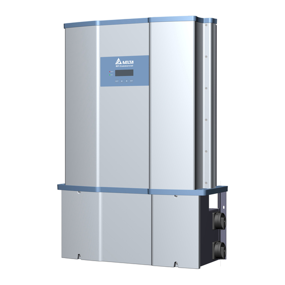
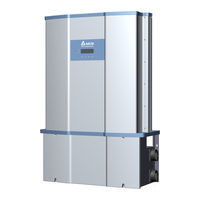
Delta M80U Operation And Installation Manual (112 pages)
Grid-tie Transformerless Solar Inverter
Brand:
Delta
| Category:
Inverter
| Size: 17.77 MB
Table of Contents
Table of Contents
3
1 Safety
10
Information of the Inverter
10
Legal Provisions
10
Target Group
10
General Safety
11
Condition of Use
11
Symbols
12
2 Introduction
14
Valid Model
14
Product Overview
15
Figure 2-2: Overview
16
Figure 2-3: Rating Labels of M42/36/28U
17
Table 2-2: Rating Label Explanation of M42/36/28U
18
Figure 2-4: External View and Wiring Box Layout for 120 Models
19
Figure 2-5: External View and Wiring Box Layout for 121 Models
20
Figure 2-6: External View and Wiring Box Layout for 122 Models
21
Figure 2-7: Wiring Box Layouts
22
3 Installation
23
Mechanical Installation
23
Vertical Wall Mount
23
Horizontal or Tilt Mount
24
Figure 3-1: Inverter Dimensions
25
Figure 3-2: Mounting Bracket Dimensions
26
Figure 3-4: Permitted Mounting Positions
27
Figure 3-6: Wall Mount Fixed Prior to Inverter
28
Figure 3-8: Required Mounting Clearances
29
Accessories
30
Wiring Box Cover
33
Electrical Installation for AC Wiring
33
AC Grid Types and Connections
34
Required Protective Devices for M42/36/28U AC Grid
34
AC Wiring Preparation (All Models)
34
AC Switch Terminals -Prewire Set-Up
35
AC Wiring for All Models
36
Electrical Installation for DC Wiring
37
DC Wiring Installation for 120 Models
38
DC Wiring Installation for 121 Models
39
Figure 3-15: Guideline for Aluminum Conductor
40
DC Wiring Installation for 122 Models
41
Ground Bar Locations for 120/121 Models
42
DC Side Ground Bar for 122 Models
43
Communication Module Connections
44
Accessing the Communication Module
45
Connection
46
Figure 3-22: Multiinverter Connection Illustration
47
EPO Function & Digital Input
48
Dry Contact Connection
49
On-Site Insulation Test
50
4 Commissioning
51
Display Operation Introduction
51
Figure 4-1: Front Panel Display
51
First Startup
53
Home Page
54
Main Menu
54
Power Meter
55
String Monitoring (120&122 Models)
55
Energy Log
56
Event Log
56
Inverter Information
57
General Settings
57
Install Settings
58
Inverter ID
59
Insulation
59
Grid Code
59
Figure 4-10: Inverter ID Screen Display
59
Grid Settings
60
Dry Contact Set-Up
61
Potential Induced Degradation
62
Residual Current Monitoring Unit (RCMU)
62
Emergency Power-Off Enable
62
AC Connection
63
Anti-Islanding
63
DC Arc Fault Circuit Interrupter (AFCI)
63
Figure 4-17: AC Connection
63
Grid Code Confirm
64
Active / Reactive Power
65
Power Limit
65
Power Vs. Frequency
65
P(V)
66
Constant Cosphi
67
Cosphi (P)
67
Figure 4-26: Constant Cosphi Screens
67
Constant Q
68
Q(V)
68
FRT (Fault Ride Through)
69
Q(V)
69
5 Maintenance
70
Removing and Replacing the Wiring Box (WB) Cover
70
Figure 5-1: Removing and Reinstalling the WB Cover
70
Removing the WB Cover
71
Replacing the WB Cover
71
Replacement of Surge Protection Devices (SPD)
72
Figure 5-4: Display Indicating AC and DC SPD Failure
73
Figure 5-5: Location of SPD Modules Inside Various WB Versions
74
Figure 5-6: Remove Screws as Indicated Unplug Connectors
75
Replace Internal String Fuse
76
Table 5-2: Combiner Fuse Specification
76
Figure 5-7: Fuse Holder Locations for 120/122 Models
77
Figure 5-9: String Monitor
78
Smart Fans Replacement and Filter Cleaning
79
Figure 5-10: Smart Fans Location on Power Module Chassis
79
Figure 5-11: Power Module Fan Tray
80
Power Module (PM) Fan Tray
81
PM Fan Tray Removal Procedure
81
Figure 5-12: Disassembling Fan Tray from PM Chassis (Showing One Side Only)
82
Procedures to Remove PM Air Inlet Filter
83
De-Commissioning
84
6 Error Message and Trouble Shooting
86
Error Codes
86
Table 6-1A: Error Codes and Messages
86
Warning Codes
87
Fault Codes
88
Table 6-3A: Fault Codes & Messages
88
Table 6-3C: Fault Codes & Messages
90
Table 6-3D: Fault Codes & Messages
91
Calling for Help
92
Service Call Checklist
92
7 Technical Data
93
Technical of M42U Series
93
Technical of M36U Series
94
Technical of M28U Series
95
Communications
96
Certifications
96
Smart Inverter Functionality
96
General Data
96
Figure 7-1: Thermal Derating Curve of M42U
97
Figure 7-2: Thermal Derating Curve of M36U
98
Figure 7-3: Thermal Derating Curve of M28U
99
Appendix A-1: Low and High Voltage Ride-Through Set-Points and Timing Per Table SA9.1
100
APPENDIX: Grid Support Utility Interactive Inverters
100
Appendix A: CA Rule 21
100
Appendix A-3: CA R21 Settings – Normal Ramp Rate (RR) & Soft-Start Ramp Rate (SS)
101
Appendix A-5: CA R21 Settings - Specified Power Factor
102
Appendix A-4: CA R21 Settings - Soft-Start Ramp Rate Test
102
Appendix A-2: Low and High Frequency Ride-Through Set-Points and Timing Per Table SA10.1 100
102
Appendix A-6: CA R21 Settings – Volt/Var Mode (Q(V))
102
Appendix A-7: CA R21 Settings - Frequency-Watt (FW)
103
Appendix A-8: CA R21 Settings – Volt-Watt (VW)
103
Appendix B-1: Full Frequency Ride-Through Settings for O'ahu, Hawai'I Island, and Maui (HECO A)
104
Figure B-3: Details of HECO a & B: L/H VRT Via LCD Settings Menu
106
Appendix B: HECO
104
Appendix B-2:Full Frequency Ride-Through Settings for Moloka'I and Lana'I (HECO B) 104
107
Appendix B-3:Full Voltage Ride-Through Settings for O'ahu, Hawai'I Island, Maui, Moloka'I, and Lana'i104
107
Appendix C-1: Assembly Note for All Model
107
Appendix C: Assembly Note
107
Appendix C-2:Assembly Note for 120 Model
109
Appendix C-3: Assembly Note for 121 Model
109
Appendix C-4: Assembly Note for 122 Model
110
Advertisement
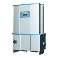
Delta M80U Operation And Installation Manual (130 pages)
Grid-tie Transformerless Solar Inverter
Brand:
Delta
| Category:
Inverter
| Size: 28.4 MB
Table of Contents
Table of Contents
3
1 Safety
10
Information of the Inverter
10
Legal Provisions
10
Target Group
10
General Safety
11
Condition of Use
11
Symbols
12
2 Introduction
14
Valid Model
14
Product Overview
15
3 Installation
24
Mechanical Installation
24
Vertical Wall Mount
24
Horizontal or Tilt Mount
25
Mounting Bracket
27
New Models with New Version of Mounting Bracket
28
Old Models with New Version of Mounting Bracket
30
Accessories
35
Wiring Box Cover
38
Electrical Installation for AC Wiring
38
AC Grid Types and Connections
39
Required Protective Devices for M80U / M60U
39
AC Wiring Preparation (All Models)
39
AC Switch Terminals -Prewire Set-Up
40
AC Wiring for M80/60U
42
120 Models
42
AC Wiring for M80/60U
44
121 Models (with RSD)
44
AC Wiring for M80/60U Models (Without RSD)
45
AC Wiring for M80/60U
45
AC Wiring for M80/60U Models
46
AC Wiring for M80/60U
46
Electrical Installation for DC Wiring
47
DC Wiring Installation for M80/60U _120 Models
48
DC Wiring Installation for M80/60U
50
121 Models
50
DC Wiring Installation for M80/60U
53
Ground Bar Locations
55
DC Side Ground Bar for 121/122 Models
56
Communication Module Connections
57
Accessing the Communication Module
58
Connection
59
EPO Function & Digital Input
61
Rapid Shutdown System Connection
62
On-Site Insulation Test
63
4 Commissioning
64
Display Operation Introduction
64
First Startup
66
Home Page
67
Main Menu
67
Power Meter
68
122 )
68
Energy Log
69
Event Log
69
Inverter Information
70
General Settings
70
Install Settings
71
Inverter ID
72
Insulation
72
Grid Code
72
Grid Settings
73
Potential Induced Degradation
74
Residual Current Monitoring Unit (RCMU)
74
Emergency Power-Off Enable
75
AC Connection
75
Anti-Islanding
75
DC Arc Fault Circuit Interrupter (AFCI)
76
Grid Code Confirm
76
Active / Reactive Power
77
Power Limit
77
Power Vs. Frequency
78
P(V)
79
Constant Cosphi
79
Cosphi (P)
80
Constant Q
81
Q(V)
81
FRT (Fault Ride Through)
82
5 Maintenance
83
Removing and Re-Installing the Wiring Box (WB) Cover
83
Removing the WB Cover
84
Re-Installing the WB Cover
84
Replacement of Surge Protection Devices (SPD)
85
Replace Internal String Fuse
90
Smart Fans Replacement and Filter Cleaning
94
Wiring Box (WB) Compartment Fan
97
Power Module (PM) Fan Tray
98
PM Fan Tray Removal Procedure
98
Procedures to Remove PM Air Inlet Filter
100
Release AFCI Fault Protection
100
Commissioning
101
6 Error Message and Trouble Shooting
103
Error Codes
103
Warning Codes
104
Fault Codes
105
Calling for Help
109
Service Call Checklist
109
7 Technical Information
110
Technical of M80U Series
110
Technical of M60U Series
113
Appendix A-1: Low and High Voltage Ride-Through Set-Points and Timing Per Table SA9.1D
116
Appendix A-2: Low and High Frequency Ride-Through Set-Points and Timing Per Table SA10.1
116
APPENDIX: Grid Support Utility Interactive Inverters
116
Appendix A: Rule 21
116
Appendix A-3: CA R21 Settings - Normal Ramp Rate (RR) & Soft-Start Ramp Rate (SS)
117
Appendix A-4: CA R21 Settings - Soft-Start Ramp Rate Test
117
Appendix A-5: CA R21 Settings - Specified Power Factor
117
Appendix A-6: CA R21 Settings - Volt/Var Mode (Q(V))
118
Appendix A-7: CA R21 Settings - Frequency-Watt (FW)
118
Appendix A-8: CA R21 Settings - Volt-Watt (VW)
119
Appendix B-1: Full Frequency Ride-Through Settings for O'ahu, Hawai'I Island, and Maui (HECO A)
120
Appendix B-2: Full Frequency Ride-Through Settings for Moloka'I and Lana'I (HECO B)
120
Appendix B-3: Full Voltage Ride-Through Settings for O'ahu, Hawai'I Island, Maui, Moloka'I, and Lana'I
120
Appendix B: HECO
120
Appendix C-1: Assembly Note for All Model
123
Appendix C: Assembly Note
123
Appendix C-2: Assembly Note for 120 Model
124
Appendix C-3: Assembly Note for 121 Model (with RSD)
125
Appendix C-4: Assembly Note for 121 Model (Without RSD)
126
Appendix C-5: Assembly Note for 122 Model
127
Advertisement
Related Products
Delta M88H_121 (ST)
Delta M88H_122 (CF)
Delta M8-TL-US
Delta M88H_121 ST
Delta M88H_122 CF
Delta M8A
Delta M88 Series
Delta M88H
Delta M88H 121
Delta M88H 122
Delta Categories
Plumbing Product
Kitchen & Bath Fixtures
Bathroom Fixtures
Saw
Power Supply
More Delta Manuals
Login
Sign In
OR
Sign in with Facebook
Sign in with Google
Upload manual
Upload from disk
Upload from URL