Sign In
Upload
Manuals
Brands
Danfoss Manuals
Water Filtration Systems
VLT AAF006
Danfoss VLT AAF006 Manuals
Manuals and User Guides for Danfoss VLT AAF006. We have
2
Danfoss VLT AAF006 manuals available for free PDF download: Service Manual, Operating Instructions Manual
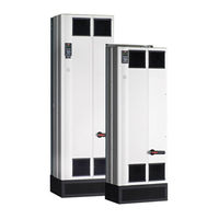
Danfoss VLT AAF006 Service Manual (98 pages)
Advanced Active Filter D and E Frame
Brand:
Danfoss
| Category:
Water Filtration Systems
| Size: 8.3 MB
Table of Contents
Table of Contents
2
Introduction
8
VLT Active Filter Product Overview
8
For Your Safety
8
Warnings
8
Electrostatic Discharge (ESD)
8
Frame Size Definitions
9
Rating Tables
10
Fuses
11
Current Transducers
11
General Torque Tightening Values
12
Tools Required
12
Exploded Views
13
Exploded Views E-Frame
13
Operator Interface and Active Filter Control
14
Introduction
14
User Interface
14
LCP Layout
14
Setting LCP Display Values
15
Display Menu Keys
15
Navigation Keys
16
Operation Keys
16
Tips and Tricks
17
Status Messages
17
Status Message Definitions
17
Service Functions
18
Filter Inputs and Outputs
18
Current Transformers
18
Filter CT Input
18
External CT Input
18
Control Wiring Input/Output
20
Serial Communication Wiring
20
Relay Options
21
Control Terminals
21
Control Terminal Functions
22
Grounding Shielded Control Cables
24
Internal Active Filter Operation
26
General
26
Control Card
26
Active Filter Card
27
Control to Power Interface
27
Filter Power Section
28
Additional Circuitry
28
AC Contactor
28
Soft Charge Circuit
28
Additional Thermal Protection
29
Current Transducers
29
Cooling Fans
29
Fan Speed Control
29
Low Harmonic Drive
30
Troubleshooting
32
Troubleshooting Tips
32
Fault Symptom Troubleshooting
32
Visual Inspection
33
Fault Symptoms
34
No Display
34
Intermittent Display
34
Warning/Alarm Messages
35
Warning/Alarm Code List
35
After Repair Tests
43
Active Filter and the Power Grid
44
Grid Variations
44
Grid Configurations
44
Grid Impedance
44
Voltage Pre-Distortions
44
Basic Troubleshooting Background
44
Line Phase Loss and Unbalanced Phase Trips
44
Voltage Dips and Flickers
44
Compatibility with Other Equipment on the same Line Power
45
Line Power Resonances
45
Control Logic Problems
45
Programming Problems
46
Internal Active Filter Problems
46
Overtemperature Faults
46
Current Feedback Problems
46
Noise on CT Input
47
Effect of EMI
47
Test Procedures
48
Introduction
48
Tools Required for Testing
49
Signal Test Board
49
Static Test Procedures
49
Inverter Section Tests
49
Inverter Test Part I
49
Inverter Test Part
49
Inverter Test Part
50
Gate Resistor Test
50
Intermediate Section Tests
50
Heatsink Temperature Sensor Test
51
Fan Continuity Tests
51
Fan Fuse Test
51
Ohm Test of Transformer
51
Ohm Test of Fans
51
AC Line Power Contactor and Soft Charge Contactor Tests
52
Dynamic Test Procedures
52
No Display Test
52
Input Voltage Test
52
Control Card Basic Voltage Test
53
Switch Mode Power Supply (SMPS) Test
53
Current Sensors Test CT1, CT2, CT3
54
Input Terminal Signal Tests
54
Line Power Resonance Test
55
Control Card Digital Inputs/Outputs Test
55
After Repair Tests
55
Frame Sizes Disassembly and Assembly Instructions
58
Electrostatic Discharge (ESD)
58
Passive Section (Top) Instructions
59
Control Card and Control Card Mounting Plate
60
MG90Z122 - VLT ® Is a Registered Danfoss Trademark
60
Control Assembly Support Bracket
60
Active Filter Card
60
Power Card
61
Power Card Mounting Plate
62
AC Capacitors
63
AC Capacitor Current Sensor (CT4, CT5, CT6)
64
AC Contactors
64
Movs
65
Discharge Card
65
Soft Charge Resistor
65
Active Side (Bottom) Instructions
66
Input Terminal Mounting Plate
66
Gate Drive Card
68
Contactor Transformer
68
Common Mode (CM) RFI Filter Card
68
Differential Mode (DM) RFI Filter Card
69
Capacitor Bank Assembly
69
IGBT Modules
70
IGBT Current Sensors CT1, CT2, and CT3
71
Damping Resistors
71
Fan Transformer
71
Fan
71
Frame Sizes Disassembly and Assembly Instructions
72
Electrostatic Discharge (ESD)
72
Passive Section (Top) Instructions
73
Control Card and Control Card Mounting Plate
74
Soft Charge Resistor
81
Active Section (Bottom) Instructions
81
Input Terminal Mounting Plate
81
Gate Drive Card Mounting Plate
83
Gate Drive Card
83
Upper Capacitor Bank Assembly
84
Lower Capacitor Bank Assembly
85
IGBT Modules
86
IGBT Current Sensors CT1, CT2, and CT3
88
Fan Transformer
89
Fan
89
Damping Resistors
89
Special Test Equipment
90
Test Equipment
90
Signal Test Board (P/N 176F8437)
90
Signal Test Board Pin Outs: Description and Voltage Levels
90
Advertisement
Danfoss
VLT AAF006
Operating Instructions Manual
Danfoss VLT AAF006 Operating Instructions Manual (94 pages)
Active Filter
Brand:
Danfoss
| Category:
Water Filtration Systems
| Size: 5.24 MB
Table of Contents
Table of Contents
4
1 Introduction
7
Purpose of the Manual
7
Additional Resources
7
Product Overview
7
Working Principle
7
IEEE519 Compliance
8
Ordering Information
9
Filter Configurator
9
Ordering Form Type Code
9
2 Safety
10
Safety Symbols
10
Qualified Personnel
10
Safety Precautions
10
3 Mechanical Installation
11
Pre-Installation
11
Planning the Installation Site
11
Receiving the Active Filter
11
Transportation and Unpacking
11
Lifting
11
Mechanical Dimensions
12
Mechanical Installation
14
Tools Needed
14
Clearance Requirements
14
Power Terminal Locations
15
Cooling and Airflow
16
Gland/Conduit Entry - IP21 (NEMA 1) and IP54 (NEMA12)
17
4 Electrical Installation
18
Safety Instructions
18
Power Connections
18
Grounding
19
EMC Interference
20
Extra Protection (RCD)
21
RFI Switch
21
Torque
21
Current Transformer (CT)
21
Auto CT Detection
25
Danfoss A/S © 09/2014 All Rights Reserved
25
Summation Transformers
26
Operating with Capacitor Banks
27
Fuses
29
Mains Disconnectors
29
Control and CT Cable Routing
29
Control Wire Installation
29
Unscreened Control Wires
30
Electrical Installation, Control Cables
31
Installation Checklist
32
5 User Interface
33
Local Control Panel Operation
33
Modes of Operation
33
How to Operate Graphical LCP (GLCP)
33
Changing Data
36
Changing a Text Value
36
Changing a Group of Numeric Data Values
36
Changing of Data Value, Step-By-Step
36
Readout and Programming of Indexed Parameters
36
Quick Transfer of Parameter Settings with the LCP
37
Initialisation to Default Settings
37
RS485 Bus Connection
38
Connection to a PC
38
6 Applications and Basic Programming
39
Paralleling of Active Filters
39
Programming
41
Description of Parameters
44
Operation/Display
44
Digital I/O Mode
49
General Settings
51
Trip Reset
53
Drive Information
55
Data Readouts
59
300-** AF Settings
61
301-** AF Readouts
64
Parameter Lists
65
Default Settings
65
Operation/Display
66
Digital In/Out
67
Comm. and Options
67
Special Functions
68
FC Information
68
Data Readouts
70
300-** AF Settings
71
301-** AF Readouts
71
7 RS485 Installation and Set-Up
72
Installation and Set-Up
72
Network Configuration
73
FC Protocol Message Framing Structure
73
Conversion
76
How to Access Parameters in Modbus RTU
77
8 Maintenance, Diagnostics and Troubleshooting
78
Maintenance and Service
78
Warning and Alarm Types
78
Active Filter Warning and Alarm Definitions
79
9 Specifications
84
Power Rating
84
Derating for Altitude and Ambient Temperature
87
Acoustic Noise
87
10 Appendix
88
Abbreviations and Conventions
88
Index
89
Advertisement
Related Products
Danfoss VLT AHF005
Danfoss VLT AHF010
Danfoss VLT AutomationDrive FC 300
Danfoss VLT AutomationDrive
Danfoss VLT AQUA Drive Series
Danfoss VLT AutomationDrive FC300
Danfoss VLT A1-A5
Danfoss VLT AQUA Drive D-Frame
Danfoss 084H5003
Danfoss Categories
Controller
DC Drives
Thermostat
Control Unit
Water Pump
More Danfoss Manuals
Login
Sign In
OR
Sign in with Facebook
Sign in with Google
Upload manual
Upload from disk
Upload from URL