Sign In
Upload
Manuals
Brands
Codan Manuals
Transceiver
NGT 2030
Codan NGT 2030 HF Transceiver Manuals
Manuals and User Guides for Codan NGT 2030 HF Transceiver. We have
1
Codan NGT 2030 HF Transceiver manual available for free PDF download: Technical & Service Manual
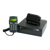
Codan NGT 2030 Technical & Service Manual (840 pages)
Transceiver System
Brand:
Codan
| Category:
Transceiver
| Size: 44.3 MB
Table of Contents
Table of Contents
3
List of Figures
13
About this Manual
25
Standards and Icons
28
Definitions
29
Acronyms and Abbreviations
29
Glossary
35
Circuit Reference Designations
37
Units
38
Unit Multipliers
39
About this Issue
40
The 2011
40
Compliance
41
Introduction
42
European Radio and Telecommunications Terminal Equipment Directive
43
Electromagnetic Compatibility and Safety Notices
45
FCC Compliance
47
IC Certification
48
C-Tick Approval
48
Maintenance
49
General
49
CMOS Devices
50
Circuit Boards
50
Transmitter Precautions
52
Probe Precautions
52
Contact Information
53
Ordering Information
55
Component Substitution
56
NGT-Index
57
NGT-Overview and Specifications
64
Overview
64
Figure 1: Relationship of the 2010 RF Unit, 2030 Junction Box, and 2020 Handset
64
Figure 2: Relationship of the 2011/2012 RF Unit and 2020 Handset
65
Specifications
66
General
66
Receiver
68
Transmitter
69
Pin Connections
71
RF Unit
71
Figure 3: Rear Panel of the 2010 RF Unit
71
Figure 4: Rear Panel of the 2011 RF Unit
71
Figure 5: Rear Panel of the 2012 RF Unit
71
Figure 6: Front View of the CIB Connector on the RF Unit (2010 Only)
72
Figure 7: Front View of the Antenna Control Connector on the RF Unit
73
Figure 8: Front View of the Fan Connector on the RF Unit
74
Figure 9: Front View of the 10-Way Connector on the RF Unit (2011/2012 Only)
75
Figure 10: Front View of the 4-Way Connector on the RF Unit (2011/2012 Only)
76
Figure 11: Front View of the 6-Way Connector on the RF Unit (2011/2012 Only)
76
Figure 12: Front View of the Handset and Speaker Connector Attached to the RF Unit
77
(2011/2012 Only)
77
Figure 13: Front View of the 15-Way GPIO Connector on the RF Unit (2012 Only)
78
Junction Box (Used with 2010 RF Units Only)
79
Figure 14: Connector Panel of the Junction Box
79
Figure 15: Front View of the Handset Connector on the Junction Box
79
Figure 16: Front View of a CIB Connector on the Junction Box
80
Figure 17: Front View of the 9-Way Serial Data Connector on the Junction Box
81
Figure 18: Front View of the 15-Way GPIO Connector on the Junction Box
82
Desk Console
83
NGT-Brief Description
86
General Information
89
Transmit Path
91
Handset Transmit Path
91
Junction Box Transmit Path
91
RF Unit Transmit Path
91
Receive Path
92
RF Unit Receive Path
92
Junction Box Receive Path
92
Synthesiser Operation
93
Control and Switching
93
NGT-Brief Description (2011/2012)
96
General Information
99
Transmit Path
100
Handset Transmit Path
100
RF Unit Transmit Path
100
Receive Path
101
RF Unit Receive Path
101
Synthesiser Operation
102
Control and Switching
102
NGT-Technical Description
104
Power on
104
Power off
105
Supply Voltages
106
Handset
106
Junction Box
106
RF Unit
107
Transmit Path
109
Handset Microphone Amplifier Transmit Path
109
Junction Box Transmit Path
109
Figure 19: Representation of the Waveform as Measured at TP2
110
Codan Interconnect Bus Transmit Path
111
RF Unit-Audio Interface PCB Transmit Path
111
RF Unit-Application Processor PCB Transmit Path
112
Figure 20: Representation of Compression Function by IC5
112
RF Unit-RF/IF PCB Transmit Path
113
RF Unit-PA PCB Transmit Path
115
Receive Path
121
Input Low-Pass Filters
121
Broadcast Filter and RF Amplifier
121
First Mixer
121
45 Mhz Band-Pass Filter and Amplifier
121
Second Mixer
122
Noise Limiter
122
455 Khz Filter and if Amplifier
123
Automatic Gain Control
124
Demodulator
125
RF Unit-Audio Interface PCB Receive Path
125
Codan Interconnect Bus Receive Path
126
Junction Box Receive Path
126
Frequency Control
127
Reference Oscillator
127
Oven Controller
127
Direct Digital Synthesis
128
VCO and Phase Lock Loop
129
26 V Power Supply
129
Microprocessors and Control
130
Handset Microprocessor and Control
130
Junction Box Microprocessor and Control
131
RF Unit Microprocessors and Control
132
Desk Console
134
Internal Voice Encryptor
135
Second if Filter Option
136
NGT-Technical Description (2011/2012)
136
Power on
138
Power off
139
Supply Voltages
140
Handset
140
RF Unit
140
Transmit Path
143
Handset Microphone Amplifier Transmit Path
143
RF Unit-Audio & Interconnect PCB (2011)/Audio Interconnect & Data I/O PCB
143
RF Unit-Application Processor Handset I/F 3 V PCB (2011)/Application Processor Handset & Data I/F PCB (2012) Transmit Path
144
RF Unit-RF/IF PCB Transmit Path
144
Figure 21: Representation of Compression Function by IC7
144
RF Unit-PA PCB Transmit Path
147
Receive Path
150
Input Low-Pass Filters
150
Broadcast Filter and RF Amplifier
150
First Mixer
150
45 Mhz Band-Pass Filter and Amplifier
150
Second Mixer
151
Noise Limiter
151
455 Khz Filter and if Amplifier
151
Automatic Gain Control
152
Demodulator
153
RF Unit-Audio & Interconnect PCB (2011)/Audio Interconnect & Data I/O PCB
153
Frequency Control
155
Reference Oscillator
155
Oven Controller
155
Direct Digital Synthesis
155
VCO and Phase Lock Loop
156
26 V Power Supply
157
Microprocessors and Control
158
Handset Microprocessor and Control
158
RF Unit-Microprocessors and Control
159
Internal Voice Encryptor
162
NGT-Channel Additions
163
General
164
Options
164
Figure 22: Position of TPE Link on the Microprocessor PCB in the Junction Box
165
Figure 23: Position of TPE Link on the Application Processor Handset I/F 3 V PCB
165
Figure 24: Position of TPE Link on the Application Processor Handset & Data I/F PCB
166
Programming Channels
168
Creating a Channel
168
Creating a Channel with the Txd Option
171
Renaming a Channel
173
Copying a Channel
175
Editing a Channel
176
Deleting a Channel
178
NGT-Checks and Adjustments
180
Test Equipment Required
180
Voltage Regulators
181
Handset Voltages
181
Junction Box Voltages
181
RF Unit Voltages
182
Crystal Oven
186
Low-Pass Filters
186
Service Mode
187
General
187
Accessing Service Mode
188
Figure 25: Position of Link 11 on the Microprocessor PCB in the Junction Box
188
In the 2011
189
Figure 26: Position of Link a on the Application Processor Handset I/F 3 V PCB in
189
Figure 27: Position of Link a on the Application Processor Handset & Data I/F PCB
189
Returning to Normal Mode
192
Testing the Keypad and Display
193
Adjustment Locations and Test Points
194
Figure 28: RF/IF PCB in the RF Unit (08-05261)
194
Figure 29: RF/IF PCB in the RF Unit (08-05889)
195
Figure 30: PA PCB in the RF Unit (08-05415 or 08-05511)
195
Figure 31: PA PCB in the RF Unit (08-05869)
196
Figure 32: PA PCB in the RF Unit (08-06461)
196
Figure 33: Filter and Control PCB in the RF Unit (08-05416)
197
Figure 34: Filter and Control PCB in the RF Unit (08-05910)
197
Figure 35: Audio Interface PCB in the RF Unit (08-05266, 2010 Only)
198
Checking the Voltage-Controlled Oscillator
200
Aligning the 45 Mhz Filters
201
Aligning the Rx Filter
201
Aligning the Tx Filter
202
Aligning the 455 Khz if and Noise Limiter
203
Adjusting the Exciter Output Level
204
Adjusting Carrier Re-Insertion
205
Adjusting the Exciter Output Spurious Balance
206
Adjusting Frequency
207
Adjusting Mute
209
Adjusting the PA
210
Adjusting the Driver Bias
210
Adjusting High Output Power
214
Adjusting Low Output Power
216
Adjusting the Bias Gain
216
Adjusting the Active Bias
218
Adjusting Balance Control
219
Checking Intermodulation
221
Adjusting the PA Gain
223
Checking Performance of the Receiver
224
Checking the Sensitivity and (Signal+Noise)/Noise Ratio
224
Checking the AGC
225
Checking the Audio Output
225
Checking the Selectivity
226
Checking the Noise Limiter
227
Checking Performance of the Transmitter
228
Checking the Transmit Frequency
228
Checking the ALC
228
Checking Power Output and Intermodulation
229
Advertisement
Advertisement
Related Products
Codan NGT AR
Codan NGT SR
Codan NGT VR
Codan NGT 2010 RF
Codan NGT 2011 RF
Codan NGT 2012 RF
Codan NGT 2020
Codan 2110 series
Codan 2110v
Codan 5700 series
Codan Categories
Transceiver
Radio
Receiver
Antenna
Modem
More Codan Manuals
Login
Sign In
OR
Sign in with Facebook
Sign in with Google
Upload manual
Upload from disk
Upload from URL