Sign In
Upload
Manuals
Brands
Bender Manuals
Measuring Instruments
ISOMETER isoRW685W
Bender ISOMETER isoRW685W Manuals
Manuals and User Guides for Bender ISOMETER isoRW685W. We have
1
Bender ISOMETER isoRW685W manual available for free PDF download: Manual
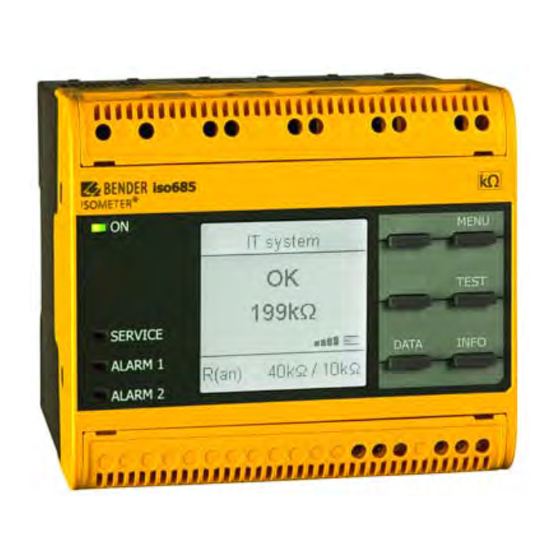
Bender ISOMETER isoRW685W Manual (62 pages)
Insulation Monitoring Device for IT AC systems with galvanically connected rectifiers and inverters and for IT DC systems specific to railway applications
Brand:
Bender
| Category:
Measuring Instruments
| Size: 2 MB
Table of Contents
ON (Operation LED)
2
Table of Contents
3
Important Information
6
How to Use this Manual
6
Technical Support
6
End Customer Support and Advice
6
Repair
6
Customer Service
6
Training Courses
7
Delivery Conditions
7
Storage
7
Warranty and Liability
7
Disposal
7
Safety Instructions
8
General Safety Instructions
8
Work Activities on Electrical Installations
8
Device-Specific Safety Information
8
Intended Use
8
Function
9
Features
9
Product Description
9
Function Description
9
Interfaces
10
Self Test
10
Device Overview
11
Dimensions
11
Device Variants
11
Connection and Panel
12
Display Elements and Device Buttons
13
Display Elements
13
Device Buttons
13
Service
13
Operating and Navigating
14
Menu Selection
14
List Selection
14
Parameter Selection and Value Adjustment
14
Character Input
14
Mounting
15
Common Information
15
Mounting Spaces
15
Screw Mounting
16
DIN Rail Mounting
16
Connection
17
Connection Requirements
17
Connection to a 3(N)AC System
18
Connection to an AC System
18
Connection to a DC System
19
Connection to the Supply Voltage
19
Connection to the X1 Interface
20
Connection to the Ethernet Interface ETH
20
Connection to Relay Interfaces 1 und 2
20
Position the Terminal Covers and Click Them into Place
21
Commissioning
22
General Initial Commissioning Process
22
Initial Commissioning
22
Setting Language
22
Setting Date and Time
22
Setting System Type
23
Select a Coupling Device
23
Setting Profile
23
Setting Response Value Ran1 for Alarm 1
23
Setting Response Value Ran2 for Alarm 2
23
Alarm 1
23
Alarm 2
23
Recommissioning
24
Configuring Password Protection for the ISOMETER® Iso685
24
Display
25
Standard Display
25
Fault Display (Active)
25
Fault Display (Inactive)
26
Acknowledging a Fault Message
26
History Memory
26
Data-Isograph
27
Initial Measuring
27
Automatic Test
27
Settings
28
Menustructure
28
Settings in the Device Menu
29
(1.0) Alarm Settings
29
(1.1) Insulation Alarm
29
(1.1.1) Alarm 1
29
(1.1.2) Alarm 2
29
(1.1.3) Fault Memory
29
(1.2) DC Alarm
29
(1.2.1) Alarm
29
(1.2.2) U(DC-E)
29
(1.3) Profile
30
(1.4) System Type
30
Coupling
30
T(Start)
30
(1.7) Coupling Monitoring
30
(1.8) Inputs
30
(1.8.1) Digital 1
30
2) Digital 2
31
(1.8.3) Digital 3
31
(1.9) Outputs
31
(1.9.1) Relay 1
31
(1.9.2) Relais 2
32
(1.9.3) Digital 1
32
(1.9.4) Digital 2
33
(1.9.5) Buzzer
33
6) Analogue
33
(2.0) Data Measured Values
34
(3.0) Steuerung
34
(3.1) Test
34
Reset
34
(3.3) Start Initial Measurement
34
Device
34
History
35
Device Settings
35
Language
35
Clock
35
1) Time
35
2) Format (Time)
35
3) Summer Time
35
4) Date
35
(5.2.5) Format (Date)
35
(5.2.6) Ntp
35
(5.3.3) Bcom
36
(5.3.4) Modbus/Tcp
36
(5.3.5) Rs-485
36
(5.3.6) Modbus RTU
37
(5.4) Display
37
(5.4.1) Brightness
37
(5.4.2) Automatic Dimming
37
(5.5) Password
37
(5.5.1) Password
37
(5.5.2) Status
37
(5.6) Commissioning
37
(5.7) Data Backup
37
(5.8) Activation
37
(6.0) Info
38
Device Communication
39
Ethernet Interface
39
Bcom
39
Modbus/Tcp
39
Web Server
39
Conventions
39
Functions
39
User Interface
40
Menu Structure
40
Device Address
40
Parameter Changes
41
Changing Parameters in the Web Browser
42
Changing Parameters in the Device Menu When the Web Browser Is Open
42
Write Access for Parameter Changes
42
BS Bus
43
Master-Slave Principle
43
Addresses and Address Ranges on the BS Bus
43
Specifications/Cables
43
Cable Routing
43
Modbus RTU
43
Isodata Protocol
44
Isodata-Protocol Table
45
Number
47
Coupling Devices
48
Connection Using the AGH150W-4(DC)
48
Connection Using the AGH150W-4(3(N)AC)
48
Connection Using the AGH520S (3AC)
49
Connection Using the AGH520S (3(N)AC)
49
Connection Using the AGH204S-4
50
Connection Using the AGH676S-4
50
Alarm Messages
51
Measuring Value Alarms
51
General Alarms
51
Technical Data
53
Device Profiles
53
Diagrams
54
Response Time Profile Power Circuits
54
Response Time Control Circuits Profile
54
Response Time Generator Profile
54
Response Time High Capacitance Profile
54
Response Time Inverter > 10 Hz Profile
55
Response Time DC Alarm
55
Relative Uncertainty
55
Factory Settings Iso685-X
56
Tabular Data Isorw685W-D
57
Number
58
Standards and Certifications
59
Ordering Details Isorw685W-D
60
Device
60
Accessories
60
Suitable System Components
60
Glossary
61
Advertisement
Advertisement
Related Products
Bender ISOMETER isoRW425
Bender ISOMETER isoRW685W-D
Bender ISOMETER isoRW685W-D-B
Bender ISOMETER isoRW425-D4W-4
Bender ISOMETER IRDH275 Series
Bender ISOMETER IRDH275B Series
Bender ISOMETER iso685W-S-P
Bender ISOMETER isoHR685W-D-I-B
Bender ISOMETER isoLR1685DP-325
Bender ISOMETER isoBAT425
Bender Categories
Measuring Instruments
Monitor
Control Unit
Control Panel
Relays
More Bender Manuals
Login
Sign In
OR
Sign in with Facebook
Sign in with Google
Upload manual
Upload from disk
Upload from URL