Sign In
Upload
Manuals
Brands
Bender Manuals
Measuring Instruments
ISOMETER iso685-S-B
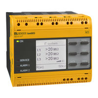
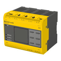
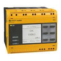
Bender ISOMETER iso685-S-B Manuals
Manuals and User Guides for Bender ISOMETER iso685-S-B. We have
6
Bender ISOMETER iso685-S-B manuals available for free PDF download: Manual, Quick Start Manual, Commissioning
Bender ISOMETER iso685-S-B Manual (69 pages)
Brand:
Bender
| Category:
Measuring Instruments
| Size: 3 MB
Table of Contents
Table of Contents
3
1 Important Information
6
How to Use this Manual
6
Technical Support
6
End Customer Support and Advice
6
Repair
6
Customer Service
6
Training Courses
7
Delivery Conditions
7
Storage
7
Warranty and Liability
7
Disposal
7
2 Safety Instructions
8
General Safety Instructions
8
Work Activities on Electrical Installations
8
Device-Specific Safety Information
8
Intended Use
8
3 Function
9
Features
9
Product Description
9
General Product Description
9
Special ISOMETER® Characteristics
9
Function Description
9
Interfaces
10
Self Test
10
4 Device Overview
11
Dimensions
11
Device Variants
11
Connection and Panel
12
Display Elements and Device Buttons
13
Display Elements
13
Device Buttons
13
Operating and Navigating
14
Menu Selection
14
List Selection
14
Parameter Selection and Value Adjustment
14
Character Input
14
5 Mounting
15
Common Information
15
Mounting Spaces
15
Screw Mounting
16
DIN Rail Mounting
16
6 Connection
17
Connection Requirements
17
Connection to a 3(N)AC System
18
Connection to an AC System
18
Connection to a DC System
19
Connection to the Supply Voltage
19
Connection to the X1 Interface
20
Connection to the Ethernet Interface ETH
20
Connection to Relay Interfaces 1 und 2
20
Position the Terminal Covers and Click Them into Place
21
7 Commissioning
22
General Initial Commissioning Process
22
Initial Commissioning
22
Setting Language
22
Setting Date and Time
22
Setting System Type
23
Select a Coupling Device
23
Setting Profile
23
Setting Response Value Ran1 for Alarm 1
23
Setting Response Value Ran2 for Alarm 2
23
Recommissioning
24
Configuring Password Protection for the ISOMETER® Iso685
24
8 Display
25
Standard Display
25
Fault Display (Active)
25
Fault Display (Inactive)
26
Acknowledging a Fault Message
26
History Memory
26
Data-Isograph
27
Initial Measuring
27
Isonet Operation
27
Isoloop Operation
27
Automatic Test
28
9 Settings
29
Menustructure
29
Settings in the Device Menu
30
Alarm Settings
30
(1.1.3) Fault Memory
30
(1.2) DC Alarm
30
(1.2.1) Alarm
30
(1.2.2) U(DC-E)
30
1) Alarm 1
30
2) Alarm 2
30
Insulation Alarm
30
(1.3) Profile
31
(1.4) System Type
31
(1.5) Coupling
31
(1.6) Isonet
31
(1.6.1) Isonet
31
(1.6.2) Number of Devices
31
(1.7) Isoloop
31
(1.7.1) Isoloop
31
(1.7.2) Measured Value Subscription
31
(1.8) (Start)
31
(1.10.1) Digital 1
32
(1.10.2) Digital 2
32
(1.10.3) Digital 3
32
1) Digital 1
32
(1.11) Outputs
33
(1.11.1) Relay 1
33
(1.11.2) Relais 2
34
(1.11.3) Digital 1
34
(1.11.4) Digital 2
34
(1.11.5) Buzzer
34
(1.11.6) Analogue
34
(2.0) Data Measured Values
36
Control
36
(3.1) Test
36
(3.2) Reset
36
(3.3) Start Initial Measurement
36
(3.4) Device
36
(3.5) Isonet Priority
36
(4.0) History
36
(5.0) Device Settings
36
(5.1) Language
36
(5.2.3) Summer Time
37
(5.2.4) Date
37
(5.2.5) Format (Date)
37
(5.2.6) Ntp
37
(5.2.7) NTP Server
37
(5.2.8) Utc
37
(5.3) Interface
37
(5.3.1) Write Access
37
(5.3.2) Ethernet
37
(5.3.3) Bcom
38
(5.3.4) Modbus/Tcp
38
(5.3.5) Rs-485
38
(5.3.6) Modbus RTU
38
(5.4) Display
38
(5.4.1) Brightness
38
(5.10) Software
39
(5.10.1) Update Via Interface
39
(5.4.2) Automatic Dimming
39
(5.5) Password
39
(5.5.1) Password
39
(5.5.2) Status
39
(5.6) Commissioning
39
(5.7) Data Backup
39
(5.8) Activation
39
(5.9) Factory Settings
39
10 Device Communication
40
Ethernet Interface
40
Bcom
40
Modbus/Tcp
40
Web Server
40
Conventions
40
Functions
40
User Interface
41
Menu Structure
41
Parameter Changes
42
Changing Parameters in the Web Browser
43
Changing Parameters in the Device Menu When the Web Browser Is Open
43
Write Access for Parameter Changes
43
BS Bus
44
Master-Slave Principle
44
Addresses and Address Ranges on the BS Bus
44
Specifications/Cables
44
Cable Routing
44
Modbus RTU
44
Isodata Protocol
45
Isodata-Protocol Table
46
11 Special Functions for Coupled IT Systems
49
Particularities When Monitoring Coupled IT Systems
49
System Isolation Via Digital Input with Two Coupled Systems
49
System Isolation Via Isonet
49
Systempictures
50
Configuration and Function
50
Isonet Priority
50
Isoloop
51
Preparing the Devices in an Interconnection
51
Creating Groups with the BCOM Group Manager
52
Configuration and Function on the ISOMETER
53
12 Coupling Devices
54
Connection Using the AGH150W-4(DC)
54
Connection Using the AGH150W-4(3(N)AC)
54
Connection Using the AGH520S (3AC)
55
Connection Using the AGH520S (3(N)AC)
55
Connection Using the AGH204S-4
56
Connection Using the AGH676S-4
56
13 Alarm Messages
57
Measured Value Alarms
57
General
57
Isonet
58
Isoloop
59
14 Technical Data
60
Device Profiles
60
Diagrams
61
Response Time Profile Power Circuits
61
Response Time Control Circuits Profile
61
Response Time Generator Profile
61
Response Time High Capacitance Profile
61
Response Time Inverter > 10 Hz Profile
62
Response Time DC Alarm
62
Relative Uncertainty
62
Factory Settings Iso685-X-B
63
Tabular Data Iso685-X-B
64
Standards and Certifications
67
Ordering Details
67
Device
67
Accessories
67
Suitable System Components
67
15 Glossary
68
Advertisement
Bender ISOMETER iso685-S-B Manual (68 pages)
Insulation Monitoring Device for IT AC systems with galvanically connected rectifiers and inverters and for IT DC systems
Brand:
Bender
| Category:
Measuring Instruments
| Size: 3 MB
Table of Contents
Table of Contents
3
1 Important Information
6
How to Use this Manual
6
Technical Support
6
First Level Support
6
Repair Service
6
Field Service
7
Training Courses
7
Delivery Conditions
7
Storage
7
Disposal
7
2 Safety Instructions
8
General Safety Instructions
8
Work Activities on Electrical Installations
8
Device-Specific Safety Information
8
Intended Use
9
3 Function
10
Features
10
Product Description
10
General Product Description
10
Special Characteristics of ISOMETER® Iso685-S-B with Front Panel
10
Functional Description
10
Interfaces
11
Self Test
11
4 Device Overview
12
Dimensions
12
Device Variants
13
Connections and Panel
14
Display Elements and Device Buttons
15
5 Mounting
16
General Instructions
16
Screw Mounting
16
DIN Rail Mounting
17
6 Connection
17
Connection Requirements
17
Connection to a 3(N)AC System
19
Connection to an AC System
19
Connection to a DC System
20
Connection to the X1 Interface
20
Connection to the Supply Voltage
21
Connection to the Ethernet Interface
21
Connection to the Relay 1 Interface (11 12 14)
22
Connection to the Relay 2 Interface (21 22 24)
22
7 Commissioning
23
General Initial Commissioning Process
23
Initial Commissioning
24
Set Language
24
Set Time and Date
24
Set System Type
24
Set Profile
24
Set Response Value Ran1 for Alarm 1
25
Set Response Value Ran2 for Alarm 2
25
Recommissioning
25
8 Display
26
Standard Display
26
Fault Display (Active)
26
Fault Display (Inactive)
27
Acknowledge Fault Memory
28
Data-Isograph
28
History Memory
29
Initial Measurement
29
Isonet Mode
30
9 Menu
31
Menu Structure
31
Operating and Navigating
32
Easy Operation
32
10 Settings
33
Settings in the Device Menu
33
Alarm Settings
33
(1.2) DC Alarm
33
(1.2.2) U(DC-E)
33
1) Alarm
33
Fault Memory
33
Insulation Alarm
33
(1.4) System Type
34
(1.5) Isonet
34
(1.5.1) Isonet
34
(1.5.2) Number of Devices
34
(1.6) Device
34
(1.7) T(Start)
34
(1.8) Coupling Monitoring
34
Profile
34
(1.9) Inputs
35
(1.9.1) Digital 1
35
(1.9.1.1) Mode
35
(1.9.1.2) T(On)
35
(1.9.1.3) T(Off)
35
(1.10) Outputs
36
(1.10.1) Relay 1
36
(1.10.1.1) Test
36
(1.10.1.2) Relay Mode
36
(1.9.1.4) Function
36
(1.9.2) Digital 2
36
(1.9.3) Digital 3
36
(1.10.1.4) Function 2
37
(1.10.1.5) Function 3
37
3) Function 1
37
(1.10.2) Relay 2
37
(1.10.3) Digital 1
37
(1.10.3.1) Test
38
(1.10.3.5) Function 3
38
2) Mode
38
3) Function 1
38
4) Function 2
38
(1.10.4) Digital 2
38
(1.10.5) Buzzer
38
(1.10.5.1) Test
38
(1.10.6) Analogue
38
(1.10.6.3) Test
39
1) Mode
39
2) Midscale
39
(1.10.6.4) Function
40
(2.0) Data Measured Values
40
(3.0) Control
40
(4.0) History
40
(5.0) Device Settings
40
(5.1) Language
40
(5.2) Clock
40
(5.2.1) Time
41
(5.2.2) Format (Time)
41
(5.2.3) Summer Time
41
(5.2.4) Date
41
(5.2.5) Format (Date)
41
(5.2.6) Ntp
41
(5.2.7) NTP Server
41
(5.2.8) Utc
41
(5.3) Interface
41
(5.3.1) Write Access
42
(5.3.2) Ethernet
42
1) Dhcp
42
1) System Name
42
2) Subsystem
42
3) Bcom
42
3) Device Address
42
4) Std. GW
42
5) DNS Server
42
6) Domain
42
1) Address
43
1) Brightness
43
1) Port 502
43
2) Status
43
5) BS Bus
43
Commissioning
43
Data Backup
43
Display
43
Password
43
Service
43
11 Device Communication
44
Ethernet Interface
44
Bcom
44
Modbus TCP
44
Web Server
44
BS Bus
48
12 Special Functions for Coupled IT Systems
49
Particularities When Monitoring Coupled IT Systems
49
System Isolation Via Digital Input with Two Coupled Systems
49
System Isolation Via Isonet
50
13 Device Profiles
52
14 Diagrams
53
Response Time Profile Power Circuits
53
Response Time Profile Control Circuits
53
Response Time Profile Generator
54
Response Time Profile High Capacitance
54
Response Time Profile Inverter > 10 Hz
55
Response Time DC Alarm
56
Relative Uncertainty
56
15 Alarm Messages
57
16 Factory Settings
59
17 Technical Data
60
Tabular Data
60
Option "W
63
Standards and Certifications
63
Ordering Details
63
18 Glossary
64
Index
65
Bender ISOMETER iso685-S-B Manual (59 pages)
Insulation Monitoring Device for IT AC systems with galvanically connected rectifiers and inverters and for IT DC systems
Brand:
Bender
| Category:
Measuring Instruments
| Size: 3 MB
Table of Contents
Table of Contents
3
Safety Instructions
7
Explanation of Symbols and Notes
7
Intended Use
7
Warranty and Liability
8
Personnel
8
About the Operating Manual
8
Hazards When Handling the ISOMETER® Iso685-D-B/-S-B
8
Inspection, Transport and Storage
8
Note
8
Function
9
Features
9
Product Description
9
Special Characteristics ISOMETER® Iso685-S-B with
9
Front Panel
9
Functional Description
9
Interfaces
10
Self-Test
10
Device Overview
11
Dimensions
11
Device Variants
12
Connections and Panel
13
Mounting
14
Screw Mounting
14
DIN Rail Mounting
14
Connection
15
Connection Conditions
15
Connection to a 3(N)AC System/System Type 3AC
16
Connection to an AC System/System Type AC
16
Connection to a DC System/System Type DC
17
Connection to the X1 Interface
17
Connection to the Supply Voltage
18
Connection to A1/+, A2
18
Connection to X1
18
Connection to the Ethernet Interface
19
Connection to the Relay 1 Interface (11 12 14)
19
Connection to the Relay-2 Interface (21 22 24)
20
Commissioning
20
Device Buttons
20
General Initial Commissioning Process
20
Initial Commissioning
21
Set Language
21
Set Time and Date
21
Set System Type
21
Set Profile
22
Set Response Value Ran1 for Alarm 1
22
Set Response Value Ran2 for Alarm 2
22
Recommissioning
22
Display
23
Standarddisplay
23
Fault Display (Active)
23
Fault Display (Inactive)
24
Acknowledge Fault Message
25
Data-Isograph
25
History Memory
26
Menu
27
Alarm Settings
28
Insulation Alarm
28
Alarm 1
28
Alarm 2
28
Fault Memory
28
Profile
28
System Type
28
Isonet
28
Number of Devices
28
Device
29
T(Start)
29
Coupling Monitoring
29
Inputs
29
Digital 1
29
Digital 2
29
Function
29
Mode
29
T(Off)
29
T(On)
29
Outputs
30
Function 1
30
Function 2
30
Function 3
30
Relay 1
30
Relay Mode
30
Test
30
Relay 2
30
Digital 1
31
Function 1
31
Function 2
31
Mode
31
Test
31
Digital 2
31
Buzzer
31
Function 3
31
Analog
31
Function
32
Scale Centre
32
Test
32
Data Measured Values
32
Control
32
History
32
Device Settings
33
Language
33
Clock
33
Date
33
Format (Date)
33
Format (Time)
33
Ntp
33
NTP Server
33
Summer Time
33
Time
33
Bcom
34
Dhcp
34
DNS Server
34
Domain
34
Ethernet
34
Interface
34
Std. GW
34
System Name
34
Utc
34
Write Access
34
Bms
35
Brightness
35
Commissioning
35
Data Backup
35
Display
35
Modbus/Tcp
35
Password
35
Port 502
35
Status
35
TTL for Subscription
35
Device Communication
36
Ethernet Interface
36
Bcom
36
Modbus/Tcp
36
Web Server
37
Special Functions for Coupled IT Systems
38
Particularities When Monitoring Coupled IT Systems
38
System Isolation Via Digital Input with Two Coupled Systems
38
System Isolation Via Digital Input with Several Coupled Systems
39
System Isolation Via Isonet
39
Settings
41
Profile Overview
41
Settings Insulation Alarm
42
Digital Input Mode
42
Typical Circuit of the Digital Inputs
42
Digital Output Modes
43
Description of the Output Functions
43
Description of the Analogue Output
44
Mode
44
Midscale
44
Function
45
Diagrams
46
Response Time Profile Power Circuits
46
Response Time Profile Control Circuits
46
Response Time Profile Generator
47
Response Time Profile High Capacitance
47
Response Time Profile Inverter > 10 Hz
48
Relative Uncertainty
49
Alarm Messages
50
Technical Data
52
Data in Tabular Form
52
W Option
54
Standards and Certifications
54
Ordering Details
55
Index
56
Advertisement
Bender ISOMETER iso685-S-B Quick Start Manual (17 pages)
Insulation monitoring device
Brand:
Bender
| Category:
Measuring Instruments
| Size: 1 MB
Table of Contents
Bestimmungsgemäße Verwendung
2
Intended Use
2
Utilisation Conforme aux Prescriptions
3
Safety Instructions
4
Montage
4
Din Rail Mounting
4
Montaje
5
Screw Mounting
6
Inbetriebnahme des Geräts
10
Commissioning of the Device
10
Mise en Service de L'appareil
11
Puesta en Marcha del Equipo
11
Factory Settings
12
Réglage Par Défaut
13
Technische Daten
14
Technical Data
14
Caractéristiques Techniques
15
Datos Técnicos
15
EU-Konformitätserklärung
16
Bender ISOMETER iso685-S-B Manual (17 pages)
Insulation monitoring device
Brand:
Bender
| Category:
Measuring Instruments
| Size: 2 MB
Table of Contents
Intended Use
2
Montage
4
Montaje
5
Inbetriebnahme des Geräts
10
Commissioning of the Device
10
Mise en Service de L'appareil
11
Puesta en Marcha del Equipo
11
Factory Settings
12
Réglage Par Défaut
13
Technische Daten
14
Technical Data
14
Caractéristiques Techniques
15
Datos Técnicos
15
Bender ISOMETER iso685-S-B Commissioning (12 pages)
devices without a connected Display FP200(W)
Brand:
Bender
| Category:
Measuring Instruments
| Size: 1 MB
Advertisement
Related Products
Bender ISOMETER iso685-S-P
Bender ISOMETER iso685-S
Bender iso685-S Series
Bender ISOMETER iso685-D-B
Bender ISOMETER iso685W-D-B
Bender ISOMETER iso685-D-P
Bender ISOMETER iso685W-D-P
Bender ISOMETER iso685W-S-P
Bender ISOMETER iso685W-D
Bender ISOMETER iso685W-S
Bender Categories
Measuring Instruments
Monitor
Control Unit
Control Panel
Relays
More Bender Manuals
Login
Sign In
OR
Sign in with Facebook
Sign in with Google
Upload manual
Upload from disk
Upload from URL