Sign In
Upload
Manuals
Brands
Audi Manuals
Automobile
TT 2007
Audi TT 2007 Manuals
Manuals and User Guides for Audi TT 2007. We have
4
Audi TT 2007 manuals available for free PDF download: Repair Manual, Workshop Manual
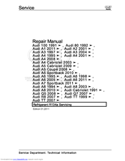
Audi TT 2007 Repair Manual (261 pages)
Edition 10.2009
Brand:
Audi
| Category:
Automobile
| Size: 8.87 MB
Table of Contents
Manual Transmission
1
Table of Contents
3
General, Technical Data
7
General Information
7
Location on Transmission
7
General Repair Information
8
Contact Corrosion
8
Repair Instructions
8
Overall Transmission Ratio I, Calculating
12
Description and Operation
13
Powertrain Overview
13
Specifications
15
Code Letters, Assembly Allocation, Ratios and Capacities
15
Clutch
17
General Information
17
Determining Clutch Manufacturer
17
Clutch System, Bleeding
18
Permitted Unless Authorised by AUDI AG. AUDI AG Does Not Guarantee or Accept any Liability
18
Clutch Master Cylinder and Clutch Slave Cylinder, Function Test
19
Description and Operation
21
Clutch Mechanism Overview
21
Pedal Assembly, Master Cylinder Assembly Overview
23
Hydraulics Assembly Overview
25
Clutch Release Mechanism, Clutch Slave Cylinder Assembly Overview
27
Sachs Clutch Assembly Overview
28
Luk Clutch Assembly Overview
31
Specifications
34
Fastener Tightening Specifications
34
Removal and Installation
35
Hose/Line Assembly or Plastic Line
35
Over-Center Spring
36
Clutch Pedal
38
Mounting Bracket
40
Clutch Position Sensor
42
Master Cylinder
43
Slave Cylinder with Release Bearing
45
Sachs Clutch
46
Luk Clutch
48
Special Tools
51
Controls, Housing
53
General Information
53
Manual Transmission, Checking Gear Oil Level
53
Gear Oil in Bevel Box, Checking
54
Gear Oil in Bevel Box, Filling
55
Description and Operation
58
Selector Mechanism Overview
58
Shift Knob and Covers Assembly Overview
60
Shift Lever and Shift Housing for Vehicles to VIN 8J-7-013000 Assembly Overview
62
Shift Lever and Shift Housing for Vehicles from VIN 8J-7-013001 Assembly Overview
65
Shift Cable and Selector Cable to Model Year 2007 Assembly Overview
67
Transmission Shift Lever and Selector Relay Lever to Model Year 2007 Assembly Overview
69
Shift Cable and Selector Cable from Model Year 2008 Assembly Overview
71
Shift Mechanism, Adjusting
75
Subframe Mount Assembly Overview
78
Transmission Overview
81
Transmission Assembly Overview
82
Transmission Housing and Shift Mechanism Assembly Overview
83
Input Shaft, Output Shafts, Differential, Bevel Box and Selector Rods Assembly Overview
85
Transmission Housing Assembly Overview
87
Clutch Housing Assembly Overview
89
Shift Mechanism Assembly Overview, Transmission Side
91
Shift Forks Assembly Overview
92
Specifications
93
Bevel Box Oil Filler Bolt
93
Manual Transmission Oil Filler Plug
93
Fastener Tightening Specifications
93
Removal and Installation
96
Shift Knob with Shift Lever Boot
96
Selector Mechanism
97
Shift Cable and Selector Cable
100
Transmission, Removing
102
Transmission, Transporting
112
Transmission, Securing to Assembly Stand
113
Transmission, Installing
113
Transmission Mount, Removing
119
Transmission Mount, Installing
122
Pendulum Support
123
Bevel Box, Removing
124
Bevel Box, Installing
128
Input Shaft Seal
129
Selector Shaft Seal
130
Selector Shaft
132
Disassembly and Assembly
134
Selector Mechanism
134
Transmission Without Circlip a for Cap/Input Shaft
137
Transmission with Circlip a for the Cap/Input Shaft
148
Shift Forks
158
Transmission Housing
158
Clutch Housing, Servicing
164
Special Tools
166
Gears, Shafts
183
General Information
183
Grooved Ball Bearing Changes
183
Description and Operation
185
Input Shaft Assembly Overview
185
Output Shaft for 1St to 4Th Gears Assembly Overview
187
Output Shaft, 1St to 4Th Gears, Adjusting
189
Output Shaft for 5Th/6Th Gear/Reverse Gear Assembly Overview
193
Output Shaft for 5Th/6Th Gear and Reverse Gear, Adjusting
194
Disassembly and Assembly
198
Input Shaft
198
Output Shaft, 1St to 4Th Gears
200
Output Shaft for 5Th/6Th Gear and Reverse Gear
208
Special Tools
214
Final Drive, Differential
225
Description and Operation
225
Flange Shaft and Seals on Transmission Assembly Overview
225
Flange Shaft and Seals on Bevel Box Assembly Overview
226
Differential Assembly Overview
228
Adjustment Overview
230
Differential, Adjusting
230
Permitted Unless Authorised by AUDI AG. AUDI AG Does Not Guarantee or Accept any Liability
231
Permitted Unless Authorised by AUDI AG. AUDI AG Does Not Guarantee or Accept any Liability
232
Specifications
233
Fastener Tightening Specifications
233
Permitted Unless Authorised by AUDI AG. AUDI AG Does Not Guarantee or Accept any Liability
233
Removal and Installation
234
Left Flange Shaft
234
Left Flange Shaft Seal
234
Shaft Sealing Ring for Bevel Box with Manual Transmission Installed, Replacing
235
Right Flange Shaft
236
Right Flange Shaft Seat on Outer Bevel Box, Replacing
237
Right Flange Shaft Needle Bearing
238
Seal between Transmission and Bevel Box
239
Bevel Box Drive Flange Seal
240
Disassembly and Assembly
244
Differential
244
Special Tools
248
Advertisement
Audi TT 2007 Repair Manual (211 pages)
Vehicle air conditioning systems
Brand:
Audi
| Category:
Air Conditioner
| Size: 1.94 MB
Table of Contents
Table of Contents
3
General, Technical Data
5
1 General Information
5
A/C System
5
Refrigerant Oil
11
Safety Precautions
12
Laws and Regulations
16
A/C System Principles
22
1.4 Refrigerant Circuit and Components
25
Refrigerant Circuit and Components
25
Component Replacement
26
Connections for Quick-Release Coupling on Refriger- Ant Circuit
28
O-Ring Seals
28
Refrigerant Circuit Connections with Valve for Switches
30
Refrigerant Circuit Pipes and Hoses
30
Refrigerant Circuit, Cleaning
31
Refrigerant Circuit, Converting R12 to R134A
31
Refrigerant Circuit, Flushing
32
Refrigerant Circuit Flushing with Compressed Air and Nitrogen
33
Refrigerant Circuit Flushing with Refrigerant R134A
36
Refrigerant Circuit, Repairing
43
Switches and Sensors
43
2 Description and Operation
45
Refrigerant Circuit
45
Refrigerant Circuit Precautions
45
Ball Valve
63
Pressure Relief Valve
72
Switches and Sensors on Refrigerant Circuit and Connections
78
Electrical Components Not on Refrigerant Circuit
82
2.4 A/C Service Station
83
A/C Service Station
83
Using Service Station
84
Charging Refrigerant Circuit
87
Connecting for Measuring and Testing, Two Service Connections
87
Connecting for Measuring and Testing, One Service Connection
88
Connecting for Measuring and Testing, no Service Connection
89
Connecting with Air Conditioning Adapter Set V.A.G 1786
90
Connecting with Adapter Set VAG1785/10
91
Draining Refrigerant Circuit
91
Draining Service Station
92
Evacuating Refrigerant Circuit
93
Transferring Refrigerant to Reservoir (Charging Cylinder or Reservoir Bottle) of Service Station
97
3 Specifications
98
Charging Refrigerant
98
Refrigerant R134A Capacities
98
Capacities, Audi A3 (8L_) 1997 through MY 2004 and Audi TT (8N_), from MY 1999
100
Capacities, Audi A3 (8P_) from MY 04
103
Capacities, Audi TT (8J_) from MY 07
104
Capacities, Audi 80 (8A_/8C_), Audi Coupe (8B_) and Audi Cabriolet (8G_), from MY 2002
105
Capacities, Audi A4 (8D_), from MY 95
105
Audi A5 Cabriolet (8F_) from MY 2009
109
Capacities, Audi A4 (8K_) from MY 2008, Audi A5
109
Capacities, Audi 100 and Audi A6 (4A_), from MY 98
110
Capacities, Audi A6 (4B_) from MY 1998 and Audi Allroad (4B_) from MY 2005
111
Capacities, Audi A6 (4F_), from MY 05
116
Capacities, Audi V8 (4C_) from MY 94
117
Capacities, Audi A8 (4D_) from MY 94
118
Capacities, Audi A8 (4E_) from MY 03
119
Capacities, Audi A8 (4H_) from MY 10
119
Features of the Refrigerant System
119
Refrigerant Oils
121
3.4 Refrigerant Oil Capacities
123
Refrigerant Oil Capacities
123
At Start of Production, A/C Compressors Manufactured by
125
Led. Refer to Electronic Parts Catalog (ETKA) and ⇒ Heating
125
Ventilation and Air Conditioning; Rep. Gr. 87 ; Removal and
125
Depending on the Engine, an A/C Compressor Manufactured
125
Time (Introduction Still Open). Refer to Electronic Parts Catalog
125
(ETKA) and ⇒ Heating, Ventilation and Air Conditioning; Rep
125
Gr. 87 ; Removal and Installation
125
Capacities, Audi A2 (8Z_) from MY 01
125
Restrictor (Colored)
125
Removal and Installation
126
Capacities, Audi A3 (8L_) 1997 through MY 2004 and Audi TT (8N_), from MY 1999
126
Capacities, Audi A3 (8P_) from MY 04
127
Capacities, Audi TT (8J_) from MY 07
128
Capacities, Audi 80 (8A_/8C_), Audi Coupe (8B_) and Audi Cabriolet (8G_), from MY 2002
129
3.4.7 Capacities, Audi A4 (8D_), from My 95
130
Vehicle Mod-Production Period Total Quantity of Oil in Refrig-Quantity of Refrigerant Oil in Replace- el Erant Circuit in CM 3 Ment Compressor in CM
133
As of 04.97
134
The Replacement Compressor Contains the Full Quantity of Oil
134
Intended for the Refrigerant Circuit. on A/C Compressor Re
134
Placement, the Quantity of Oil in the A/C Compressor Is There
134
Fore to be Adjusted. Refer to
134
Beginning the Production Year 2006, the Name of the Zexel a
134
C Compressor was Changed from Zexel to Valeo
134
Vehicle Mod-Production Period Total Quantity of Oil in Refrig-Quantity of Refrigerant Oil in Replace- el Erant Circuit in CM 3 Ment Compressor in CM
136
As of
141
4 Diagnosis and Testing
146
Pressure Gauge, Tests and Measurements
146
Leak Detection
147
Refrigerant Circuit Concerns
155
Pressures, Checking
157
5 Removal and Installation
195
Leaking or Damaged Components Except A/C Compressor, Accumulator or Receiver - Circuit Empty of Refrigerant
195
Leaking or Damaged Components Except A/C Compressor, Accumulator or Receiver - Circuit Contains Refrigerant
197
Compressor, Replacing Without Flushing Refrigerant Circuit
197
Compressor, Replacing Due to Leakage or Internal Damage
198
Receiver or Accumulator and Restrictor, Replacing after Cleaning Refrigerant Circuit
199
Receiver or Accumulator, Replacing Without Flushing Refrigerant Circuit
200
Dryer Cartridge and Dryer Bag, Replacing Without Flushing Refrigerant Circuit
201
6 Special Tools
202
Commercially Available Tools and Materials
202
Improvised Tools
207
Audi TT 2007 Workshop Manual (106 pages)
Brand:
Audi
| Category:
Automobile
| Size: 2.64 MB
Table of Contents
Table of Contents
3
Technical Data
5
Gearbox Identification
5
Code Letters, Gearbox Allocation, Ratios, Equipment
6
Calculating Ratio "I
6
Capacities
7
Safety Precautions
8
Notes on the Direct Shift Gearbox 02E
9
General Notes
9
Safety Functions of Gearbox Control Unit
9
Notes on Tow-Starting and Towing
11
Repair Instructions
12
Rules for Cleanliness
14
Clutch
15
Servicing Multiple Clutch - Exploded View
15
Removing and Installing Multiple Clutch
17
Controls, Housing
27
Selector Lever Handle, Selector Lever Display Illumination Bulb L101 - Exploded View
30
Removing and Installing Selector Lever Handle
30
Removing and Installing Selector Lever Display Illumination Bulb L101
32
Servicing Selector Mechanism - Exploded View
34
Manual Release of Selector Mechanism
35
Checking Selector Mechanism and Ignition Key Removal Lock
36
Removing and Installing Selector Mechanism
37
Removing and Installing Selector Lever Cable
40
Adjusting Selector Lever Cable
44
Removing and Installing Tiptronic Switch F189
45
Removing and Installing Selector Lever Lock Solenoid N110
46
Checking Connectors on Selector Mechanism
46
Removing Gearbox
47
Installing Gearbox
57
Tightening Torques (Installing Gearbox)
59
Transporting the Direct Shift Gearbox
60
Securing Gearbox to Assembly Stand
61
Assembly Mountings - Exploded View
63
Removing and Installing Gearbox Mounting
65
Removing and Installing Pendulum Support
68
Checking Gear Oil Level and Topping up
70
Changing Gear Oil or Filling up after Performing Repairs
76
Gear Oil Cooler and Gear Oil Filter - Exploded View
80
Removing and Installing Gear Oil Cooler
80
Removing and Installing Gear Oil Filter
82
Gears, Shafts
84
Oil Pan, Mechatronic Unit, Gear Oil Pump - Exploded View
84
Oil Pan, Mechatronic Unit, Gear Oil Pump
84
Removing and Installing Oil Pan
86
Removing and Installing Mechatronic Unit for Direct Shift Gearbox J743
89
Removing and Installing Gearbox Input Speed Sender G182 and Clutch Temperature Sender G509
93
Removing and Installing Gear Oil Pump
94
Final Drive - Differential
97
Flange Shafts and Oil Seals - Exploded View
97
Removing and Installing Flange Shaft (Left-Side)
98
Removing and Installing Flange Shaft (Right-Side)
99
Renewing Oil Seal for Flange Shaft (Left-Side)
101
Renewing Oil Seal for Flange Shaft (Right-Side)
102
Renewing Oil Seal for Selector Shaft
104
Advertisement
Audi TT 2007 Repair Manual (69 pages)
Brand:
Audi
| Category:
Automobile
| Size: 2.04 MB
Table of Contents
Table of Contents
3
Maintenance Procedures
1
Maintenance, Diagnosis
5
General Information
5
Engine Overview
5
Type Plate and VIN
8
Raising Vehicle
10
Tow Starting/Towing
11
Vehicle Checks During Inspection and Maintenance
13
Tachometer Check
14
Maintenance Procedures
16
2.1 Strut Tube Cap, Lubricating
17
Strut Tube Cap, Lubricating
17
Battery, Checking Level Using Guided Fault Finding
18
Measured Values Block 32, Reading
18
Battery, Checking no Load Voltage before Starting Engine
19
Battery, Check Fluid Level
21
AGM Battery, Checking
23
Battery, Checking Cables for Secure Seating
24
Tires, Checking
24
Spare Tire
25
Brake Pads, Checking Thickness
26
Brake System, Inspecting for Leaks and Damage
26
Brake Fluid, Checking Depending on Brake Pad Wear
27
Brake Fluid, Changing
28
Fuel Injector Cleaner G17
31
DTC Memory, Checking
32
Engine Compartment Front Noise Insulation Cover, Removing and Installing
32
Key, Check Functionality
32
Coolant System, Checking
33
Instrument Cluster, Selecting Language
34
Air Filter, Cleaning Housing and Removing and Installing Filter
35
Engine Cover, Removing
41
Haldex Clutch Oil, Changing
41
Hood Safety Catch, Lubricating
41
Engine and Engine Compartment from Underneath, Inspecting for Leaks and Damage
43
Engine Oil, Draining/Extracting and Removing and Installing Filter
44
Engine Oil, Filling
47
Hood Hinge, Lubricating
47
Engine Oil Level, Checking
48
Navigation Eject Button, Unlocking
48
Radio, Entering Security Code to Activate Anti-Theft Coding
48
With Respect to the Correctness of Information in this Document. Copyright by AUDI AG
48
Road Test
49
With Respect to the Correctness of Information in this Document. Copyright by AUDI AG
49
Tire Pressure Monitoring Display, Adapting
50
Wheel Bolts, Tightening Specifications
50
Windshield Washer System, Checking and Adjusting Spray Nozzles
50
Headlamp Washer System, Checking Spray Nozzles
53
Service Display, Resetting or Adapting
53
Windshield Wiper Blades, Checking End Position and for Damage
53
Install Fuse for Headlamp Washer System
56
Dust and Pollen Filter, Removing and Installing
57
Tie Rods, Control Arms, Ball Joint and Driveshafts, Checking Play, Fit and Sealing Boots
58
Transport Mode, Deactivating Using VAS 5051/5052
58
Door Arrester, Door Hinge and Lock Cylinder, Lubricat- Ing
59
Door Arrester, Door Hinge and Lock Cylinder, Lubricating
59
Factory-Equipped Winter Tires
60
Plenum Chamber Water Drain, Checking and Cleaning
60
Transport Protection, Removing Front and Rear Suspen- Sion Strut Protectors
60
Transport Protection, Removing Front and Rear Suspension Strut Protectors
60
Underbody Protection, Inspecting for Damage
60
Clock, Setting
61
Spark Plugs, Removing and Installing
61
Advertisement
Related Products
Audi TT 2012
Audi TT 2015
Audi TT 207
Audi TT 2019
Audi TT 2011
Audi TT 2010
Audi TT 2014
AUDI TTS -
Audi TT 1999
Audi TT RS
Audi Categories
Automobile
Automobile Accessories
Engine
Car Navigation system
Motorized Toy Car
More Audi Manuals
Login
Sign In
OR
Sign in with Facebook
Sign in with Google
Upload manual
Upload from disk
Upload from URL