Sign In
Upload
Manuals
Brands
ARM Manuals
Computer Hardware
DSTREAM-HT
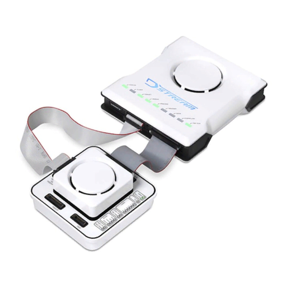
ARM DSTREAM-HT Manuals
Manuals and User Guides for ARM DSTREAM-HT. We have
2
ARM DSTREAM-HT manuals available for free PDF download: Reference Manual, Getting Started Manual
ARM DSTREAM-HT Reference Manual (60 pages)
System and Interface Design
Brand:
ARM
| Category:
Computer Hardware
| Size: 0 MB
Table of Contents
Copyright © 2019 Arm Limited or Its Affiliates. All Rights Reserved
2
Table of Contents
4
About this Book
10
Chapter 1 Debug and Trace Interface
10
Preface
10
Table
11
Figure 1-1 Simple JTAG Connection
13
JTAG Signals
13
Figure 1-2 Chained JTAG Connection
14
JTAG Timing Characteristics
14
Figure 1-3 JTAG Timing Diagram
15
Figure 1-4 Basic JTAG Port Synchronizer
16
Figure 1-5 Timing Diagram for the Basic JTAG Synchronizer
16
Figure 1-6 JTAG Port Synchronizer for Single Rising-Edge D-Type ASIC Design Rules
16
Figure 1-7 Timing Diagram for the D-Type JTAG Synchronizer
17
Return Clock (RTCK) Signal
18
Reset Signals
19
Figure 1-8 Example Reset Circuit
20
Run-Control Signals
21
Figure 1-9 SWD Timing Diagrams
22
Serial Wire Debug (SWD) Signals
22
SWD Timing Requirements
22
Trace Signals
24
Figure 1-10 TRACECLK Timing Diagram
25
Table 1-3 TRACECLK Characteristics
25
Target Voltage Reference (VTREF) Signals
26
Figure 1-11 Target Interface Logic Levels
27
Figure 1-12 Input/Output Signals
28
Figure 1-13 TCK Signal
28
Figure 1-14 Reset Signals
28
I/O Diagrams for DSTREAM-HT Signals
28
Figure 1-15 Parallel Trace Signals
29
Figure 1-16 HSSTP Trace Signals
29
Figure 1-17 VTREF Signals
29
Figure 1-18 Typical SWD Circuit
30
Typical SWD Circuit
30
Figure 1-19 Typical JTAG Circuit
31
Typical JTAG Circuit
31
Table 2-1 Connector Attributes
34
Target Connector Selection Guide
34
Arm JTAG 20 Connector
35
Arm JTAG 20 Pinout Table
35
Figure 2-1 Arm JTAG 20 Connector Pinout
35
10 Connector
36
Figure 2-2 Coresight 10 Connector Pinout
36
Table 2-3 Arm Coresight 10 Pinout Table
36
20 Connector
37
Arm Coresight 20 Pinout Table (DSTREAMCS20=0)
37
Figure 2-3 Coresight 20 Connector Pinout
37
Arm Coresight 20 Pinout Table (DSTREAMCS20=1)
38
Figure 2-4 TI JTAG 14 Connector Pinout
39
TI JTAG 14 Connector
39
TI JTAG 14 Pinout Table
39
Figure 2-5 Mictor 38 Connector Pinout
40
Mictor 38 Connector
40
Mictor 38 Pinout Table
40
Figure 2-6 MIPI 34 Connector Pinout
42
MIPI 34 Connector
42
MIPI 34 Pinout Table
42
Figure 2-7 MIPI 60 Connector Pinout
44
MIPI 60 Connector
44
MIPI 60 Pinout Table
44
Figure 2-8 HSSTP 40 Connector Pinout
46
HSSTP 40 Connector
46
HSSTP 40 Pinout Table
46
Auxiliary (AUX) Connector
48
Figure 2-9 User I/O Connector Pinout
49
User I/O Connector
49
User I/O Pinout Table
49
Figure 3-1 Point-To-Point Signal
51
Figure 3-2 Stub Length
51
Overview of High-Speed Design
51
Figure 3-3 Long Stub Causing False Edges
52
Figure 3-4 Improved Route with Shorter Stub
52
Figure 3-5 JTAG Connection Without Buffers
54
Figure 3-6 JTAG Connection with TDO Buffer
54
Figure 3-7 Daisy-Chained JTAG Connection Without Buffers
54
JTAG Port Buffering
54
Figure 3-8 Daisy-Chained JTAG Connection with TCK Buffers
55
Figure 3-9 Fully Buffered JTAG Connection
55
Series Termination
57
Table 3-1 Typical Series Terminating Resistor Values
57
Parallel Trace Modeling
58
Target Design Checklist
59
Advertisement
ARM DSTREAM-HT Getting Started Manual (39 pages)
Brand:
ARM
| Category:
Computer Hardware
| Size: 1 MB
Table of Contents
Table of Contents
6
List of Figures
7
Introduction
8
Conventions
8
Useful Resources
9
Other Information
9
The DSTREAM-HT System
10
Buy Arm DSTREAM-HT
11
Arm DSTREAM-HT Box Contents
11
Figure 2-1: DSTREAM-ST Unit
11
Figure 2-2: HSSTP Trace Probe
11
Figure 2-3: DSTREAM-HT Power Supply and Cables
12
Figure 2-4: 60-Way Auxiliary (AUX) Host Port Cable
12
Figure 2-5: Coresight 10/20-Way 0.05" Pitch Ribbon Cable
12
Figure 2-6: Coresight Short 20-Way 0.05" Pitch Ribbon Cable
12
Figure 2-7: JTAG 20-Way 0.1" Pitch Ribbon Cable
13
Figure 2-8: HSSTP 40-Way Co-Axial Ribbon Cable
13
Figure 2-9: JTAG 14-Way Texas Instruments Adapter
13
Figure 2-10: MICTOR 38-Way 4-Bit Adapter
13
The DSTREAM-ST Unit
14
Figure 2-11: Rear of the DSTREAM-ST Unit
14
Figure 2-12: Front of the DSTREAM-ST Unit
16
Figure 2-13: Indicator Leds
17
The HSSTP Probe
19
Figure 2-14: Rear of HSSTP Trace Probe
19
Figure 2-15: Top of HSSTP Trace Probe
20
Set up Your DSTREAM-HT
23
Install the USB Drivers for the DSTREAM-HT System on Windows
23
Install the USB Drivers for the DSTREAM-HT System on Linux
24
Connect and Power up the DSTREAM-HT System
24
Figure 3-1: DSTREAM-HT Connection
27
Figure 3-2: DSTREAM-HT Debug Bypass Connection
27
DSTREAM-HT System Boot Sequence
28
Update the DSTREAM-HT System Firmware
29
Work with Your DSTREAM-HT
31
Debug Software for DSTREAM-HT
31
Hot-Plug the Debug Cable
32
Troubleshooting
34
HSSTP Probe LED Errors
34
Host Link Issues
36
DSTREAM-HT Overheats
37
Arm Development Studio Invalid Trace
37
Restore a DSTREAM-HT System
38
Remotely Restart a DSTREAM-HT System
39
Advertisement
Related Products
ARM DSTREAM
ARM DSTREAM-XT
ARM DSTREAM-PT
ARM DSTREAM-ST
ARM DSTREAM DS-5
ARM Developer Suite
ARM ARM1176JZF-S
ARM ARM710T
ARM ARM7TDMI
ARM ARM926EJ-S
ARM Categories
Computer Hardware
Motherboard
Controller
Processor
Computer Accessories
More ARM Manuals
Login
Sign In
OR
Sign in with Facebook
Sign in with Google
Upload manual
Upload from disk
Upload from URL