Sign In
Upload
Manuals
Brands
Allied Telesis Manuals
Switch
AlliedWare Plus x530 Series
Allied Telesis AlliedWare Plus x530 Series Manuals
Manuals and User Guides for Allied Telesis AlliedWare Plus x530 Series. We have
2
Allied Telesis AlliedWare Plus x530 Series manuals available for free PDF download: Installation Manual
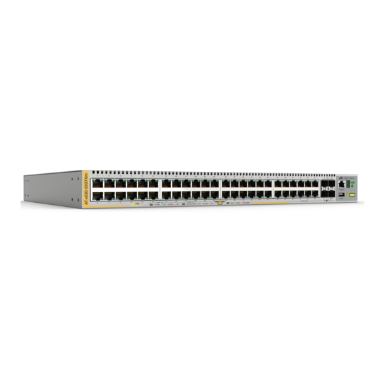
Allied Telesis AlliedWare Plus x530 Series Installation Manual (120 pages)
Stand-alone Stackable Gigabit Layer 3+ Ethernet Switches
Brand:
Allied Telesis
| Category:
Switch
| Size: 6.48 MB
Table of Contents
Table of Contents
5
Preface
11
Document Conventions
12
Contacting Allied Telesis
13
Chapter 1: Overview
15
Front and Rear Panels
16
Figure 1: Front Panel of the AT-X530-28Gtxm Switch
16
Figure 2: Front Panel of the AT-X530-28Gpxm Switch
16
Figure 3: Front Panel of the AT-X530-52Gtxm Switch
16
Figure 4: Front Panel of the AT-X530-52Gpxm Switch
17
Figure 5: Back Panel of the AT-X530-28Gtxm, AT-X530-28Gpxm, AT-X530-52Gtxm, and AT-X530-52Gpxm Switches
17
Management Panel
18
Figure 6: Management Panel
18
Features
19
X530 Models
19
Table 1: Basic Features
19
Twisted Pair Ports
20
Table 2: Twisted Pair Port Features
20
Power over Ethernet
21
SFP+ Transceiver Ports
21
Leds
22
Installation Options
22
Management Software and Interfaces
22
Management Methods
22
Twisted Pair Ports
23
Table 3: AT-X530-28Gtxm Switch Twisted Pair Port Specifications
23
Table 4: AT-X530-28Gpxm Switch Twisted Pair Port Specifications
24
Table 5: AT-X530-52Gtxm Switch Twisted Pair Port Specifications
25
Speed
26
Table 6: AT-X530-52Gpxm Switch Twisted Pair Port Specifications
26
Duplex Mode
27
Wiring Configuration
27
Maximum Distance
27
Cable Requirements
28
Leds
28
AT-X530-28Gtxm and AT-X530-52Gtxm
28
Figure 7: AT-X530-28Gtxm and AT-X530-52Gtxm Twisted Pair Ports Leds
28
Table 7: AT-X530-28Gtxm Twisted Pair Ports 1 - 24 LED Functions
29
Table 8: AT-X530-52Gtxm Twisted Pair Ports 1 - 48 LED Functions
30
AT-X530-28Gpxm and AT-X530-52Gpxm
31
Figure 8: AT-X530-28Gpxm and AT-X530-52Gpxmtwisted Pair Ports Leds
31
Table 9: AT-X530-28Gpxm Twisted Pair Ports 1 - 24 LED Functions
31
Table 10: AT-X530-52Gpxm Twisted Pair Ports 1 - 48 LED Functions
33
Power over Ethernet
34
Poe Standards
34
Powered Device Classes
35
Power Budget
35
Port Prioritization
35
Table 11: IEEE Powered Device Classes
35
Wiring Implementation
36
SFP+ Transceiver Ports
37
SFP and SFP+ Transceivers
37
Leds
37
Figure 9: Link and Activity Leds for the 1 Gbps/10 Gbps SFP+ Ports
37
Table 12: Link and Activity Status Leds for the 1 Gbps and 10 Gbps Ports
38
Eco-Friendly Button
39
Vcstack Feature
40
Switch ID LED
41
Figure 10: Switch ID LED
41
Figure 11: Switch ID LED Description
42
USB Port
43
Console Port
44
Power Supply
45
Software and Hardware Releases
46
Table 13: Software and Hardware Releases
46
Chapter 2: Beginning the Installation
47
Reviewing Safety Precautions
48
Choosing a Site for the Switch
52
Unpacking the Switch
53
Figure 12: Switch Shipping Box
53
Figure 13: Accessory Kit Items
54
Chapter 3: Installing the Switch on a Table
55
Figure 14: Parts of the Bumper Feet
55
Figure 15: Holes for Bumper Feet
56
Figure 16: Inserting the Rivet Housing into the Bumper Foot
56
Figure 17: Placing the Bumper Foot on a Base Corner Hole
57
Figure 18: Inserting the Rivet into the Bumper Foot
57
Chapter 4: Installing the Switch in an Equipment Rack
59
Beginning the Installation
60
Required Items
60
Switch Orientations in the Equipment Rack
60
Figure 19: Bracket Holes on the Switch
60
Figure 20: Switch Orientations in an Equipment Rack
61
Removing the Bumper Feet
62
Figure 21: Removing the Bumper Feet
62
Installing the Switch
63
Figure 22: Example of Attaching the Brackets to the Switch
63
Figure 23: Installing the Switch in an Equipment Rack
64
Chapter 5: Installing the Switch on a Wall
65
Switch Orientations on a Wall
66
Figure 24: Positioning the AT-X530-28Gtxm or AT-X530-52Gtxm Switch on the Wall
66
Figure 25: Positioning the AT-X530-28Gpxm or AT-X530-52Gpxm Switch on the Wall
67
Installation Guidelines
68
Tools and Material
69
Plywood Base for a Wall with Wooden Studs
71
Figure 26: Switch on the Wall with a Plywood Base
71
Figure 27: Installing the Plywood Base to the Wall
72
Figure 28: Installing the Switch on the Plywood Base
73
Installing a Plywood Base
74
Installing the Switch on a Plywood Base
75
Figure 29: Installing Two Brackets on the AT-X530-28Gtxm or AT-X530-52Gtxm Switch
76
Figure 30: Installing Four Brackets on the AT-X530-28Gpxm or AT-X530-52Gpxm Switch
77
Figure 31: Securing the AT-X530-28Gtxm or AT-X530-52Gtxm Switch to the Plywood Base
78
Figure 32: Securing the AT-X530-28Gpxm or AT-X530-52Gpxm Switch to the Plywood Base
79
Installing the Switch on a Concrete Wall
80
Figure 33: Marking the Locations of the Bracket Holes on a Concrete Wall
81
Figure 34: Installing the Switch on a Concrete Wall
82
Chapter 6: Powering on the Switch
83
Powering on the Switch
84
Figure 35: Installing the Power Cord Retaining Clip
84
Figure 36: Connecting the AC Power Cords
85
Figure 37: Lowering the Power Cord Retaining Clips
85
Figure 38: Connecting the Power Cords to an AC Power Source
86
Monitoring the Initialization Processes
87
Figure 39: Switch Initialization Messages
87
Figure 40: Switch Initialization Messages (Continued)
88
Figure 41: Switch Initialization Messages (Continued)
89
Chapter 7: Configuring the Switch for Stand-Alone Operations
91
Determining the Stand-Alone or Stacking Status of the Switch
92
Starting a Local Management Session
93
Figure 42: Connecting the Management Cable to the Console Port
93
Disabling the Vcstack Feature
95
Figure 43: SHOW STACK Command
95
Figure 44: Moving to the Global Configuration Mode
96
Figure 45: Disabling Vcstack
96
Saving Your Changes and Rebooting the Switch
97
Figure 46: Returning to the Privileged Exec Mode
97
Figure 47: Saving the Changes with the WRITE Command
97
Specifying Ports in the Command Line Interface for Stand-Alone Switches
98
Figure 48: PORT Parameter in the Command Line Interface
98
Table 14: PORT Parameter Format
98
Chapter 8: Cabling the Networking Ports
99
Cabling Twisted Pair Ports
100
Guidelines to Handling SFP and SFP+ Transceivers
101
Installing SFP or SFP+ Transceivers in the Switch
102
Figure 49: Installing an SFP Transceiver
102
Figure 50: Positioning the SFP or SFP+ Handle in the Upright Position
103
Figure 51: Connecting a Fiber Optic Cable to an SFP or SFP+ Transceiver
103
Installing AT-SP10TW Direct Connect Twinax Cables
104
Figure 52: Installing AT-SP10TW Cables
105
Chapter 9: Troubleshooting
107
Technical Specifications
111
Physical Specifications
112
Dimensions
112
Table 15: Product Dimensions
112
Weights
114
Ventilation
114
Table 16: Product Weights
114
Table 17: Ventilation Requirements
114
Environmental Specifications
115
Figure 53: RJ-45 Socket Pin Layout (Front View)
115
Table 18: Environmental Specifications
115
Power Specifications
116
Maximum Power Consumption
116
Input Voltages
116
Heat Dissipation
116
Table 19: Maximum Power Consumptions
116
Table 20: Input Voltages
116
Table 21: Heat Dissipation
116
RJ-45 Twisted Pair Port Pinouts
117
Table 22: Pin Signals for 100M/1G/2.5G/5G Base-T Connectors
117
RJ-45 Style Serial Console Port Pinouts
118
Table 23: RJ-45 Style Serial Console Port Pin Signals
118
USB Port
119
Table 24: USB Port Pin Signals
119
Advertisement
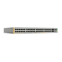
Allied Telesis AlliedWare Plus x530 Series Installation Manual (110 pages)
Stand-alone Switches, Stackable Gigabit Layer 3+ Ethernet Switches v5.4.8-2
Brand:
Allied Telesis
| Category:
Switch
| Size: 4.07 MB
Table of Contents
Table of Contents
5
Preface
11
Document Conventions
12
Contacting Allied Telesis
13
Chapter 1: Overview
15
Front and Rear Panels
16
Figure 1: Front Panels of the X530 Series Switches
16
Figure 2: Back Panels of the X530 Series Switches
17
Management Panel
18
Figure 3: Management Panel
18
Features
19
X530 Models
19
Twisted Pair Ports
19
Table 1: Basic Features
19
Power over Ethernet
20
SFP+ Transceiver Slots
20
Leds
20
Installation Options
21
Management Software and Interfaces
21
Management Methods
21
Twisted Pair Ports
22
Table 2: AT-X530-28Gtxm Switch Twisted Pair Port Specifications
22
Table 3: AT-X530-28Gpxm Switch Twisted Pair Port Specifications
22
Duplex Mode
23
Speed
23
Wiring Configuration
23
Cable Requirements
24
Maximum Distance
24
Table 4: Cable Requirements for Ports 1 - 24 at 100 Mbps or 1 Gbps
24
Figure 4: AT-X530-28Gtxm Twisted Pair Ports 1-24 Leds
25
Leds
25
Port Pinouts
25
Table 5: AT-X530-28Gtxm Twisted Pair Ports 1 - 24 LED Functions
25
Figure 5: AT-X530-28Gpxm Twisted Pair Ports 1-24 Leds
26
Table 6: AT-X530-28Gpxm Twisted Pair Ports 1 - 24 LED Functions
26
Power over Ethernet on the AT-X530-28Gpxm Switch
28
Poe Standards
28
Powered Device Classes
29
Power Budget
29
Port Prioritization
29
Table 7: IEEE Powered Device Classes
29
Wiring Implementation
30
SFP+ Transceiver Slots on the AT-X530-28Gtxm and AT-X530-28Gpxm Switches
31
SFP and SFP+ Transceivers
31
Leds
31
Figure 6: Link and Activity Leds for the 1 Gbps/10 Gbps SFP+ Slots
31
Table 8: Link and Activity Status Leds for the 1 Gbps and 10 Gbps Ports
32
Eco-Friendly Button
33
Vcstack Feature
34
Switch ID LED
35
Figure 7: Switch ID LED
35
Figure 8: Switch ID LED Description
36
USB Port
37
Console Port
38
Power Supply
39
Chapter 2: Beginning the Installation
41
Reviewing Safety Precautions
42
Choosing a Site for the Switch
46
Unpacking the AT-X530-28Gtxm or AT-X530-28Gpxm Switch
47
Figure 9: AT-X530-28Gtxm or AT-X530-28Gpxm Switch Shipping Box
47
Figure 10: Accessory Kit Items
48
Chapter 3: Installing the Switch on a Table
49
Figure 11: Parts of the Bumper Feet
49
Figure 12: Holes for Bumper Feet
50
Figure 13: Inserting the Rivet Housing into the Bumper Foot
50
Figure 14: Placing the Bumper Foot on a Base Corner Hole
51
Figure 15: Inserting the Rivet into the Bumper Foot
51
Chapter 4: Installing the Switch in an Equipment Rack
53
Installing AT-X530-28Gtxm or AT-X530-28Gpxm Switches in an Equipment Rack
54
Required Items
54
Switch Orientations in the Equipment Rack
54
Figure 16: Bracket Holes on the AT-X530-28Gtxm and AT-X530-28Gpxm Switches
54
Installing the Switch
55
Figure 17: Switch Orientations in an Equipment Rack
55
Figure 18: Example of Attaching the Brackets to the Switch
56
Figure 19: Installing the Switch in an Equipment Rack
57
Chapter 5: Installing the Switch on a Wall
59
Switch Orientations on a Wall
60
Figure 20: Positioning the AT-X530-28Gtxm Switch on the Wall
60
Figure 21: Positioning the AT-X530-28Gpxm Switch on the Wall
61
Installation Guidelines
62
Tools and Material
63
Plywood Base for a Wall with Wooden Studs
64
Figure 22: Installing the Plywood Base to the Wall
65
Figure 23: Installing the Switch on the Plywood Base
66
Installing a Plywood Base
67
Installing the Switch on a Plywood Base
68
Figure 24: Installing Two Brackets on the AT-X530-28Gtxm Switch
69
Figure 25: Installing Four Brackets on the AT-X530-28Gpxm Switch
70
Figure 26: Securing the AT-X530-28Gtxm Switch to the Plywood Base
71
Figure 27: Securing the AT-X530-28Gpxm Switch to the Plywood Base
72
Installing the Switch on a Concrete Wall
73
Figure 28: Marking the Locations of the Bracket Holes on a Concrete Wall
74
Figure 29: Installing the Switch on a Concrete Wall
75
Chapter 6: Powering on the Switch
77
Powering on the Switch
78
Figure 30: Installing the Power Cord Retaining Clip
78
Figure 31: Connecting the AC Power Cords
79
Figure 32: Lowering the Power Cord Retaining Clips
79
Figure 33: Connecting the Power Cords to an AC Power Source
80
Monitoring the Initialization Processes
81
Figure 34: Switch Initialization Messages
81
Figure 35: Switch Initialization Messages (Continued)
82
Figure 36: Switch Initialization Messages (Continued)
83
Chapter 7: Configuring the Switch for Stand-Alone Operations
85
Determining the Stand-Alone or Stacking Status of the Switch
86
Starting a Local Management Session
87
Figure 37: Connecting the Management Cable to the Console Port
87
Disabling the Vcstack Feature
89
Figure 38: SHOW STACK Command
89
Figure 39: Moving to the Global Configuration Mode
90
Figure 40: Disabling Vcstack
90
Saving Your Changes and Rebooting the Switch
91
Figure 41: Returning to the Privileged Exec Mode
91
Figure 42: Saving the Changes with the WRITE Command
91
Specifying Ports in the Command Line Interface for Stand-Alone Switches
92
Figure 43: PORT Parameter in the Command Line Interface
92
Table 9: PORT Parameter Format
92
Chapter 8: Cabling the Networking Ports
93
Cabling Twisted Pair Ports
94
Guidelines to Handling SFP and SFP+ Transceivers
95
Installing SFP or SFP+ Transceivers in AT-X530-28Gtxm and AT-X530-28Gpxm Switches
96
Figure 44: Removing the Dust Plug from an SFP Slot
96
Figure 45: Installing an SFP Transceiver
97
Figure 46: Removing the Dust Cover from an SFP or SFP+ Transceiver
97
Figure 47: Positioning the SFP or SFP+ Handle in the Upright Position
98
Figure 48: Connecting a Fiber Optic Cable to an SFP or SFP+ Transceiver
98
Chapter 9: Troubleshooting
99
Appendix A: Technical Specifications
103
Physical Specifications
104
Table 10: Product Dimensions
104
Table 11: Product Weights
104
Table 12: Ventilation Requirements
104
Environmental Specifications
105
Table 13: Environmental Specifications
105
Power Specifications
106
Table 14: Maximum Power Consumptions
106
Table 15: Input Voltages
106
Table 16: Heat Dissipation
106
Certifications
107
Table 17: Product Certifications
107
RJ-45 Twisted Pair Port Pinouts
108
Figure 49: RJ-45 Socket Pin Layout (Front View)
108
Table 18: Pin Signals for 100M/1G/2.5G/5G Base-T Connectors
108
RJ-45 Style Serial Console Port Pinouts
109
Table 19: RJ-45 Style Serial Console Port Pin Signals
109
USB Port
110
Table 20: USB Port Pin Signals
110
Advertisement
Related Products
Allied Telesis AlliedWare Plus x220 Series
Allied Telesis AlliedWare Plus x950 Series
Allied Telesis AlliedWare Plus x530DP Series
Allied Telesis AlliedWare Plus x530DP-28GHXm
Allied Telesis AlliedWare Plus x530DP-52GHXm
Allied Telesis AlliedWare Plus AT-x530-28GPXm
Allied Telesis AlliedWare Plus AT-PWR600
Allied Telesis AlliedWare Plus GS980MX/18HSm
Allied Telesis AlliedWare Plus GS980MX/28
Allied Telesis AlliedWare Plus GS980MX/28PSm
Allied Telesis Categories
Switch
Network Router
Media Converter
Network Hardware
Wireless Access Point
More Allied Telesis Manuals
Login
Sign In
OR
Sign in with Facebook
Sign in with Google
Upload manual
Upload from disk
Upload from URL