Sign In
Upload
Manuals
Brands
Aerotech Manuals
Industrial Equipment
ATX165SL
Aerotech ATX165SL Manuals
Manuals and User Guides for Aerotech ATX165SL. We have
1
Aerotech ATX165SL manual available for free PDF download: Hardware Manual
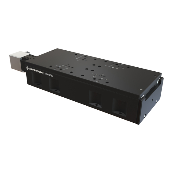
Aerotech ATX165SL Hardware Manual (64 pages)
Mechanical-Bearing, Screw-Driven Linear Stage
Brand:
Aerotech
| Category:
Industrial Equipment
| Size: 12.05 MB
Table of Contents
ATX165SL and SLE Mechanical-Bearing, Screw-Driven Linear Stage
1
Table of Contents
3
List of Figures
4
List of Tables
5
EU Declaration of Incorporation
6
UKCA Declaration of Incorporation
7
Safety Procedures and Warnings
8
Installation and Operation
9
Electrical Warnings
10
Motor-Related Warnings
11
Pinch Points
12
Handling and Storage
13
Chapter 1: Overview
15
Table 1-1: Model Numbers and Ordering Options
15
Environmental Specifications
16
Table 1-2: Environmental Specifications
16
Accuracy and Temperature Effects
17
Basic Specifications
18
Table 1-3: ATX165SL/SLE Series Specifications
18
Chapter 2: Installation
19
Dimensions
19
Figure 2-1: ATX165SL/SLE Dimensions
19
Figure 2-2: ATX165SL/SLE Mounting Plate Dimensions
20
Securing the Stage to the Mounting Surface
21
Table 2-1: Stage Mounting Surface Flatness Requirement
21
Table 2-2: Stage to Mounting Surface Hardware
21
Attaching the Payload to the Stage
22
Table 2-3: Payload Mounting Surface Flatness Requirement
22
Figure 2-3: Stage Orientations
23
Figure 2-4: Cantilevered Load Capability
24
Figure 2-5: Load Torque Equation
25
Figure 2-6: Torque Required to Turn Ball Screw in Vertical Orientation
25
Chapter 3: Electrical Installation
27
Motor and Feedback Connectors
28
Table 3-1: 4-Pin Motor Connector Pinout for the -M1 through -M8 Options
29
Table 3-2: 4-Pin Motor Mating Connector Part Numbers
29
Table 3-3: 25-Pin Feedback Connector Pinout for the -M1 through -M8 Options
30
Table 3-4: 25-Pin Feedback Mating Connector Part Numbers
30
Table 3-5: 4-Pin Motor Connector Pinout for the -M9 Option
31
Table 3-6: 4-Pin Motor Mating Connector Part Numbers
31
Table 3-7: 25-Pin Feedback Connector Pinout for the -M9 Option
32
Table 3-8: 25-Pin Feedback Mating Connector Part Numbers
32
Table 3-9: 9-Pin Limit Connector Pinout
33
Table 3-10: 9-Pin Mating Connector Part Numbers
33
Table 3-11: 15-Pin Linear Encoder Connector Pinout (-SLE1/-SLE2)
34
Table 3-12: 15-Pin Linear Encoder Connector Pinout (-SLE3)
34
Table 3-13: 15-Pin Mating Connector Part Numbers
34
Motor and Feedback Wiring
35
Figure 3-1: ATX165SL BM/BMS Motor and Feedback Wiring
35
Figure 3-2: ATX165SLE-E1 and -E2 BM/BMS Motor and Feedback Wiring
36
Figure 3-3: ATX165SLE-E3 BM/BMS Motor and Feedback Wiring
37
Figure 3-4: ATX165SL Stepper Motor and Feedback Wiring
38
Figure 3-5: ATX165SLE-E1 and -E2 Stepper Motor and Feedback Wiring
39
Figure 3-6: ATX165SLE-E3 Stepper Motor and Feedback Wiring
40
Motor and Feedback Specifications
41
Table 3-14: Hall-Effect Sensor Specifications
41
Table 3-15: Thermistor Specifications (BMS Motor Options)
41
Table 3-16: Encoder Specifications
41
Table 3-17: Rotary Encoder Resolution Specifications
41
Table 3-18: Limit Switch Specifications
42
Table 3-19: Brake Specifications
42
Table 3-20: ATX165SL/SLE Motor Specifications (BMS60)
42
Table 3-21: ATX165SL/SLE Motor Specifications (BM75)
43
Table 3-22: ATX165SL/SLE Motor Specifications (SM60-VT2)
43
Limits, Marker, and Machine Direction
44
Figure 3-7: Machine Direction
44
Motor and Feedback Phasing
45
Figure 3-8: Hall Phasing Diagram
45
Figure 3-9: Encoder Phasing Reference Diagram (Standard/Square Wave)
46
Figure 3-10: Digital Encoder Phasing Reference Diagram (Sine Wave)
46
Chapter 4: Maintenance
47
Service and Inspection Schedule
47
Cleaning and Lubrication
48
Figure 4-1: Hardcover Removal (Left)
49
Figure 4-2: Hardcover Removal (Right)
50
Motor Mounting
51
Figure 4-3: Motor Mounting Overview
51
Table 4-1: Hardware Requirements
51
Figure 4-4: Attach the Coupling Adapter to the Motor Shaft
52
Figure 4-5: Attach the Motor the Stage
52
Figure 4-6: Tighten the Shaft Coupling to the Drive Screw
53
Foldback Motor Belt Adjustment
54
Figure 4-7: Foldback Motor Cover Removal
55
Figure 4-8: Foldback Motor Part Callouts
56
Figure 4-9: Lubricate the Pulley Flanges
56
Troubleshooting
57
Appendix A: Warranty and Field Service
59
Appendix B: Revision History
61
Index
63
Advertisement
Advertisement
Related Products
Aerotech ATX115SL
Aerotech ATX115SLE
Aerotech ATX165SLE
Aerotech ATS100 Series
Aerotech ATS100-050
Aerotech ATS100-100
Aerotech ATS100-150
Aerotech ATS100-200
Aerotech ATS150 Series
Aerotech ATS150-100
Aerotech Categories
Industrial Equipment
DC Drives
Controller
Engine
Amplifier
More Aerotech Manuals
Login
Sign In
OR
Sign in with Facebook
Sign in with Google
Upload manual
Upload from disk
Upload from URL