Sign In
Upload
Manuals
Brands
Advantech Manuals
Single board computers
PCM-4380Z2-S0A2E
Advantech PCM-4380Z2-S0A2E Manuals
Manuals and User Guides for Advantech PCM-4380Z2-S0A2E. We have
1
Advantech PCM-4380Z2-S0A2E manual available for free PDF download: User Manual
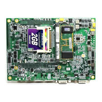
Advantech PCM-4380Z2-S0A2E User Manual (106 pages)
Brand:
Advantech
| Category:
Single board computers
| Size: 4.27 MB
Table of Contents
Table of Contents
7
Chapter 1 General Information
14
Introduction
14
Specifications
14
Standard 4" Biscuit SBC Functions
14
VGA/LVDS Interface
15
Ethernet Interface
15
Audio Function
15
Mechanical and Environmental
16
Board Layout and Dimensions
17
Chapter 2 Installation
20
Jumpers
20
Jumper Location
20
Jumper Settings
20
At/Atx Power Select (J1)
20
LCD Power (J2)
20
PCI-VIO Setting (J4)
20
CMOS Clear (S2)
21
COM2 Setting (J3)
21
Table 2.4 COM2 Setting (J3)
21
Connectors
22
Locating Connectors
23
Setting Jumpers
24
Installing SO-DIMM
25
IDE, CDROM Hard Drive Connector (CN27)
26
Connecting the Hard Drive
26
Solid State Disk
26
Compactflash (CN11)
26
Parallel Port Connector (CN30)
27
Keyboard and PS/2 Mouse Connector (CN19)
27
Power & HDD LED Connector(CN13)
27
Power Reset Button (S1)
27
Power Connectors (CN1)
28
Main Power Connector, +3.3V, +5 V, +12 V (CN1)
28
System FAN (CN5)
28
Audio Interfaces (CN31)
28
Audio Connector (CN31)
28
COM Port Connector (CN21,CN30)
28
COM2 RS-232/422/485 Setting (J3)
28
J3: COM2 RS-232/422/485 Select
28
VGA/LCD/LVDS Interface Connections
29
CRT Display Connector (CN16)
29
LVDS LCD Panel Connector (CN14)
29
Ethernet Configuration
29
100Base-T/1000Base-T Connector (CN8, CN9)
29
Network Boot (Depends on Ethernet Controller Gigabit Ethernet Only)
29
Watchdog Timer Configuration
29
USB Connectors (CN31,CN18)
30
GPIO (General Purpose Input Output) (CN7)
30
Chapter 3 Chipset Software Installation Utility
32
Before You Begin
32
Introduction
33
Installing the CSI Utility
33
Chapter 4 Award BIOS Setup
38
Introduction
38
CMOS RAM Auto-Backup and Restore
38
Entering Setup
39
Standard CMOS Setup
40
Advanced BIOS Features
41
L1 & L2 Cache
41
Virus Warning
41
Boot up Numlock Status
42
First/Second/Third/Other Boot Device
42
Gate A20 Option
42
Quick Power on Self Test
42
Typematic Delay (Msec)
42
Typematic Rate (Chars/Sec)
42
Typematic Rate Setting
42
APIC Mode
43
MPS Version Control for os
43
Security Option
43
Integrated Peripherals
43
IDE Master/Slave PIO/UDMA Mode
43
AC97 Audio
44
Init Display First
44
On-Chip Secondary PCI IDE
44
USB Controller
44
USB Keyboard/Mouse Support
44
ECP Mode Use DMA
45
EPP Mode Select
45
IDE HDD Block Mode
45
Onboard Parallel Port
45
Onboard Serial Port
45
Parallel Port Mode
45
Power Management Setup
46
ACPI Function
46
Power-Supply Type
46
HDD Power down
47
Modem Use IRQ
47
Power Management
47
Soft-Off by PWR-BTTN
47
Video off in Suspend
47
Fdd, Com, Lpt Port
48
Pci Pirq [A-D]
48
Poweron by Alarm
48
Poweron by LAN(Gigalan Option)
48
Poweron by Ring
48
Primary IDE 0 (1) and Secondary IDE 0 (1)
48
Pnp/Pci Configurations
49
PCI/VGA Palette Snoop
49
Pnp os Installed
49
Reset Configuration Data
49
Resources Controlled by
49
Password Setting
50
Save & Exit Setup
50
Exit Without Saving
50
Chapter 5 PCI SVGA/LCD Setup
52
Introduction
52
CMOS Setting for Panel Type
52
Display Type
52
Dual Independent Display
52
Connections to Two Standard Lcds
55
Connections to Lcd/Flat Panel (CN1)
55
LG LM 150X06 (1024X768 LVDS LCD)
55
AU M170EG01 (1024X768 LVDS LCD @ 36Bit)
56
Connections to au M170EG01 (CN1)
56
Installation of the SVGA Driver
57
Installation of Windows 2000
57
Further Information
60
Chapter 6 Audio Setup
62
Introduction
62
Driver Installation
62
Before You Begin
62
Windows 98 Drivers
63
Chapter 7 Ethernet Interface
68
Introduction
68
Installation of Ethernet Driver
68
Installation for Windows 2000
68
Further Information
74
Chapter 8 Installing MIO Modules
76
MIO Introduction
76
M2M Concept
76
Easy to Have Wireless Technology with Your Embedded Motherboard
76
The Best Board Combination for a System
76
Optional Modules
77
MIO-2310 Wireless Module
77
MIO-2320 GSM/GPRS Module
77
MIO Drawings
78
Appendix A Pin Assignments
80
Power Connector (CN1)
80
Battery Connector (CN4)
80
System FAN (CN5)
81
Power Switch (CN6)
81
Gpio (Cn7)
82
A.5 Gpio (Cn7)
82
Lan1(Rj45) (Cn8)
83
A.6 Lan1(Rj45) (Cn8)
83
A.7 Lan2(Rj45) (Cn9)
84
Lan2(Rj45) (Cn9)
84
Compact II Without Ejector (CN11)
85
HD & Power LED (CN13)
86
LVDS Connector (CN14)
87
Inverter Power (CN15)
88
A.12 Usb0/1 (Cn18)
89
Usb0/1 (Cn18)
89
Com1 (Cn21)
90
Keyboard/Mouse (CN19)
90
A.15 Isa_-5V (Cn24)
91
Isa_-5V (Cn24)
91
Rs-422/485 (Cn26)
92
A.17 Ide0 (Cn27)
93
Ide0 (Cn27)
93
Mio-Usb (Cn28)
94
Com2/3/4 & Lpt (Cn30)
95
USB2/3 & AC97 (Audio I/F) (CN31)
97
Appendix B Mechanical Drawings
100
Mechanical Drawings
100
Figure B.2 PCM-4380 Mechanical Drawing (Solder Side)
101
Appendix C DC Input Timing (Reference as ATX 2.2)
104
DC Input Timing
104
C.1 DC Input Timing
104
Appendix D Cables
106
Cables Table
106
Advertisement
Advertisement
Related Products
Advantech PCM-4380F-M0A2E
Advantech PCM-4380F-S0A2E
Advantech PCM-4380F-S4A2E
Advantech PCM-4380Z2-S4A2E
Advantech PCM-4822
Advantech PCM-5862EL
Advantech PCM-9371F-R0A1
Advantech PCM-9363D-S8A1E
Advantech PCM-9363N-S6A1E
Advantech PCM-9376F-M0A1E
Advantech Categories
Motherboard
Computer Hardware
Desktop
Touch Panel
Network Router
More Advantech Manuals
Login
Sign In
OR
Sign in with Facebook
Sign in with Google
Upload manual
Upload from disk
Upload from URL