Sign In
Upload
Manuals
Brands
Advantech Manuals
Single board computers
PCM-9363N-S6A1E
Advantech PCM-9363N-S6A1E Board Computer Manuals
Manuals and User Guides for Advantech PCM-9363N-S6A1E Board Computer. We have
1
Advantech PCM-9363N-S6A1E Board Computer manual available for free PDF download: User Manual
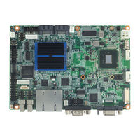
Advantech PCM-9363N-S6A1E User Manual (97 pages)
3.5" Biscuit with Intel Atom N455/D525, DDR3, 24-bit LVDS, CRT or HDMI, 2 Giga LAN, Mini PCIe, 3 COM
Brand:
Advantech
| Category:
Single board computers
| Size: 2 MB
Table of Contents
Ordering Information
4
Table of Contents
7
Chapter 1 General Introduction
11
Introduction
12
Product Feature
12
Specifications
13
Functional Specification
13
Mechanical Specifications
14
Electrical Specifications
15
Environmental Specifications
15
Operating Humidity
15
Operating Temperature
15
Storage Humidity
15
Storage Temperature
15
Chapter 2 H/W Installation
17
Jumpers
18
Jumper Description
18
Jumper List
18
Table 2.1: Jumper List
18
Jumper Settings
19
Table 2.2: J2: COM2 Setting
19
Table 2.3: J3: at / ATX Power SEL
19
Table 2.4: J4: Clear CMOS
19
Table 2.5: J5: PAN VOL SEL
20
Connectors
21
Connector List
21
Table 2.6: Connector List
21
Connector Settings
22
Mechanical
25
Jumper and Connector Locations
25
Figure 2.1 Jumper and Connector Layout (Component Side)
25
Figure 2.2 Jumper and Connector Layout (Solder Side)
25
Board Dimensions
26
Figure 2.3 Board Dimension Layout (Component Side)
26
Figure 2.4 Board Dimension Layout (Solder Side)
26
Figure 2.5 Board Dimension Layout (Coastline)
27
Figure 2.6 PCM-9363 HDMI Mechanical Drawing (Top View)
27
Chapter 3 BIOS Settings
29
Introduction
30
Entering Setup
30
Figure 3.1 Setup Program Initial Screen
30
Main Setup
31
Figure 3.2 Main Setup Screen
31
Advanced BIOS Features Setup
32
Figure 3.3 Advanced BIOS Features Setup Screen
32
Figure 3.4 CPU Configuration Setting
33
Figure 3.5 IDE Configuration
34
Figure 3.6 Super I/O Configuration
35
Figure 3.7 Hardware Health Configuration
36
Figure 3.8 ACPI Settings
37
Figure 3.9 General ACPI Configuration
37
Figure 3.10Advanced ACPI Configuration
38
Figure 3.11Chipset ACPI Configuration
38
Figure 3.12AHCI Configuration
39
Figure 3.13APM Configuration
40
Figure 3.14Event Log Configuration
41
Figure 3.15MPS Configuration
41
Figure 3.16Smbios Configuration
42
Figure 3.17USB Configuration
42
Figure 3.18USB Mass Storage Device Configuration
43
Advanced Pci/Pnp Settings
44
Figure 3.19PCI/PNP Setup (Top)
44
Boot Settings
45
Figure 3.20Boot Setup Utility
45
Figure 3.21Boot Setting Configuration
45
Security Setup
46
Figure 3.22Password Configuration
46
Advanced Chipset Settings
47
Figure 3.23Advanced Chipset Settings
47
Figure 3.24North Bridge Configuration
47
Figure 3.25Video Function Configuration
48
Figure 3.26South Bridge Configuration
49
Exit Option
50
Figure 3.27Exit Option
50
Chapter 4 S/W Introduction & Installation
53
S/W Introduction
54
Driver Installation
54
Windows XP Professional
54
Other os
54
Value-Added Software Services
54
SUSI Introduction
54
Software Apis
55
SUSI Utilities
56
SUSI Installation
57
SUSI Sample Programs
58
Appendix Apin Assignments
65
PIN Assignments
66
A.1 PIN Assignments
66
Table A.1: CN1: Audio
66
Table A.2: CN2: SATA
66
Table A.3: CN3: SATA
67
Table A.4: CN4: GPIO
67
Table A.5: CN5: HDD & PWR LED
68
Table A.6: CN6: 12 V Power Input
68
Table A.7: CN8: COM3
69
Table A.8: CN10: PS2
69
Table A.10:CN12: COM2
70
Table A.9: CN11: Smbus
70
Table A.11:CN13: Inverter Power Output
71
Table A.12:CN14: Internal USB
71
Table A.13:CN15: Internal USB
72
Table A.14:CN16: 18 or 24 Bits LVDS Panel
72
Table A.15:CN17: Single LAN (Optional)
73
Table A.16:CN18: LAN1
74
Table A.17:CN19: LAN2
74
Table A.18:CN20: Power Switch (Low Active)
74
Table A.19:CN21: LPT
75
Table A.20:CN22: HDMI (Optional)
76
Table A.21:CN23: Reset
77
Table A.22:CN24: External USB
77
Table A.23:CN25: External USB
78
Table A.24:CN26: COM1
78
Table A.25:CN27: VGA
79
Table A.26:CN28: Mini PCIE Lock
80
Table A.27:CN29: Mini PCIE Slot
80
Table A.28:CN30: DDR3 SODIMM
82
Table A.29:CN31: BIOS Socket
83
Table A.30:CN32: CF
84
Table A.31:CN36: SATA Power
85
Wdt & Gpio
87
Watchdog Timer Sample Code
88
GPIO Sample Code
89
Appendix B WDT & GPIO
95
Appendix C System Assignments
95
System I/O Ports
96
Table C.1: System I/O Ports
96
1St MB Memory Map
96
DMA Channel Assignments
97
Table C.3: DMA Channel Assignments
97
Interrupt Assignments
97
Table C.4: Interrupt Assignments
97
Advertisement
Advertisement
Related Products
Advantech PCM-9363
Advantech PCM-9363D-S8A1E
Advantech PCM-9371
Advantech PCM-9371F-J0A1
Advantech PCM-9371F-M0A1
Advantech PCM-9371F-R0A1
Advantech PCM-9376F-M0A1E
Advantech PCM-9375
Advantech PCM-9375E-J0A1E
Advantech PCM-9375F-J0A1E
Advantech Categories
Motherboard
Computer Hardware
Desktop
Touch Panel
Network Router
More Advantech Manuals
Login
Sign In
OR
Sign in with Facebook
Sign in with Google
Upload manual
Upload from disk
Upload from URL