Sign In
Upload
Manuals
Brands
ADTRAN Manuals
Power Supply
TOTAL ACCESS MX2800
ADTRAN TOTAL ACCESS MX2800 Manuals
Manuals and User Guides for ADTRAN TOTAL ACCESS MX2800. We have
2
ADTRAN TOTAL ACCESS MX2800 manuals available for free PDF download: User Manual, Manual
ADTRAN TOTAL ACCESS MX2800 User Manual (142 pages)
M13 Multiplexer
Brand:
ADTRAN
| Category:
Multiplexer
| Size: 5.17 MB
Table of Contents
Important Safety Instructions
6
Warranty and Customer Service
6
Table of Contents
9
List of Figures
13
Chapter 1. Introduction
17
Product Overview
17
Controller Card 1:1 Redundancy
18
T3 Overview
19
Snmp
19
Telnet
20
Available Options
20
Breakout Panel
20
Battery Backup
20
Chapter 2. Installation and Operation
21
Unpack, Inspect, Power up
21
Receiving Inspection
21
ADTRAN Shipments Include
21
Power up
22
Figure 2-1. DC Power Connector
23
Table 2-1. DC Connector Symbol Definitions
23
Rackmount Installation
24
Connecting the Breakout Panel
25
Rear Panel
26
Figure 2-2. the Breakout Panel
26
Figure 2-3. MX2800 Rear View
27
LAN Port
27
DSX-3 Interfaces
28
Modem Port
28
Noncritical and Critical Alarm Connectors
28
DSX-1/E1 Interfaces
29
Power Connection
29
Front Panel
29
Figure 2-4. MX2800 Front Panel
29
Craft Port
30
Establishing Terminal Connection
30
Navigating Within the Menus
31
Figure 2-5. Terminal Main Menu
31
ACO Buttons
32
LED Descriptions
33
Power Supply A/B
33
Status Leds
33
Table 2-2. LED Conditions for Active Cards
33
T1/E1 Status Leds
35
Table 2-3. LED Conditions for Standby Cards
35
Table 2-4. T1/E1 LED Conditions
36
Chapter 3. Configuration
37
Figure 3-1. Configuration Main Menu
37
Figure 3-2. Configuration Menu Tree
38
Network Interface
39
DS3 Configuration
39
Figure 3-3. Network Configuration Menu
39
Protection Configuration
41
Miscellaneous
42
DS2 Configuration
42
T1/E1 Interface
42
Figure 3-4. T1/E1 Interface Menu
42
T1/E1State
43
Set Multiple
43
Figure 3-5. T1/E1 State Menu
43
Figure 3-6. Set Multiple Menu
44
Figure 3-7. T1/E1 Line Coding Menu
44
T1/E1 Line Coding
44
Figure 3-8. T1/E1 Line Length Menu
45
T1/E1 Line Length
45
T1/E1 Loopback Detection
45
Figure 3-9. Loopback Detection Menu
46
T1/E1 Circuit Protection
46
Figure 3-10. Circuit Protection Menu
47
Figure 3-11. Line Identification Menu
47
T1/E1 Line Identification
47
XCV Threshold
48
System Management
48
Figure 3-12. System Management Configuration Menu
48
Management Options
49
Local IP Address
49
Gateway IP Address
49
Subnet Mask
49
Management Port
49
Dialup Options
49
Figure 3-13. Dialup Options Menu
49
Alarm Relays
52
Alarm Relay Configuration
52
Figure 3-14. Alarm Relay Configuration Menu
52
SNMP Management Options
55
Trap IP Addresses
55
Trap Generation
55
Figure 3-15. Trap Generation Menu
55
Read Community Name
60
Write Community Name
60
Trap Community Name
60
System Security
60
Password
60
Terminal Timeout
60
IP Security
61
IP Hosts
61
Date & Time
61
Miscellaneous
61
Equipment Identification
61
Figure 3-16. Equipment Identification Menu
61
Syslog Setup
62
Save on Logout
63
Table 3-1. Syslog Severity Levels
63
Utilities
64
Figure 3-17. System Utilities Menu
64
Updating Software
65
Via XMODEM
65
From a TFTP Server
65
Resetting the System
65
Save Configuration
66
Chapter 4. Status
67
DS3 State
67
Rx Framing
67
Figure 4-1. Status Menu
67
State
68
Alarm
68
Remote
69
Power Supply State
70
System State
71
Alarm
71
Card A/Card B
72
Protection
72
Card Comm
73
DS2 State
73
T1/E1 State
74
Acknowledge Alarms (ACO)
74
Chapter 5. Statistics
75
Viewing Statistical Information
75
Figure 5-1. Main Local Statistics Menu Screen
75
DS3 Statistics
76
24 Hour Alarm History
76
Figure 5-2. DS3 Statistics Menu
76
Figure 5-3. DS3 Current Alarm Count Screen
77
Performance Parameters
78
Figure 5-4. DS3 24-Hour Alarm History Screen
78
Figure 5-5. DS3 Performance Parameters (Current 15 Minutes)
79
Figure 5-6. DS3 Performance Parameters (24 Hour History)
80
DS2 Statistics
81
24 Hour Alarm History
81
Figure 5-7. DS3 Performance Parameters (Totals)
81
Performance Parameters
82
Figure 5-8. DS2 Statistics (Current 15 Minutes)
82
Figure 5-9. DS2 RAI 24-Hour Alarm History
82
Figure 5-10. DS2 Performance Parameters (Current 15 Minutes)
83
Figure 5-11. DS2 PBERR 24-Hour Alarm History
83
Figure 5-12. T1/E1 Statistics Menu
84
T1/E1 Statistics
84
Chapter 6. Diagnostics
85
Figure 6-1. Diagnostics Main Menu
85
T1/E1 Loopbacks
86
Tributary
86
Figure 6-2. T1/E1 Diagnostics Menu
86
Analog Network
87
Digital Line/Net
87
Figure 6-3. Tributary Loopback Test
87
Figure 6-4. Analog Network Loopback
87
Codec Line/Net
88
Remote Loopback
88
Figure 6-5. Digital Line/Network Loopback
88
Figure 6-6. Codec Loopback
88
CSU Loopback
89
CSU Loopback W/Bert
89
Line BERT
90
Figure 6-7. Diagnostics Menu with BERT Selected
90
DS3 Loopbacks
91
Line Loopback
91
Figure 6-8. DS3 Diagnostics Menu
91
Digital Diagnostics
92
Metallic Diagnostics
92
Figure 6-9. Line Loopback Test
92
Figure 6-10. Digital Diagnostics Loopback
92
Remote Loopback
93
Remote All T1/E1
93
DS2 Loopbacks
93
Figure 6-11. Metallic Diagnostics Loopback Test
93
DS2 Network
94
Figure 6-12. DS2 Diagnostics Menu
94
Figure 6-13. DS2 Network Loopback Test
94
Chapter 7. Circuit and Network Redundancy
95
Non-Redundant Mode
96
Figure 7-1. Non-Redundant Mode
96
Circuit Failure Recovery Mode
97
Figure 7-2. Circuit Failure Recovery Mode
97
Table 7-1. Configuration Requirements for Circuit Recovery
98
Circuit and Network Failure Recovery Mode
99
Figure 7-3. Circuit and Network Failure Recovery Mode
99
Chapter 8. Power Loss Recovery
102
Non-Redundant Power Mode
102
Figure 8-1. Non-Redundant Power Mode
102
Power Supply Recovery Mode
103
Figure 8-2. Power Supply Failure Recovery Mode
103
Power Supply and Source Recovery Mode
104
Figure 8-3. Power Supply and Source Failure Recovery Mode
104
Battery Backup Mode
105
Figure 8-4. Battery Backup System
105
Appendix A. Pinouts
107
Table A-1. Craft Port Pin Assignments
107
Table A-2. LAN Port Pin Assignments
108
Table A-3. Modem Port Pin Assignments
108
Table A-4. Amp Pin Assignments
109
Appendix B. Specifications Summary
111
Appendix C. Acronyms/Abbreviations
115
Appendix D. Glossary
119
Index
131
Advertisement
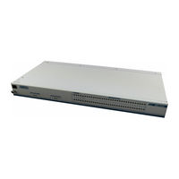
ADTRAN TOTAL ACCESS MX2800 Manual (1 page)
ADTRAN Network Device
Brand:
ADTRAN
| Category:
Power Supply
| Size: 0.47 MB
Advertisement
Related Products
ADTRAN MX2820
ADTRAN MX2800 M13
ADTRAN MX2800 STS-1
ADTRAN MX410
ADTRAN MX412
ADTRAN MX3216
ADTRAN Mitel IP
ADTRAN SMART/RG MC60
ADTRAN Modem-16 Module
ADTRAN Total Access 600R Total Access 604
ADTRAN Categories
Network Hardware
Network Router
Switch
Control Unit
Gateway
More ADTRAN Manuals
Login
Sign In
OR
Sign in with Facebook
Sign in with Google
Upload manual
Upload from disk
Upload from URL