Sign In
Upload
Manuals
Brands
ABB Manuals
Automobile Accessories
Terra HP Generation 3 UL
ABB Terra HP Generation 3 UL Manuals
Manuals and User Guides for ABB Terra HP Generation 3 UL. We have
2
ABB Terra HP Generation 3 UL manuals available for free PDF download: Installation Manual, User Manual
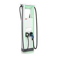
ABB Terra HP Generation 3 UL Installation Manual (100 pages)
UL 175 kW Static DC system
Brand:
ABB
| Category:
Battery Charger
| Size: 4.6 MB
Table of Contents
Table of Contents
3
About this Document
8
Function of this Document
8
Target Group
8
Revision History
8
Language
8
Illustrations
8
Units of Measurement
8
Typographical Conventions
8
How to Use this Document
8
General Symbols and Signal Words
9
Special Symbols for Warnings and Dangers
10
Related Documents
10
Manufacturer and Contact Data
11
Abbreviations
11
Terminology
12
Orientation Agreements
13
Safety
14
Liability
14
General Safety Instructions
14
Required Qualifications for the Installation Person
14
Personal Protective Equipment
15
Safety Instructions During Transport
15
Safety Instructions During Installation
15
Safety Instructions for Earthing
16
Signs on the EVSE
16
Discard the EVSE or Parts of the EVSE
17
Cyber Security
17
Description
19
Intended Use
19
Type Plate
19
General Description of the EVSE
20
Working Principle
20
Overview and Functions
21
Power Cabinet, Outside
21
Power Cabinet, Inside
22
DC Output Busbar in a Static DC System
23
Charge Post CP500 Generation 3, Outside
23
Charge Post CP500 Generation 3, Inside
24
Overview of the Cable Glands of the Charge Post
25
Pre-Installation
26
Pre-Installation Procedure (Site Planning)
26
Prepare the Site
26
Make Sure that the Floor Space for the EVSE and the Airflow Around the EVSE Is Correct
27
Prepare the Foundation
27
Prepare the Foundation - General Procedure
27
Prepare a Prefab Concrete Foundation for the Power Cabinet
27
Prepare a Metal Foundation for the Power Cabinet
28
Prepare a Custom Foundation for the Power Cabinet
29
Prepare a Prefab Concrete Foundation for the Charge Post
30
Prepare a Metal Foundation
31
Prepare a Custom Foundation for the Charge Post
31
Inspection and Transport
33
Transport the EVSE to the Site
33
Inspect the EVSE on Delivery
33
Do a Check on the Transport Sensors
33
Unpack the EVSE
33
Remove the Cabinet from the Pallet
34
Transport the EVSE on the Site
34
General Transport Procedure
34
Tilt the Charge Post to the Vertical Position
35
Move the Cabinet with a Forklift Truck
36
Hoist the Cabinet
36
Installation
38
General Installation Procedure
38
Mechanical Installation of the Power Cabinet
38
Install the Power Cabinet - General Procedure
38
Install the Cabinet on the Foundation
39
Open the Cable Inlets
39
Guide the Cables to the Cabinet
40
Close the Cable Inlets
40
Install the Front Cover Plate (Concrete Foundation)
40
Install the Cover Plates (Metal Foundation)
41
Mechanical Installation of the Charge Post
41
Install the Charge Post - General Procedure
41
Remove the Cable Gland Plates
42
Install the Charge Post on the Foundation
43
Install the Cable Gland Plates
43
Electrical Installation of the Power Cabinet
44
General Procedure
44
Connect the PE Cables to the Power Cabinet
44
Connect the AC Input Cables
45
Connect the DC Power Cables
46
Connect the AC Auxiliary Power Cable in the Primary Power Cabinet
47
Connect the Interlock and DC Guard Cables to the Power Cabinet
48
Connect the Optical CAN Cable between the Power Cabinet and the Charge Post
49
Electrical Installation of the Charge Post
50
General Procedure
50
Connect the PE Wires
50
Connect the DC Power Input Cables
51
Connect the AC Auxiliary Power Cable
52
Connect the Interlock and DC Guard Cable
53
Connect the Optical CAN Cable
54
Connect the Ethernet Cable
55
Prepare for Commissioning
57
Access to Parts
58
Open the Door of the Power Cabinet
58
Remove the Plinth Covers of the Power Cabinet
58
Remove the DC Busbar Cover
59
Remove the AC Covers
59
Close the Door of the Power Cabinet
60
Open the Door of the Charge Post
61
Remove the Plinth Covers of the Charge Post
61
Remove the Protection Plate of the Charge Post
62
Close the Door of the Charge Post
62
Generic Procedures
64
Install a Cable Lug on a Wire
64
Install a Ferrule on a Wire
64
Install Insulating Heatshrink Tubing on a Wire
65
Connect a Wire that Has a Cable Lug
66
Connect a Wire that Has a Ferrule
66
Technical Data
67
EVSE Type
67
Parts Included in the Delivery
67
Required Tools for Installation
68
Required Parts for Installation
68
General Specifications
69
Electrical Installation Specifications (North America)
69
Electrical Installation Specifications (Canada)
70
DC Output Specifications
70
Current Peaks During the Start of a Charge Session (DC Output)
71
Logic Interfaces Specifications
71
Mass and Center of Gravity
72
Mass
72
Center of Gravity, Power Cabinet
72
Center of Gravity, Charge Post
73
Ambient Conditions
73
Noise Level
74
Torque Specifications
74
Dimensions
74
Power Cabinet
74
Charge Post
75
Height of User Operable Elements
76
Space Requirements
77
Power Cabinet
77
Charge Post
78
Charge Post: Exceptions for Bollards and Other Minor Fixed Obstacles
79
Distance Requirements between Power Cabinet and Charge Post
80
Foundation Specifications
80
Power Cabinet (Prefab Concrete)
80
Power Cabinet (Metal Frame)
84
Gland Plates for the Metal Foundation of the Power Cabinet
85
Power Cabinet (Custom)
86
Charge Post (Prefab Concrete)
87
Charge Post (Metal Frame)
90
Gland Plates for the Metal Foundation of the Charge Post
91
Charge Post (Custom)
92
Overview of the Cable Conduits
93
Cable Specifications
95
AC Input Cable for the Power Cabinet
95
DC Power Installation Cables
95
PE Cable
96
AC Auxiliary Power Cables
96
Interlock and DC Guard Cables
97
Optical CAN Cables between the Power Cabinet and the Charge Post
97
Ethernet Cable
97
Expected Wye Input
98
Electrical Connection Diagram
99
Advertisement
ABB Terra HP Generation 3 UL User Manual (52 pages)
Brand:
ABB
| Category:
Automobile Accessories
| Size: 1.82 MB
Table of Contents
Table of Contents
3
About this Document
6
Function of this Document
6
Target Group
6
Revision History
6
Language
6
Illustrations
6
Units of Measurement
6
Typographical Conventions
7
How to Use this Document
7
General Symbols and Signal Words
7
Special Symbols for Warnings and Dangers
8
Related Documents
9
Manufacturer and Contact Data
9
Abbreviations
9
Terminology
10
Orientation Agreements
11
Safety
12
Liability
12
General Safety Instructions
12
Responsibilities for the Owner
12
Personal Protective Equipment
13
Safety Instructions for Use
13
Safety Instructions During Cleaning or Maintenance
13
Safety Instructions for Earthing
14
Signs on the EVSE
14
Discard the EVSE or Parts of the EVSE
15
Cyber Security
15
Description
16
Intended Use
16
Type Plate
16
Overview
17
Power Cabinet, Outside
17
Power Cabinet, Inside
18
Charge Post CP500 Generation 3, Outside
19
Charge Post CP500 Generation 3, Inside
20
Authorization to Charge
20
Dynamic DC Operation Modes
21
Description of the Touchscreen
22
General Description of the Layout
22
General Description of the Buttons
22
Options
23
Payment Terminal
23
Operation
24
Prepare before Use
24
Charge Session
24
General Procedure
24
Start a Charge Session
24
Stop a Charge Session
25
Energize the EVSE
26
De-Energize the EVSE
27
Measure the AC Voltage
28
Measure the DC Voltage (Power Cabinet, Static DC System)
28
Measure the DC Voltage (Power Cabinet, Dynamic DC System)
29
Measure the DC Voltage (Charge Post)
29
Maintenance and Cleaning
30
Maintenance Schedule
30
Clean the Cabinet
31
Do a Check on the Power Cabinet
31
Do a Visual Check of the EVSE
31
Remove a Sticker
32
Apply a Sticker
32
Troubleshooting
34
Troubleshooting Procedure
34
Troubleshooting Table
34
Access to Parts
36
Open the Door of the Power Cabinet
36
Close the Door of the Power Cabinet
36
Open the Door of the Charge Post
37
Close the Door of the Charge Post
38
Technical Data
39
EVSE Type
39
General Specifications
39
Cleaning Specifications
40
Electrical Installation Specifications (North America)
40
Electrical Installation Specifications (Canada)
40
DC Output Specifications
41
Expected Wye Input
42
Logic Interfaces Specifications
42
Ambient Conditions
43
Noise Level
43
Maintenance Schedule for the Service Engineer
44
Dimensions
44
Power Cabinet
44
Charge Post
45
Height of User Operable Elements
46
Space Requirements
47
Power Cabinet
47
Charge Post
48
Charge Post: Exceptions for Bollards and Other Minor Fixed Obstacles
49
Distance Requirements between Power Cabinet and Charge Post
50
Advertisement
Related Products
ABB COMMANDER 300
ABB 3AES-PVS-175-MVCS-30-DW01
ABB 3AES-PVS-175-MVCS-30-DW02
ABB 3AXD50000018852
ABB 3AXD50000024175
ABB 3AXD50000024176
ABB 30-050-03
ABB 3KXA494400L006
ABB 30-050-01
ABB 3AXD50000018602
ABB Categories
Industrial Equipment
Controller
Measuring Instruments
Battery Charger
DC Drives
More ABB Manuals
Login
Sign In
OR
Sign in with Facebook
Sign in with Google
Upload manual
Upload from disk
Upload from URL