Elo TouchSystems 1529L User Manual
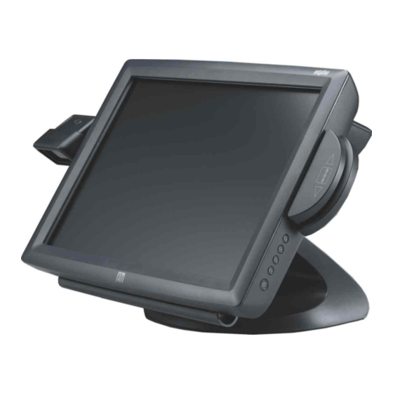
15” lcd touchmonitor
optional magnetic stripe reader,
customer display, barcode scanner
Hide thumbs
Also See for 1529L:
- User manual (70 pages) ,
- Product dimensions (4 pages) ,
- Specifications (2 pages)
Table of Contents
Advertisement
Quick Links
Download this manual
See also:
User Manual
Advertisement
Table of Contents

Related Manuals for Elo TouchSystems 1529L


Summary of Contents for Elo TouchSystems 1529L
- Page 1 Touchmonitor User Guide 1529L 15” LCD Desktop Touchmonitor, 3000 series (Optional Magnetic Stripe Reader and Customer Display) ...
- Page 2 ELO Touch Solutions 15” LCD Touchmonitor Optional Magnetic Stripe Reader, Customer Display, Barcode Scanner User Guide Revision G ...
- Page 3 Copyright © 2014 ELO Touch Solutions. All Rights Reserved. No part of this publication may be reproduced, transmitted, transcribed, stored in a retrieval system, or translated into any language or computer language, in any form or by any means, including, but not limited to, electronic, magnetic, optical, chemical, manual, or otherwise without prior written permission of ELO Touch Solutions. Disclaimer The information in this document is subject to change without notice. ELO Touch Solutions and its Affiliates makes no representations or warranties with respect to the contents herein, and specifically disclaims any implied warranties of merchantability or fitness for a particular purpose. ELO Touch Solutions reserves the right to revise this publication ...
-
Page 4: Table Of Contents
OSD Control Options ........... 33 Appendix B Brightness ............33 Technical Specifications Contrast ............33 Sharpness ............33 Touchmonitor Specifications ......35 Phase .............. 33 15” LCD Touchmonitor (1529L)Dimension ........35 15” LCD Touchmonitor (1529L)Dimension ........36 Regulatory Information Warranty... -
Page 5: Introduction
(VFD) Customer Display, fingerprint reader, barcode scanner, credit card reader, and a 6 port USB (USB version only) Hub. The main display element is a 15.0 inch diagonal XGA resolution (1024 x 768) LCD display. The main display will consist of an LCD Display and touchscreen. Four types of touchscreens can be selected in the 1529L as options. They are AccuTouch, Intellitouch. The credit card reader reads all three stripes on a standard credit card or drivers license. The credit card is read by sliding the credit card, stripe side toward the display through the credit card reader forward or backward. There is a USB credit card reader only. The Hub provides 2 internal USB ports to be used by the credit card reader and the touchscreen. The hub also supplies two USB ports to the outside of the back of the 1529L for external use. The hub is only used by the USB version of the 1529L. The 1529L is powered by a universal AC power source or 12 VDC from external power source. ... -
Page 6: Detailed Lcd Display Performance Requirements
Detailed LCD Display Performance Requirements 15 inch TFT LCD Display Panel Display Format 1024 x 768 Display area 15” 304.1mm(H) x 228mm(V) Pixel Pitch 15” 0.297mm(H) x 0.297mm(V) Contrast Ratio 700:1 typical Brightness 350 cd/m (Typical) ; 270 cd/m (Minimum) AccuTouch 280 cd/m (Typical) ; 203 cd/m (Minimum) IntelliTouch 315 cd/m... -
Page 7: Credit Card Reader
Credit Card Reader There is a USB credit card reader only. The USB version is available in HID and Key‐ board emulation versions. The reader reads all three stripes on a standard credit card or drivers license. Reference Standards‐Conform to International Standards Organization, American National Standards applicable standards Institute, California Drivers License, American Association of Motor Vehicle Administrators Message Format ACCII Card Speed 3 to 50 IPS MTBF Electronics 125,000 hrs; Head 1,000,000 passes Two Port USB Hub The Hub provides 2 internal USB ports to be used by the credit card reader and the touchscreen. The hub also supplies two USB ports to the outside of the back of the 1529L for external use. The hub is only used by the USB version of the 1529L. The hub meets the following requirements: Specification Full compliance with USB specification 1.0, 1.1 and 2.0 and HID Class Definition Rev 1.0. Hub shall be self powered Hub shall provide 2 external and 4 internal downstream ports with individual port over current detection, protection and recovery. Supports both Open Host Controller Inter‐ face (OHCI) and Universal Host Controller Interface (UHCI). Supports Suspend and Resume operation. Bus fault detection and recovery. External Power Supply The 1529L shall be powered by a universal AC power source or 12 VDC from external power source. The power supply shall provide the following capability: AC power: Input voltage 90 to 264 vac Input frequency 47 to 63hz DC power: Input voltage 12 vdc Input line and load regulation +/‐2% ... -
Page 8: Installation And Setup
C H A P T E R INSTALLATION AND SETUP This chapter discusses how to install your LCD touchmonitor and how to install Elo TouchSystems driver software. Unpacking Your Touchmonitor Check that the following items are present and in good condition: Touchmonitor USB Cable Video cable Power cable US/Candian European power cable DVI cable ... -
Page 9: Product Overview
Product Overview Main Unit Note: Shown with optional Biometric & MSR. Rear View Note: Shown with optional Rear Facing Customer Display. ... -
Page 10: Side View
Side View Base Bottom View ... -
Page 11: Kensington Lock
TM Kensington Lock The Kensington TM lock is a security device that prevents theft. To find out more about this security device, do to http://www. kensington.com. ... -
Page 12: Remove The Cable Cover
ccUSB Interface Connection Your touchmonitor comes with only one touchscreen connector cables: USB cable. (For Windows 2000, Me and XP systems only.) To set up the display, please refer to the following figures and procedures: Remove the Cable Cover The cables are connected at the back of the monitor. cable cover To remove the cover, grasp the lip of the cover and pull towards you until it snaps off. ... - Page 13 AUTION Before connecting the cables to your touchmonitor and PC, be sure that the computer and touchmonitor are turned off. OTE Before connecting the cables to the touchmonitor, route all the cables through the hole in the second as shown in the picture above. ...
- Page 14 The following illustrations guide you step by step in connecting your touchmonitor using a USB cable connection. Power cord Connect one end of the power cord to the monitor and the other end to wall. Connect the power cable to the power port in the monitor. ...
- Page 15 Video cable Connect one end of the video cable to the rear side of computer and the other to the LCD. Tighten by turning the two thumb screws clockwise to ensure proper grounding. You can select DVI video cable or D‐SUB15 video cable. ...
- Page 16 Speaker cable Connect one end of the speaker cable to the speaker port in the computer and the other end to the port in the monitor. ...
- Page 17 USB cable Connect one end of the USB cable to the rear side of the computer and the other to the LCD monitor. The USB cable is for optional touch, MSR. Only one USB cable is needed because the device contains a self powered USB 1.1 Hub. Two self powered ports are available for running other USB devices. For touch only, no USB Hub is present. ...
-
Page 18: Replace The Cable Cover
Replace the Cable Cover Cable cover lip cables Then you have attached all the cables to the monitor, gently bring all the cables toward the standard so they fit under the cover lip. Snap the Cable cover in place over the connections. ... -
Page 19: Optimizing The Lcddisplay
Optimizing the LCD Display To ensure the LCD display works well with your computer, configure the display mode of your graphic card to make it less than or equal to 1024 x 768 resolution, and make sure the timing of the display mode is compatible with the LCD display. Refer to Appen‐ dix A for more information about resolution. Compatible video modes for your touchmonitor are listed in Appendix C. Installing the Peripheral Device Drivers Magnetic Stripe Reader No device are needed. Testing the USB MSR Keyboard Emulation 1 Plug in the device. 2 Open MS Word. 3 Slide the card through the MSR to view the data. Testing the USB‐HID Class MSR 1 On the CD, browse to Touch Monitor Peripherals\Magnetic Stripe Card Readers\Demo. 2 Open the Readme.txt and follow instructions to test the unit. ... -
Page 20: Installing The Driver Software
Installing the Driver Software ELO Touch Solutions provides driver software that allows your touchmonitor to work with your computer. Drivers are located on the enclosed CD‐ROM for the following operating systems: • Windows 7 • Windows Vista • Windows XP • Windows 2000 • Windows Me • Windows 98 • Windows 95 • Windows NT 4.0 • Windows 3.1 • MS‐DOS Additional drivers and driver information for other operating systems are available on the Elo TouchSystems web site at www.elotouch.com. The Elo touchmonitor is plug‐and‐play compliant. Information on the video capabilities of your touchmonitor is sent to your video display adapter when Windows starts. If Windows detects your touchmonitor, follow the instructions on the screen to install a generic plug‐and‐play monitor. Refer to the following appropriate section for driver installation instructions. Depending upon whether you connected the serial communication cable or the USB ... -
Page 21: Installing The Serial Touch Driver
Installing the Serial Touch Driver Installing the Serial Touch Driver for Windows 7, Windows Vista, indows XP, Windows 2000, ME, 95/98 and NT4.0. NOTE: For Windows 2000 and NT4.0 you must have administrator access rights to install the driver. Make sure the serial connector (RS232) is plugged into the monitor and an open com port on the PC. 1 Insert the Elo CD‐ROM in your computer's CD‐ROM drive. 2 If the AutoStart feature for your CD‐ROM drive is active, the system automatically detects the CD and starts the setup program. 3 Follow the directions on the screen to complete the driver setup for your version of Windows. 4 If the AutoStart feature is not active: 5 Click Start > Run. 6 Click the Browse button to locate the EloCd.exe program on the CD‐ROM. 7 Click Open, then OK to run EloCd.exe. 8 Follow the directions on the screen to complete the driver setup for your version of Windows. ... -
Page 22: Chapter 3 Operation
C H A P T E R OPERATION About Touchmonitor Adjustments Your touchmonitor will not likely require adjustment. Variations in video output and application may require adjustments to your touchmonitor to optimize the quality of the display. For best performance, your touchmonitor should be operating in native resolution that is 1280 x 1024 at 80 k‐75 Hz. Use the Display control panel in Windows to choose 1280 x 1024 resolution. ... -
Page 23: 15" Lcd Function Key
15” LCD Function Key Controls Function 1 Power Switch Turns the display system power on or off. 2 Select Displays the OSD menus on the screen and used to select (“Clockwise” and “Counter‐clockwise” direction) the OSD control options on the screen. ... -
Page 24: Controls And Adjustment
Controls and Adjustment OSD Lock/Unlock You are able to lock and unlock the OSD feature. The monitor is shipped in the unlocked position. To lock the OSD: 1 Press the Menu button and button simultaneously for 2 seconds. A window will appear displaying “OSD Unlock”. -
Page 25: Osd Control Options
OSD Control Options Brightness • Background Luminance of the LCD panel is adjusted. Contrast • Adjusts the contrast or the values of color gain (RED, GREEN or BLUE). Sharpness • The sharpness can be adjustable. Phase • Adjusts the phase of the dot clock. Auto Adjust • Clock system auto adjustment (under 5 seconds). OSD Left/Right • The OSD screen is moved vertically right and left. OSD Up/Down • The OSD screen is moved vertically up and down. Clock • Adjusts the ratio of dividing frequency of the dot clock. Color Temperature • Sets R, G, B gain. Current Input • The frequency of the horizontal/vertical synchronizing signal under the input indicated. (This information is under Auto Adjust icon) OSD Position • Allows the OSD indication position to be selected. ... -
Page 26: Language
Language • Select the language used for the OSD menu from among English, France, Deutsch, Spanish and Japanese. Recall Defaults • All data copy from factory shipment data. OSD Timeout • Adjust time for OSD to disappear. Input Video Select • Select D‐SUB Analog, DVI Digital signal. Volume • To increase or decrease the sound level. Power‐Save (No Input) • The LCD panel background is cut when there is no signal input (AC line power consumption of 4w or less). Power LED Display & Power Saving General Power Saving Mode When the power switch are switch on, this LED lights in green. The LED indicates the different power status with altered LED colors when monitor operates in different modes (see following table). Power Mode Indicator Consumption On 41w max. Green Orange 1.7w max. Sleep NO Off 0.5w ... -
Page 27: Display Angle
Display Angle For viewing clarity, you can tilt the LCD forward up 67 to 90 degrees. CAUTION In order to protect the LCD, be sure to hold the base when adjusting the LCD, and take care not to touch the screen. ... -
Page 28: Controls And Adjustment
Controls and Adjustment OSD Lock/Unlock You are able to lock and unlock the OSD feature. The monitor is shipped in the unlocked position. To lock the OSD: 1 Press the Menu button and button simultaneously for 2 seconds. A window will appear displaying “OSD Unlock”. Continue to hold the buttons down for another 2 seconds and the window toggles to “OSD Lock”. Power Lock/Unlock You are able to lock/unlock the Power feature. The monitor is shipped in the unlockedposition.To lock the power: 1 Press the Menu button and the simultaneously for 2 seconds. A window for another 2 seconds and the window toggles to —Power Lock“. OSD Menu Functions To display the OSD Menu press the Menu button. 1 Press the button or ... -
Page 29: Osd Control Options
OSD Control Options Brightness • Background Luminance of the LCD panel is adjusted Contrast • Gain of R, G, and B signal is adjusted. Sharpness • The sharpness can be adjustable. Phase • The phase of the dot clock is adjusted. Auto Adjust • Automatically adjusts the systems dot clock(takes approximately 5 seconds). OSD Left/Right • The osd screen is moved horizontally left and right. OSD Up/Down • The OSD screen is moved vertically up and down. Clock • The ratio of dividing frequency of the dot clock is adjusted. Color Temperature • Sets the R, G, and B gains. Current Input • The frequency of the horizontal/vertical synchronizing signal under the input is indicated.(These ... -
Page 30: Language
Language • Select the language for the OSD menu from among English, France, Deutsch, Spanish and Japanese. Recall Defaults • Restore all original factory defaults. OSD Timeout • Adjust how long the OSD menu is displayed. Input Video Select • Select D‐SUB Analog, dvi Digital signal. Volume • To increase or decrease the sound level. ... -
Page 31: Troubleshooting
C H A P T E R TROUBLESHOOTING If you are experiencing trouble with your touchmonitor, refer to the following table. If the problem persists, please contact your local dealer or our service center. Solutions to Common Problems Problem Suggestion(s) The monitor does not respond 1. Check that the monitor’s Power Switch is on. when turning on the system. 2. Turn off the power and check the monitor’s DC power cord and signal cable for proper connection. Characters on the screen are dim R efer to the About Touchmonitor Adjustments section to adjust the brightness. ... -
Page 32: Appendix A Touchmonitor Safety
C H A P T E R A TOUCHMONITOR SAFETY This manual contains information that is important for the proper setup and maintenance of your touchmonitor. Before setting up and powering on your new touchmonitor, ... -
Page 33: Care And Handling Of Your Touchmonitor
Care and Handling of Your Touchmonitor The following tips will help keep your touchmonitor functioning at the optimal level. • To avoid risk of electric shock, do not disassemble the brick power supply or display unit cabinet. The unit is not user serviceable. Remember to unplug the display unit from the power outlet before cleaning. • Do not use alcohol (methyl, ethyl or isopropyl) or any strong dissolvent. Do not use thinner or benzene, abrasive cleaners or compressed air. • To clean the display unit cabinet, use a cloth lightly dampened with a mild detergent. • Avoid getting liquids inside your touchmonitor. If liquid does get inside, have a qualified service technician check it before you power it on again. • Do not wipe the screen with a cloth or sponge that could scratch the surface. • To clean the touchscreen, use window or glass cleaner. Put the cleaner on a clean cloth and wipe the touchscreen. Never apply the cleaner directly to the touchscreen. ... -
Page 34: Technical Specifications
C H A P T E R B TECHNICAL SPECIFICATIONS Touchmonitor Specifications Model 1529L LCD Display 15.0” TFT Active Matrix Panel Display Size 304.1(H) x 228(V) mm Pixel Pitch 0.297(H) x 0.297(V) mm Display Mode VGA 640 x 350 (70 Hz) VGA 720 x 400 (70 Hz) VGA 640 x 480 (60 / 72 / 75 Hz) SVGA 800 x 600 (56 / 60 / 72 / 75Hz) XGA 1024 x 768 (60 / 70 / 75Hz) Native XGA 1024 x 768 Contrast Ratio 700 : 1 (typical) 2 2 Brightness 350 cd/m , AT 280 cd/m , IT 315 cd/m... - Page 35 。 。 。 。 Operating Conditions Temp C ~ 40 C (41 F ~ 95 F) Humidity 20% ~ 80% (No Condensation) Altitude To 10,000 Feet Dimensions (HxWxD) 354 x 301 x 285mm Weight (Net) 20.1lbs., monitor weight 16.2 lbs. Certifications UL, C‐UL, FCC‐B, CE, Semko, VCCI, MPRII, C‐TICK, Argentina S‐Mark ...
-
Page 36: 15" Lcd Touchmonitor (1529L)Dimension
15” LCD Touchmonitor(1529L) Dimensions 15” LCD Touchmonitor(1529L) Dimensions ... - Page 37 REGULATORY INFORMATION I. Electrical Safety Information: A) Compliance is required with respect to the voltage, frequency, and current requirements indicated on the manufacturer’s label. Connection to a different power source than those specified herein will likely result in improper operation, damage to the equipment or pose a fire hazard if the limitations are not followed. B) There are no operator serviceable parts inside this equipment. There are hazardous voltages generated by this equipment which constitute a safety hazard. Service should be provided only by a qualified service technician. C) Contact a qualified electrician or the manufacturer if there are questions about the installation prior to connecting the equipment to mains power. II. Emissions and Immunity Information A) Notice to Users in the United States: This equipment has been tested and found to comply with the limits for a Class B digital device, pursuant to Part 15 of FCC Rules. These limits are designed to provide reasonable protection against harmful interference in a residential installation. This equipment generates, uses, and can radiate radio frequency energy, and if not installed and used in accordance with the instructions, may cause harmful interference to radio communications. B) Notice to Users in Canada: This equipment complies with the Class B limits for radio noise emissions from digital apparatus as established by the Radio Interference Regulations of Industrie Canada. ...
- Page 38 D) General Information to all Users: This equipment generates, uses and can radiate radio frequency energy. If not installed and used according to this manual the equipment may cause interference with radio and television communications. There is, however, no guarantee that interference will not occur in any particular installation due to site‐specific factors. 1) In order to meet emission and immunity requirements, the user must observe the following: a) Use only the provided I/O cables to connect this digital device with any computer. b) To ensure compliance, use only the provided manufacturer’s approved line cord. c) The user is cautioned that changes or modifications to the equipment not expressly approved by the party responsible for compliance ...
- Page 39 III. Agency Certifications The following certifications have been issued for this monitor: •Argentina S‐Mark •Australia C‐Tick •Canada CUL •Canada IC •Europe CE •Japan VCCI •Europe Semko •United States UL •FCC •Sweden MPR II Laser Notice CAUTION: Laser radiation when open. DO NOT STARE INTO BEAM. ...
-
Page 40: Warranty
WARRANTY Except as otherwise stated herein or in an order acknowledgment delivered to Buyer, Seller warrants to Buyer that the Product shall be free of defects in materials and workmanship. The warranty for the touchmonitors and components of the product is 3 (three) years. Seller makes no warranty regarding the model life of components. Seller’s suppliers may at any time and from time to time make changes in the components delivered as Products or components. Buyer shall notify Seller in writing promptly (and in no case later than thirty (30) days after discovery) of the failure of any Product to conform to the warranty set forth above; shall describe in commercially ... - Page 41 CONSEQUENTIAL, INDIRECT, O R I NCIDENTALDAMAGES. Buyer assumes the risk and agrees to indemnify Seller against and hold Seller harmless from all liability relating to (i) assessing the suitability for Buyer’s intended use of the Products and of any system design or drawing and (ii) determining the compliance of Buyer’s use of the Products with applicable laws, regulations, codes, and standards. Buyer retains and accepts full responsibility for all warranty and other claims relating to or arising from Buyer’s products, which include or incorporate Products or components manufactured or supplied by Seller. Buyer is solely responsible for any and all represen‐ tations and warranties regarding the Products made or authorized by Buyer. Buyer will indemnify Seller ...
- Page 42 Check out Elo’s Web site www.elotouch.com Get the latest... Product Information Specifications Upcoming events Press release Getting in Touch with Us To find out more about the extensive range of Elo touch solutions, visit our website at www.elotouch.com, or simply call the office nearest you: North America Tel 800-ELO-TOUCH Europe Asia-Pacific Latin America Elo Touch Solutions Tel + 1 408 597 8000 Tel +32 (0) 16 70 45 00 Tel +81 (45) 478 2161 Tel 786-923-0251 Fax +1 408 597 8050...
Need help?
Do you have a question about the 1529L and is the answer not in the manual?
Questions and answers