Table of Contents
Advertisement
Safety Precautions
Read and follow the content of the Safety Precautions carefully so that you will not cause
damages to yourself or the system.
1. Pay attention to the warnings and notes in this manual to avoid causing unexpected
damages.
2. If you want to wipe the system with a wet cloth, make sure the power cord is
disconnected. We strongly suggest not to wipe the system with chemical detergent or
sprayed detergent.
3. When moving the system, do not put the system on uneven, unsteady or slanting
surfaces.
4. Do not put water cups or beverages near the PC system to protect the system from
being damaged by liquids.
5. There are ventilating holes on the backboard of the computer case to dissipate heat
from the machine. You should pay attention to the position of the PC so that the
ventilating holes will not be blocked. Meanwhile, do not put your PC on something
not sturdy enough – like rug or bed mattress – to ensure smooth air flow for heat
dissipation.
6. Before plugging on power, make certain the electric voltage in your area complies
with that of the PC. If you are uncertain, consult your PC dealer or power company
first.
7. Do not place your PC on power cords. Do not leave the power lines in tangles which
may cause people to stumble.
8. It normally takes several power sockets to meet the need of a PC system. Make sure
the extension power line is capable of handling the total power load for all equipment.
In other words, the combined amperage of all electrical appliances on the same
1
Advertisement
Table of Contents

Related Manuals for AOpen EPC945-M8


Summary of Contents for AOpen EPC945-M8
-
Page 1: Safety Precautions
Safety Precautions Read and follow the content of the Safety Precautions carefully so that you will not cause damages to yourself or the system. 1. Pay attention to the warnings and notes in this manual to avoid causing unexpected damages. 2. - Page 2 extension line must not exceed the strength of electric currents or the fuse of the extension line. 9. When your PC system runs into problems, do not try to fix it unless you possess adequate technical know-how concerning hardware installation and system maintenance.
-
Page 3: Safety Instructions
Disposal Instruction For better protection of our earth, please don't throw this electronic device into municipal trash bin when discarding. To minimize pollution and ensure utmost protection of the global environment, please recycle the product. For more information about the collection and recycling of Waste Electrical and Electronic Equipment (WEEE) , you are invited to visit our homepage at www._____.com under “Green Products”. -
Page 4: Table Of Contents
Table of Contents Chapter 1 Getting Started....………………………………………………….5 System Overview …………………………………………………………………………5 Features …………………………………………………………………………………...5 Unpacking Your System ………….………………..……………………………………...6 The Front View ………………..…………………………………………………….……7 USB 2.0 Card Reader ……………………………………………………………………7 Input/Output Ports and Buttons on Front Panel ………………………………….…..….9 The Rear View ……………………………………………………………………….… 9 TV Outputs …………………………….………………………………………………..12 The Remote Control …………………..………………………………………………...13 Chapter 2 Install and Disassemble System…………………………………………..15 Install the CPU ……………………………………………………………………….…15... -
Page 5: Chapter 1 Getting Started
Chapter 1 Getting Started System Overview Thank you for purchasing XC REC 8, an entertainment PC (ePC). The system unit is designed to integrate the functions of the following appliances: DVD player Personal video recorder Audio CP player Internet Set-top box FM tuner AC3 decoder PC game console... -
Page 6: Unpacking Your System
The first smallest ViiV desktop ePC that supports four slots. The first smallest ViiV desktop ePC that supports the micro ATX form factor. The first smallest ViiV desktop ePC that supports Intel 8xx dual core 130W CPU which is designed to be cooled with four heat-pipes and an extra large 95 mm fan. The first smallest ViiV desktop ePC that supports multiple video outputs including VGA, YPbPr, S-Video, composite video, SCART (optional for Europe), and D4 (optional for Japan). -
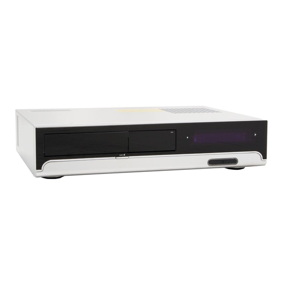
Page 7: The Front View
The Front View The power button of the unit is covered under a slim panel near the bottom of the front panel. When facing the front panel, you can locate an eject button which releases the cover of the optical disc drive and the card reader. You can locate other indicators such as HDD, Record, and remote control indicators. - Page 8 Supports flash memory card format including: Slot 1: SM/SMC interface MMC1/MMC2/MMC4.0 (1 bit) Secure Digital Card MS/MS(MG) MS PRO/MS PRO (MG) Memory Stick ROM MS Select with adapter MS Duo/MS Duo (MG) MS PRO Duo/ MS PRO Duo (MG) Mini-SD RS-MMC T-flash Slot 2:...
-
Page 9: Input/Output Ports And Buttons On Front Panel
Input/Output Ports and Buttons on Front Panel Input/Output ports and buttons on the front panel are concealed under a slim cover near the bottom edge of the front panel. A user can push both ends of the slim cover to open it. SPDIF Out Previous Next... - Page 10 Japan: S-video (connect to red head) D4 out (Japan only) Composite out (connect to yellow head) Mouse Y/Pb/Pr COAXIAL COM1 Add2 Card (DVI out) Keyboard 7.1-ch Audio Note: The system supports either Y/Pb/Pr video output or D4 output. If a user intends to use both connectors at the same time, the display screen will not work properly.
- Page 11 Note: If your system comes with a 275W power supply, you can find a red power rating selection switch on the rear panel. You should use that slide switch to select the appropriate power rating. In case your system comes with a 375W power supply, there is no need for manual selection.
-
Page 12: Tv Outputs
TV Outputs You can locate the TV output ports on the rear panel. The TV output ports are provided through the ADD2 video card. The video output port on the upper part of the ADD2 video card enables a user to connect the system to the S-Video, YPbPr, or the composite video input of a TV set. -
Page 13: The Remote Control
The Remote Control Remote Control/Function keys Remote Control Button Description Power Turns power ON/OFF STOP Stop the current action RECORD Records A/V unto DVD disc or PAUSE Frame-by-Frame pauses and pause recording Fast Rewind PLAY Plays the selected media Fast Forward. REPLAY Replay SKIP... - Page 14 RECORD TV recording GUIDE Guide information LIVE TV TV mode DVD MENU Display DVD menu Alphanumer Enter alphanumerical letters ic keys CLEAR Clear input ENTER Confirm input...
-
Page 15: Chapter 2 Install And Disassemble System
Chapter 2 Install and Disassemble system Install the CPU In order to install the CPU, you have to: Remove the top cover Remove the link bar Remove the CPU cooler Remove the Top Cover A user can disassemble the upper case by removing the two screws on the two sides of the rear panel. -
Page 16: Remove The Link Bar
Remove the Link Bar Three screws fasten the link bar to the chassis. Remove the three screws. Lift the link bar by pulling up its end near the rear chassis. -
Page 17: Remove The Cpu Cooler
Remove the CPU Cooler Your system may come with or without a CPU cooler depending on the various configurations marketed by your distributor. The CPU cooler is fixed to the motherboard with four screws. Removing the screws with a screw driver with magnetic tip will make the job a lot easier. -
Page 18: Install Cpu On Socket T
Install CPU On Socket T 1. Remove plastic cap and lift CPU socket lever. Plastic Cap Lever 2. Lift CPU socket plate and install CPU to CPU socket. Then press plate back to cover the CPU socket. Plate 3. Press down CPU socket lever to finish CPU installation. -
Page 19: Install Cpu To Socket 754
Install CPU to Socket 754 1. Lift CPU socket lever and gently install CPU to its socket. Lever 2. Press lever back to CPU socket to finish the installation. -
Page 20: Install Cpu To Socket 479
Install CPU to Socket 479 1. Remove plastic membrane from CPU socket and make sure the drop-shaped indicator on socket screw aim at open direction (the default is open). Plastic membrane Socket screw 2. Match socket Pin 1 and golden arrow, and gently install CPU to its socket. Then lock socket screw clockwise to finish CPU installation. -
Page 21: Install Cpu To Socket 939
Install CPU to Socket 939 1. Lift CPU socket lever and gently install CPU to its socket. 2. Press lever back to CPU socket to finish CPU installation. -
Page 22: Install Memory Modules
Install Memory Modules The memory module is built with a fool-proof notch. The notch makes sure that the memory module will not be installed incorrectly. The notch should match an extruding point of the memory socket. Press down the memory modules into the slots and lock them onto the slots with the clasps on two sides of the slots. - Page 23 To remove the optical disc drive from the cage, remove the power and flat cables connected to the optical device. Remove the screws using an appropriate screw driver. Slide the optical device toward the rear of the chassis. Once the optical device is moved clear of the front edge of the front panel, lift it up vertically.
-
Page 24: Install Optical Disc Drive
Install Optical Disc Drive When holding the optical disc drive with its front pointing toward the front panel of the system, locate two screw holes near the top of the optical disc drive. We will refer to this side as the left side of the optical device hereafter. Fasten the two screws which are designed specially for fixing the optical disc drive to the drive cage. - Page 25 Slide the optical disc drive toward the front panel with your left hand, while keeping the optical device drive door open with your right hand. You can use a finger to push the lower edge of the optical device drive door to open it. The two screws which have just been fixed to the optical drive have to slide into the slits on the side of the drive cage.
- Page 26 slightly, allowing yourself to make slight adjustment to the optical device. Note 1: While the optical device drive door is held open, press the Eject button on the front panel, and you will see a black tab which can be activated by the Eject button. The Eject button on the front panel is so designed that once a user press that button, the black tab will touch the real Eject button on the front of the optical drive and cause the optical drive to eject its disc tray.
-
Page 27: Disassemble Hard Disc Drive
Disassemble Hard Disc Drive Your system may come with or without hard disc drive. Therefore, you may want to learn the steps to disassemble the hard disc drive. To disassemble the hard disc drive, you have to disassemble the optical disc drive first. The drive cage is fastened to the chassis with two screws. -
Page 28: Lift The Drive Cage
Lift the Drive Cage. In case a hard disc drive is installed in the drive cage, you can remove the four screws which fasten the hard drive to the drive cage. Two 3.5-inch hard drives can be installed to the drive cage. Each hard drive is fastened to the drive cage with four screws. Install Hard Disc Drive Two 3.5-inch hard drives can be installed to the drive cage. - Page 29 Fasten the two screws to attach the drive cage to the chassis.
-
Page 30: Chapter 3 Turn On The Power
Chapter 3 Turn on the Power 1. Turn on the power. After all cables have been properly connected, you can turn on the power. 2. Set BIOS (Basic Input/Output System). Not long after turning on the power, you'll see the following screen. You can press the Delete button to get into the BIOS setup menu. - Page 31 After pressing Delete, you'll see the following BIOS setup: You can move the cursor by using direction keys on the keyboard. Move the cursor to the option item "Load Setup defaults" and press Enter...
- Page 32 Then, the following dialogue screen will pop up to confirm the default BIOS values. Please press "Y" to confirm, and then press Enter Finally, move the cursor to "Save & Exit Setup" and press Enter to save the parameters and exit BIOS setup.
- Page 33 At the same time, type "Y" in the dialogue box and press Enter to exit.
-
Page 34: Appendix
Appendix Install OS into Serial ATA Hard Disk It is equipped with the powerful chipset which supports Serial ATA interface. Please note that when loading the operating system onto a Serial ATA hard disk, there will be certain limitations due to the limitations of the chip. Please carefully follow the procedures below to install Windows 2000/XP/MCE. -
Page 35: Raid Driver Installation Guide
build RAID in Windows 2000 or Windows XP. To enable the RAID function, the user has to install a driver program from a floppy disk drive. Please connect the floppy drive to motherboard before installing the operating system. The user needs to install two Serial ATA hard drives to build the RAID system. -
Page 37: Introduction To Jumper Settings And Other Connectors
Introduction to Jumper Settings and Other Connectors JP14 Clear CMOS You can clear CMOS to restore system default setting. To clear the CMOS, follow the procedure below. 1. Turn off the system and unplug the AC power. 2. Remove ATX power cable from connector PWR2. 3. - Page 38 CPU and System Fan Connector Plug the CPU fan cable to the 3-pin CPUFAN1 connector. If you have chassis fan, you can also plug it into SYSFAN2. CPUFAN1 connector SYSFAN2 connector Please insert the 4-pin connector as illustrated in case your model requires the connection of a CPU fan (CPUFAN) and system fan (SYSFAN) connectors.
Need help?
Do you have a question about the EPC945-M8 and is the answer not in the manual?
Questions and answers