Advertisement
Quick Links
Advertisement

Related Manuals for AOpen Digital Engine DE965


Summary of Contents for AOpen Digital Engine DE965
- Page 1 Assembly Guide for DE965 V2.0 2009/01/09...
-
Page 2: Table Of Contents
Index 1. Outlook …………..……………………………………………2 2. Open Housing ……………………………………...………...4 3. Install Key components ………………………………………7 4. Assemble the Supporter & Upper Case…………………..16 5. Appendix 1 Packing List…………………………………….25 6. Appendix 2 Table of Screw and Torque..………………….26 7. Appendix 3 Watch Dog Timer Configuration…….………..27 8. -
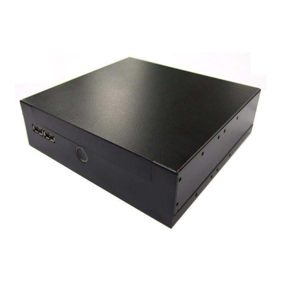
Page 3: Outlook
1. Outlook Front IO Front USB Front USB Power Button Power Button... - Page 4 Rear IO Antenna VGA2 COM port hole Kensington lock hole Mic in HDMI DC 19V VGA1 Line out USB 2.0...
-
Page 5: Open Housing
2. Open Housing 2-1. 2-2. Detach 2 pcs of the rear side screw ( FPH M3 Push the Upper case to remove it . screw ) by the electric screw driver . Front Side (Screwdriver torque : 5.0±0.2 kgf. cm ) Unscrew Rear Side... - Page 6 2-3. Detach 4 pcs of the supporter screw ( FPH 2-4.Remove Supporter M3 screw )by the electric screw driver (Screwdriver torque : 5.0 ±0.2 kgf. cm )
- Page 7 2-5.You will see the kernel of Digital Engine...
-
Page 8: Install Key Components
3. Install Key components 3-1 Install Memory 3-1-1. Insert the memory on the socket as this angle. Insert DIMM as this angle 30°... - Page 9 3-1-2. Then press the DIMM as flat on the Motherboard, and you will hear the click voice. Make sure it clicks...
- Page 10 3-1-3.Unscrew the CPU cooler 3-1-5. Unscrew CPU socket Counterclockwise direction Unscrew 3-1-4. Remove the cooler...
- Page 11 3-1-6 Put the CPU into the socket, and check 3-1-8. Put on the cooler and screw it tightly the direction. . clockwise direction 3-1-7. Screw the CPU socket. 3-1-9 connect the wire for cooler...
- Page 12 3-2 Install HDD on Supporter without ODD 3-2-1 Install Card Holder and screw it with 1pcs of M2 screw. (Screwdriver torque : 0.7±0.1kgf.cm) Put the Card Holder on the supporter, 3-2-2.Insert the MPI-SATA card into HDD Screw internal card to Card holder with 2pcs of M2 screws.(Screwdriver torque:0.7±0.1kgf.cm)
- Page 13 3-2-3. Put the HDD on support 3-2-4. and screw HDD with 4pcs of FPH M3 Please pay attention to the direction of SATA screw (on both flanks) (Screwdriver torque : 2.5 ±0.1 kgf. cm )
- Page 14 3-3 Install HDD on Supporter with slim ODD 3-3-1 Put slim ODD on the top side of supporter, screw the position 1 and 2 with M2 screw first, then screw position 3 and with M2 screw to fix the slim ODD. (Screwdriver torque : 0.7±0.1kgf.cm)
- Page 15 3-3-2.Insert the MPI-SATA card into HDD 3-3-3 Screw MPI-SATA card to ODD with 2 pcs of M2 screws. (Screwdriver torque : 0.7±0.1kgf.cm) and screw HDD with 4pcs of FPH M3 screw 3-3-4. Put the HDD on support Please pay attention to the direction of SATA (on both flanks) (Screwdriver torque : 2.5 ±0.1 kgf.
- Page 16 FPH M2xL3 Screw 3-3-5 FPH M3xL5 Screw...
-
Page 17: Assemble The Supporter & Upper Case
4. Assemble the Supporter & Upper Case 4-1.Make sure Front USB wire connect to MB... - Page 18 4-2. Install the supporter (Only HDD is on the supporter now) 4-2-1. Make sure the MPI-SATA card is correctly insert into the socket 4-2-2.Screw 4pcs of M3 screw at the supporter. (Screwdriver torque : 5.0 ± 0.2 kgf.cm)
- Page 19 4-3. Install the supporter (HDD and ODD are on the supporter now) 4-3-1. Make sure the MPI-SATA card is correctly insert into the socket 4-3-2.Screw 4pcs of M3 screw at the supporter. (Screwdriver torque : 5.0 ± 0.2 kgf.cm)
- Page 20 4-4. Assemble the upper case (without ODD) 4-4-1. Connect the power switch wire. 4-4-2. Connect the Front-USB wire to upper-case. 4-4-3. Adjust the USB cable to arrange the cable under the supporter . Accord the photo.
- Page 21 4-5 Assemble the upper case (with ODD) 4-5-1. Remove ODD door on upper case 4-5-2. Connect the power switch wire. 4-5-3.. Accord the photo Connect the 4-5-4. Adjust the USB cable to arrange the Front-USB wire to upper-case cable under the supporter.
- Page 22 4-6.Screw the upper case 3. Screw 2pcs of M3 screw at rear side (Screwdriver torque : 5.0 ±0.2 kgf. cm )
- Page 23 Without slim ODD With slim ODD...
- Page 24 4-7 Assemble Module of Wireless LAN Mini Card or TV Tuner Mini Card 4-7-1. cable and nut 4-7-2. Note the hole shape to adjust the A,B inside housing; C,D outside housing antenna SMA connector to insert into the hole. 4-7-3. Insert a washer to one end of the 4-7-4.
- Page 25 4-7-5. Detach screw and align the notch to 4-7-6. Install the antenna wire with the button Insert mini card into the slot and fix with screw. of the wireless LAN or TV-tuner Mini card . 4-7-7. Arrange the wire to avoid damaging the 4-7-8.
-
Page 26: Appendix 1 Packing List
Appendix 1 Packing List 1 x DE965-HG system 1 x MPI-SATA card 1 x Easy Assembly Guide 1 x Driver CD 1 x 90W Adapter and Power Cord 1 x Card Holder 1 x L type Holder with 8 pcs of M3 screw 4 x M3 - L5 screws 7 x M2 - L3 screws □... -
Page 27: Appendix 2 Table Of Screw And Torque
Appendix 2 Table of Screw and Torque Screw Photo Position Q’ty Screw spec. Torque Screw driver spec. ♁ Rear side FPH M3- L5 5±0. 2 Phillips #2 kgf-cm ♁ FPH M3- L5 2.5±0. 2 Phillips #2 Length ≧ 8cm kgf-cm ♁... -
Page 28: Appendix 3 Watch Dog Timer Configuration
Appendix 3 Watch Dog Timer Configuration The WDT is used to generate a variety of output signals after a user programmable count. The WDT is suitable for use in the prevention of system lock-up, such as when software becomes trapped in a deadlock. Under these sort of circumstances, the timer will count to zero and the selected outputs will be driven. - Page 29 CODE FLOW-CHART 1. Initial Watchdog Pin (1)set -> Logical Device: Global CR: 0x2D Bit: 0 = 0 WDTO. (2)set -> Logical Device: 0x09 CR: 0X30 Start Bit:3 = 1 activate GPIO5 CR: 0xE0, 0xE1, 0xE2 Bit: 6, Bit: 7, Bit: 6 = 0 GPIO port is programmed as an output port.
- Page 30 1. Set Mode (1)set -> Logical Device: 0x08 CR: 0xF5 Set Min/Sec Mode Bit: 3 = 0 By second = 1 By minute Start Timer 1. Set Mode (1)set -> Logical Device: 0x08 CR: 0xF6 Bit: 7~0 = 0x01 Time- out occur after 1 second/minute = 0xFF Time- out occur after 255 second/minute...
- Page 31 SAMPLE CODE: This code and information is provided "as is" without warranty of any kind, either expressed or implied, including but not limited to the implied warranties of merchantability and/or fitness for a particular purpose. This program just for MB with Winbond W83267DHG LPC I/O 1.
- Page 32 2. Stop Timer 3. Set Min/Sec Mode outportb(0x2E,0x87); outportb(0x2E,0x87); outportb(0x2E,0x87); outportb(0x2E,0x87); outportb(0x2E,0x87); outportb(0x2E,0x87); outportb(0x2E,0x07); outportb(0x2E,0x07); outportb(0x2E,0x07); outportb(0x2F,0x08); outportb(0x2F,0x08); outportb(0x2F,0x08); outportb(0x2E,0xF5); outportb(0x2E,0xF6); outportb(0x2E,0xF7); outportb(0x2F,byBit); outportb(0x2F,byBit); outportb(0x2F,byBit); outportb(0x2E,0xAA); outportb(0x2E,0xAA); outportb (0x2E,0xAA); 4. Start Timer outportb(0x2E,0x87); outportb(0x2E,0x87); outportb(0x2E,0x87); outportb(0x2E,0x87); outportb(0x2E,0x07); outportb(0x2E,0x07); outportb(0x2F,0x08); outportb(0x2F,0x08); outportb(0x2E,0x30);...
-
Page 33: Appendix 4 Outline And Holder Drawing
Appendix 4 Outline and Holder Drawing A. LH01 L type Holder(Include 2 piece holder and 8 FPH M3 screws) L type Holder is a versatile holder, you can You can put on the L type Holder on 2 sides, screw it on any place you want. and screw it tightly. - Page 34 A-3 Dimension of L type Holder. (unit: mm)
- Page 35 B.VM02 Monitor Holder (Include 2 piece holder and 8 FPH M3 and 4 FPH M4 screws) Monitor Holder is base on VESA standard (10cm/7.5cm interval) for you to screw the Digital Engine behind the monitor. You can put on the Holder on monitor VESA mounting hole first, and screw it tightly, then put Digital Engine on VM02 holder and use 4 M3 screws to fix it.
- Page 36 B-2 Dimension of VM02 Monitor Holder (unit: mm)
- Page 37 C. ST01 Vertical Holder (Include 2 piece holder and 8 FPH M3 screws) You can put the Digital Engine Vertical with the You can put the stand(s) on right side, and holder screw it tightly.
- Page 38 C-3 Dimension of Vertical Holder. (Single Stand) (unit: mm)
- Page 39 C-4 Dimension of Vertical Holder.(Double Stand) (unit: mm)
- Page 40 D. Dimension of DE965-HG (unit: mm)
- Page 41 Safety Note: 1. Unplug AC Power Cord before setup HDD 2. HDD needs to meet maximum rating below 5Vdc / 1.5A max; 12Vdc / 1.5A P/N:49.ADE01.0520 S/N:088-033-127...
Need help?
Do you have a question about the Digital Engine DE965 and is the answer not in the manual?
Questions and answers