Table of Contents
Advertisement
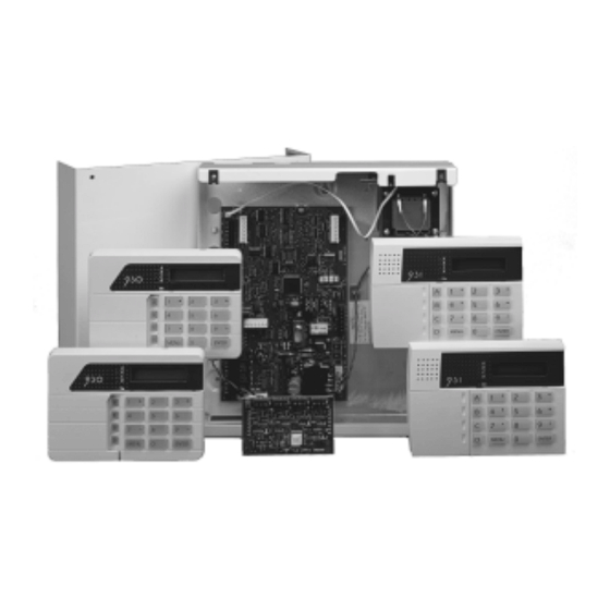
Installation and User Guide
Compatible Equipment
941
Single Loop IDIS zone expander
card
942
Four Loop IDIS zone expander
card
943
8 zone FSL plug-on Zone
Expander
930
32 character LCD Remote
Keypad
(new style large keys)
931
32 character LCD Remote
Keypad
new style case.
947
Portable printer (Battery powered)
and power supply unit
949
Wall Mounted Printer Bracket
956
Scantronic high speed <Down-
loader> PC based software
951
Printer lead
9040
16 Ohm internal sounder
9056
Plug-on Digital Communicator
Plug-on RedCare STU
(manufactured by others)
9076-01/02 Signalling Interfaces
901
Wired IDIS Module (Pack of 5)
903
Mains switching (AC) relay I/O
IDIS boxed interface
8136UK-50/75
496339 Issue 4
904
Low voltage relay I/O
IDIS boxed interface
905
IDIS LIM (5x 4wire CC in
5x 0C outputs (100mA each)
906
(Obsolete) IDIS SCB Module
907
IDIS Power Supply
908
IDIS Line Interface Module
915/916
IDIS PIRs
920
IDIS Twintech (multi-beam
domestic)
921
(Obsolete) IDIS Twintech (multi-
beam commercial)
922
(Obsolete) IDIS Twintech (long
range commercial)
923
IDIS Twintech (360° ceiling
mount)
935
(Obsolete) IDIS 20mm Door
Contact
944
IDIS Hand-held Programmer
8136EUR-02
17AH Large Capacity battery kit
8136UK-75 RedCare Ready kit
1 of 44
Advertisement
Table of Contents

Related Manuals for Scantronic 8136UK-50


Summary of Contents for Scantronic 8136UK-50
-
Page 1: Compatible Equipment
Portable printer (Battery powered) (Obsolete) IDIS Twintech (long range commercial) and power supply unit IDIS Twintech (360° ceiling Wall Mounted Printer Bracket mount) Scantronic high speed <Down- (Obsolete) IDIS 20mm Door loader> PC based software Printer lead Contact IDIS Hand-held Programmer 9040... - Page 2 IDIS zones. IDIS is the proprietary three wire point detector identification system devel- oped for Scantronic Limited. Each IDIS zone can connect an IDIS detector or, by using an IDIS interface module, a standard detector and output. IDIS minimises wiring costs since all detectors can share a single 3-wire cable.
- Page 3 8136 Keypads Keypads The 931 Keypad The 8136 is supplied with the 931 low profile keypad, shown in Figure 1. Level A to D LEDs (Set or Unset) 32 Character plain text Liquid Crystal Display Power Optional programmable panic alarm keys. Press Scroll and Level keys 1 and 3 together setting keys...
-
Page 4: Technical Specification
Technical Specification 8136 Figure 3 shows the keypad PCB used in the 930 and 931. Note the position of the Test and Prog switches, and the keypad sounder volume control. Prog and Test Sounder Volume Back of display Control Prog Test Sounder Key area... -
Page 5: Keypad Wiring
8136 Battery Siren = 750mA. Batt (reverse connection) = 2,500mA. OP1, OP2, OP3, and OP4 are voltage free, single pole relay contacts rated 24VDC @ 3A. Battery Recommended Standby Battery = 12 Volt, 7.0AH (min) 17AH (max) re- chargeable lead-acid, Gel Type battery. Battery Space = h x w x d 190 x 205 x 75mm. -
Page 6: Keypad Address
Keypads 8136 • A minimum of four outputs provided by the end station PCB up to a maximum of 132, with the extra 128 provided by each IDIS zone. • Six Flexi-Zones per Level. • 95 User codes, including one Supervisor. •... - Page 7 8136 Wiring Press ‘Menu’. The display shows the current status of the keypad back-light: 0 for timed or 1 for back-light always ‘ON’, for example: 3: 1 Change the back light status as required by entering 0 or 1 10. Press ‘Menu’. The display shows the current status of the keys: 0 for Active or 1 for Inactive, for example: 4: 0...
- Page 8 Wiring Keypads 8136 The 8136 main PCB has facilities for connecting: Fifteen keypads. Eight 2-wire FSL detector zones. Siren (4-speaker 16 ohm). Four outputs. If you wish to connect extra detector zones you can fit either an eight zone FSL Expander Card, or 32- or 128- zone IDIS Expander Cards. Figure 4 shows the main connector on the 8136 PCB.
- Page 9 8136 Wiring FSL Detectors Wiring FSL Detectors Each FSL zone is a ‘Fully Supervised Loop’ using a two wire closed loop. The loop uses two resistors of different values to differentiate between ‘Circuit’ and ‘Tamper’ signals: a 2K2 (2.2K ) resistor fitted in series at the end of the wired loop (EOL-End-Of-Line), and a 4K7 (4.7K ) resistor fitted across the alarm contact, see Figure 6.
- Page 10 Wiring IDIS Detectors 8136 Wiring IDIS Detectors If you wish to use IDIS sensors, then you must fit an IDIS Expander card to the end station main PCB. Figure 8 shows the layout of an IDIS expander card. 942 IDIS Expander 941 IDIS Expander IDIS Loop 4 zones 105 - 136...
- Page 11 8136 Programming Initial Power Up Battery Only (Kick Start) When powering the end station from a battery for programming and testing short out the ‘Kick Start’ pins with a small screwdriver to connect the battery and allow operation of the system. The pins are located to the bottom right of the main PCB adjacent to the battery connection and are marked ‘KICK START’.
- Page 12 Finding Menu Items 8136 Finding Menu Items The 8136 programming is divided into sets of numbered menus. Each menu starts with a two digit number. The menus are grouped together into the following categories: Menu No Category Start point for Installer programming. 01, 04, 09 Software version, Testing, and Printing.
- Page 13 8136 Programming Chart 00:PROGRAM 01:DISPLAY PANEL 04:TEST OPTIONS SYSTEM VERSION NUMBER ENTER ENTER Show software version SELECT TEST WALK TEST SELECT TEST OUTPUT TEST SELECT TEST Test keypad, sounder and SOUNDER TEST speaker SELECT TEST ZONE TEST Select zones, display zones status ENTER SELECT TEST...
- Page 14 Programming Chart 8136 09:PRINT OPTIONS ENTER PRINT EVENT LOG? Print all, or individually: PRINT CONFIG keypads, area/partitions, levels, zones, outputs, system, communications. 70: PROGRAM COMMUNICATIONS ENTER Dial Type 71: COMMUNICA- Call Mode TIONS OPTIONS Disabled Single NOTE: Dual Except where shown, move between menus by using Alternate menu numbers, or the up and down keys.
- Page 15 8136 Changing Menu Items Changing Menu Items After selecting a menu, press Enter to see further options belonging to that menu. The system usually displays the name of the option on the top line, and the values the option currently has on the bottom line of the display. In addition, the system shows a flashing cursor to mark the part of the display that will change when you next press a key.
- Page 16 Leaving Programming Mode 8136 If you make a mistake, use the left or right arrow keys (C or D) to move the cursor over the letter you want to change, and key in the new letter. If you want to delete a name completely, use the left arrow key (C) to move the cursor under the extreme left hand character of the name.
- Page 17 8136 Re-entering Programming Mode Press Menu. If the end station lid is open, the displays shows:REPLACE END STATION LID Close the end station lid. If no faults are present the display shows the time and date: WED 15 JAN 1998 09:25 If faults exist, the display will show, for example: CANNOT EXIT ENG 02 FAULTS EXIST...
-
Page 18: Engineer Reset
Engineer Reset 8136 Engineer Reset If you wish to perform an Engineer Reset without removing the end station lid, type-in 0 (zero) + Engineer Code, (default 7890) then press Enter. Resetting User and Installer Codes If the installer and/or user codes have been lost, or you need to return the end station to the factory default access codes, you can load the default codes as follows: Disconnect mains and battery power to the system. - Page 19 (The system may display the PLEASE WAIT message for several seconds while it loads defaults.) The end station now has the full set of Scantronic factory defaults (including 4 digit access codes) and needs reprogramming. Note: If you remove power during programming, and you have not created a valid configuration, then the system will force you to enter programming mode when you reapply power.
- Page 20 Programming for IDIS 8136 Note: When programming IDIS devices with their intended zone numbers, make sure that only one IDIS device is connected to the Expander at a time. If necessary disconnect the Sig lead to all other IDIS devices except the one that is being programmed.
- Page 21 8136 Programming for IDIS OR: For interfaces or SABs with a 2-pin PROG connector use a 3-way to 2- way Molex to Molex lead 485208. Connect the 2-pin Molex end onto the pins marked 'PROG' on the device. Ensure that the BLUE lead is located on the pin marked with a star (*).
- Page 22 Try again to program the module. If you do not succeed then use a new device and return the original to the manufacturer. NON SCANTRONIC The module is not a Scantronic IDIS device. The module cannot be used. 22 of 44 496339 Issue 4...
-
Page 23: Programming Zones
8136 Factory Defaults Programming Zones ZONE AREA ATTRIBUTES C = CHIME O = OMIT ALLOWED Z01: A C O D T ZONE No. D = DOUBLE KNOCK T = TEST NA 2 N Y N N ZONE TYPE Y = ACTIVE N = INACTIVE AREA No. -
Page 24: Factory Defaults
Factory Defaults 8136 Factory Defaults When delivered from the factory, the 8136i is preprogrammed with the following default settings: System Users UO1: Name = User 01, Access Code 1234, Authority Level A,B,C,D, System Full Use, Zone omit Permitted, Log Access = Permit- ted, Change Area and Zone names = Permitted, Change Data and Time = Permitted, Reset = Permitted User 02-95:... - Page 25 8136 Working with <Downloader> Menu 61: Installer information = Code = 7890, Name = Installer, Service telephone number = Call Engineer, no telephone number Menu 62: PA response = Audible Menu 63: Line Fault response = Audible Menu 64: Allow Zone omits = Disabled Menu 65: System reset = Customer (PA reset = Customer) Menu 66:...
- Page 26 Working with <Downloader> 8136 • Use Menu 73 to set up automatic answering to a remote PC. • Use Menu 66 to manually control the system when the remote PC calls for the first time. Note that Menu 66 can also be used at the system site to control contact with a local PC (for example a laptop PC).
- Page 27 8136 Connecting to a Remote PC for the First Time the alarm system number, waiting for between one and two rings and then hanging up. The alarm system now knows to expect a call within the next 10 to 90 seconds. Downloader then rings the alarm system again, within 10 to 90 seconds.
- Page 28 “Call Out” to a Downloading Computer 8136 When the Remote PC has completed downloading and signed off, the display shows: DOWNLOAD COMPLETE followed by Menu 66. Connecting a Local PC to Use Downloader (Menu 66). The serial port can also by used as a link between a local PC and the sys- tem.
-
Page 29: Fault Finding
8136 Fault Finding The display shows: SERIAL OUTPUT PRINTER Use the up or down arrow keys to select Local PC. Press Enter to confirm your choice. The display shows: REMOVE PRINTER CONNECT PC Connect the cable from the local PC to the serial port, and link up the PC to the panel using the local PC option on the Downloader software. -
Page 30: Error Messages
Error Messages 8136 General Faults No response from the keypad keys. • Check the keypad wiring. • Check the keypad address programming. See "Keypads". • Enter and leave programming mode. • Power up while shorting RST pins. (See "Resetting User and Installer Codes".) No exit/entry tones from remote keypad •... - Page 31 8136 Configuration Checking Error Messages AREA 04 NO P Meaning: Area Not Assigned to Partition. In the example shown, Area 04 has a zone type programmed, but has not been assigned to a Partition. All programmed Areas must be Assigned to one Partition. Action: Check Menus 32 and 35.
- Page 32 FSL Zone Status Error Messages 8136 NON KEY Z IN LA Meaning: No Keyswitch Zone In Level. In the example shown Level A has been assigned a keyswitch zone which is not a keyswitch zone type. Action: Check Menu 41 or 32. KEYSWITCH ZONES Meaning: Keyswitch Zone Assigned to Different Levels.
- Page 33 8136 Simple Test Method IDIS Fault Finding If the IDIS system is programmed and connected but either doesn't work correctly or is inconsistent then this section describes steps you can take to isolate the fault. Work on one loop at a time to avoid confusion. Faults on one IDIS loop do not affect other loops provided you have not linked the loops remote from the panel.
- Page 34 Simple Test Method 8136 If you have a fault that is intermittent, or cannot be traced easily, then always prove the main equipment first by changing it before starting extensive fault finding. Simple Test Method Try replacing the module or LIM with another, programmed to the same address.
- Page 35 NON SCANTRONIC The module is not a Scantronic IDIS device. The module cannot be used. Check the current readings from the module. Table 4 shows a list of possible readings.
- Page 36 Improving the Voltage Drop 8136 Table 4. IDIS Module Current Readings Circuit Reading Meaning A1 (Tamper) 1.5mA Tamper loop shorted to 0V. Open tamper circuit. 3-4mA Potential tamper fault. 4-5mA Voltage drop on 0V line. 5-6mA Good (closed) circuit. A2 (Alarm) Open alarm circuit.
- Page 37 8136 Fitting a PSU If faults are still present then split the IDIS loop into three or four smaller sections. Try each section in turn, reinitialising each time. (Allow for missing zones). See if you can isolate the faults to one section of the loop.
- Page 38 Electrical Noise 8136 IDIS Sensor IDIS Sensor IDIS Sensor IDIS Sensor IDIS Expander Card +12V IDIS Sensor IDIS Sensor IDIS Sensor +12V +12V Remote Power Supply Figure 14. Siting IDIS remote PSU If the sensors are more or less evenly spaced along the wire an ideal split is to allow the panel to run a third of the sensors (those nearest it).
- Page 39 8136 User Facilities Electrical Noise The IDIS system is very robust with regard to electrical noise but running the IDIS bus for long distances tied close to single, three phase electrical, or data cables is not advised. Cables for electrical machinery are particularly bad and should be kept at least 0.2m away if at all possible.
-
Page 40: Operating The System
installer Setting 8136 User 00 The Installer or Engineer. User 96 The central station when it carries out a remote reset. User 97 The control panel when it performs an internal check (watchdog). User 98 Any keyswitch. User 99 <Downloader> when it connects to the system. Operating the System Users can set and unset the system from a keypad using one of the following key sequences:... - Page 41 8136 Installer Setting Users can reprogram limited parts of the system. The 8136 provides the following set of user menus: Menu 1: Setting with omissions. Menu 2: Omit 24 hour zones. Menu 3: System Options, including Enable/Disable Chime, adjust the internal sounder volume, and Enable/ Disable Remote Set/Unset from a PC.
-
Page 42: Access Code
User Menu Chart 8136 Access Code + Access Code + Access Code + Access Code + Menu + 1 Menu + 3 Menu + 5 Menu + 6 6: SET TIME AND 1:SETTING 3: SYSTEM 5:ANSWER REMOTE DATE WITH OMISSIONS OPTIONS CALL FROM CS? ENTER... - Page 43 8136 User menu Chart Access Code + Access Code + Menu + 8 Menu + 7 (Supervisor and restricted access for Master User) 7:CHANGE AREA & 8:USER ZONE NAMES? INFORMATION ENTER ENTER EDIT USER CHANGE CHANGE INFORMATION? ZONE NAME? AREA NAME? ENTER ENTER ENTER...
- Page 44 44 of 44 496339 Issue 4...
Need help?
Do you have a question about the 8136UK-50 and is the answer not in the manual?
Questions and answers