Table of Contents
Advertisement
Advertisement
Table of Contents

Related Manuals for Scantronic 9800


Summary of Contents for Scantronic 9800
-
Page 1: User Guide
Microprocessor Intruder Alarm System User Guide SCANTRONIC L TD... -
Page 2: Glossary Of Terms
Glossary of Terms Access Code User private code (4 Digit) used to set, unset and programme the system. Automatic An optional automatic dialling unit fitted within the Signalling Device alarm control unit and connected via your telephone line to your alarm company central station. Bell-Walk Test A routine test of all alarm detectors and warning devices. -
Page 3: Table Of Contents
Contents Section Title Page INTRODUCTION ....... . .2 OPERATOR CODES AND DISPLAYS ....3 OPERATOR CODES . -
Page 4: Introduction
Introduction The 9800 Electronic Intruder Alarm system uses the latest microprocessor technology to provide a simple to operate, yet highly flexible system, suitable for a wide range of small to medium sized protection applications. The system comprises a main control unit, housing the system control printed circuit board and power supplies. -
Page 5: Operator Codes And Displays
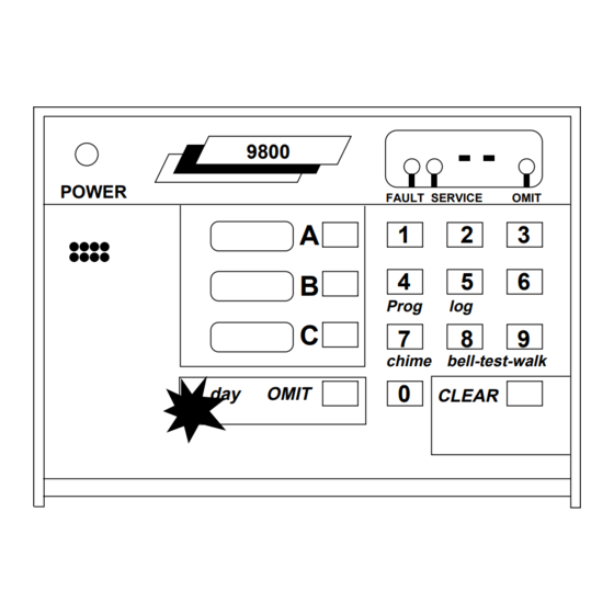
Operator Controls and Displays LED Display Complete System Fault LED Omit LED Service LED Program Button Selector Button Mains LED 9 8 0 0 Numeric Keypad POWER Keypad FAULT SERVICE OMIT Sounder System Prog log Indicators chime bell-test-walk Log Button d a y OMIT CLEAR... -
Page 6: Normal Setting
Normal Setting Ensure that all doors and windows are secure, check that movement detectors are not obstructed and proceed as follows: 9800 9800 POWER POWER FAULT SERVICE OMIT FAULT SERVICE OMIT Prog Prog chime bell-test-walk chime bell-test-walk OMIT OMIT CLEAR CLEAR Enter access code. -
Page 7: Setting With Zones Open
Should the user attempt to set the system with one or more zones open, the system will not set. The internal sounder will emit an interrupted tone and the LED display will indicate the open zone, proceed as follows: 9800 9800 POWER... -
Page 8: Keyswitch Setting
NORMAL KEYSWITCH SETTING The following describes setting the system using the keyswitch and the response of the keypad. 9800 POWER FAULT SERVICE OMIT... - Page 9 Should the user attempt to set the system with the keyswitch when one or more zones are open, the system will not set. The internal sounder will emit an interrupted tone and the LED display will indicate the open zone. Proceed as follows: 9800 POWER FAULT SERVICE...
-
Page 10: Part Setting
The Part Set function provides the user with the facility to set the system with only the detection allocated to Group B or C being armed. Circuits not allocated to a Part Set group will not be armed when setting, allowing normal access. 9800 9800 POWER POWER... -
Page 11: Setting With Zones Omitted
The user can set or part set the system with selected alarm zones omitted from the system. (If zone is programmed by engineer for ‘Omit Enabled’.) However certain zones, classified as ‘Non Omit’ cannot be omitted. To set the system with zone(s) omitted, proceed as follows: 9800 9800 POWER POWER... -
Page 12: Omitting A 24Hr Zone
Omitting a 24Hr Zone If necessary, the user can omit a 24hr circuit when the system is unset. (If zone is programmed by engineer for ‘Omit Enable’.) To omit a 24hr circuit proceed as follows: 9800 9800 POWER POWER FAULT... -
Page 13: Unsetting The System
Unsetting the System On entering the premises the sounder will be emitting a continuous tone. The user should proceed immediately to the keypad via the prescribed entry route and unset the alarm as follows: 9800 9800 POWER POWER FAULT SERVICE... -
Page 14: Straying From The Entry Route
Your system may be programmed with an ‘Abort’ feature, which works as follows: The 9800 gives a full alarm if the user leaves the entry route or exceeds the entry time. The 9800 sends a ‘Restore’ signal to the central station if the user enters a valid access code at the keypad within 90 seconds of the alarm (avoiding Police action). -
Page 15: Remote Reset
This ensures that the user contacts the central station to acknowledge accidental alarms or system problems. If the alarm has activated following a genuine intrusion, procedural error or for other reasons, proceed as follows: 9800 9800 POWER POWER FAULT... - Page 16 Remote Reset (Cont.) Call your alarm company central 9800 station, follow the verification POWER FAULT SERVICE OMIT procedure (usually a code name or number) and give the ‘Control Code’. You will then be given a 4 Prog digit ‘Reset Code’.
-
Page 17: Unsetting After An Alarm
Unsetting After an Alarm On entering the premises following an intrusion, a full alarm condition will exist. To cancel the alarm, the user should proceed directly to the remote keypad via the prescribed entry route and proceed as follows: 9800 9800 POWER POWER... -
Page 18: Chime Setting
‘Chime’ tone if any normal alarm, entry route or final door zone is opened. Where an exit terminator is fitted, this will act as a door bell when the system is set to chime. To set the system to chime, proceed as follows: 9800 9800 POWER POWER... -
Page 19: Changing Access Codes
The system will accept up to four different user access codes, the first of which is pre-programmed. The user can allocate or amend all four codes at any time, or amend the ‘Duress’ code as follows: 9800 9800 POWER POWER... -
Page 20: Reviewing The Event Log
With the alarm system in the ‘Day’ state, the user can scan the coded event log to obtain a record of system events. The event log will display events chronologically, with the most recent event first. To scan the event log, proceed as follows: 9800 9800 POWER POWER... -
Page 21: Sounder, Bell & Strobe Test
Sounder, Bell & Strobe Test The user can test the operation of the internal and external sounders, bell and strobe as follows: 9800 9800 POWER POWER FAULT SERVICE OMIT FAULT SERVICE OMIT Prog Prog chime bell-test-walk chime bell-test-walk OMIT OMIT... -
Page 22: System Walk Test
System Walk Test The user can ‘Walk Test’ the system and test the operation of each detector circuit (with the exception of panic alarms or fire circuits) as follows: 9800 9800 POWER POWER FAULT SERVICE OMIT FAULT SERVICE OMIT Prog... -
Page 23: System Faults And Alarm Conditions
TELEPHONE LINE FAULT If your system is fitted with a remote signalling device which operates over the standard telephone network, a local alarm condition will warn the user if a telephone line fault exists as follows: 9800 9800 POWER POWER... - Page 24 System Fault Conditions (Cont.) BATTERY FAULT If a battery fault condition occurs when the system is unset, a local alarm condition will be initiated. To cancel the local alarm, proceed as follows: 9800 9800 POWER POWER FAULT SERVICE OMIT FAULT...
-
Page 25: Daytime Tamper Alarm
However, if the tamper alarm occurs when the system is unset, a local alarm only will be initiated. Check for any obvious causes and then cancel the alarm as follows: 9800 9800 POWER... -
Page 26: Explanation Of Codes
Explanation of Codes c1 to 8 Detector circuit open. t1 to 8 Circuit tamper open. o1 to 8 Detector circuit omitted (isolated). E1 to 8 Entry via a detector circuit. S1 to 8 Detector circuit on Soak test. Alarm on entry Exit fault Control panel battery fault Mains supply failure. -
Page 27: Your Circuit Description
Your Circuit Description ZONE DESCRIPTION WHOLE PART PART OMIT CHIME SYSTEM SET B SET C ALLOWED Installed by (Engineer’s signature) ....Date Completed ... . . ENGINEER RESET . -
Page 28: Service Record
Service Record DATE REPORT... -
Page 29: Service Contact
Your Service Contact COMPANY NAME ........ADDRESS . - Page 30 Manufactured in the UK by Scantronic Ltd. Pt. No. 495665 Issue 2 SCANTRONIC L TD...
Need help?
Do you have a question about the 9800 and is the answer not in the manual?
Questions and answers
electrical work at home has left us with Sr error code on our scantronic 9800 alarm system - how do we clear?
The "Sr" error code on a Scantronic 9800 alarm system stands for "System Restart," which means the system was completely powered down and then turned back on. To clear this error, you may need to reset the system using the engineer/installer code. If you do not have this code, a professional installer may be required. Additionally, if the battery is faulty or fully discharged, replacing it and servicing the system may be necessary.
This answer is automatically generated
WHAT IS E7