Table of Contents
Advertisement
Available languages
Available languages
Quick Links
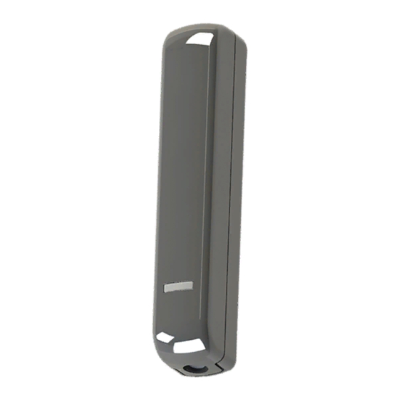
DET-RSDC
Installation Instructions
UK
Guide d'installation
FR
Installatiehandleiding
NL
Fig. 1: DET-RSDC
Fig. 2: Cover removal /
Abnehmen der Abdeckung /
Dépose du cache /
Rimozione del coperchio /
Deksel verwijderen
Fig. 5: Mounting locations / Montagepositionen / Emplacements de montage / Sedi di montaggio / Locaties bij montage
Align with arrows on magnet
backplate.
Mit Pfeilen auf Rückplatte des
Magneten ausrichten.
Alignez avec les flèches sur la
plaque arrière de l'aimant.
Allineare con le frecce sulla
base posteriore del magnete.
Centreer met pijlen op
grondplaat van magneet.
Important!
Wichtig!
Important!
Importante!
Belangrijk!
Fig. 6: Mounting the sensor / Montage des Sensors / Montage du détecteur /
Montaggio del sensore / Sensor monteren
Scantronic
3
SENS
2
LED
1
Fig. 3: PCB / Leiterplatte / PCB /
PCB / Printplaat
3
Installationsanweisungen
DE
Istruzioni per l'installazione
IT
5mm
MODE
+
Tamper /
Sabotage /
Autoprotection /
Interruttore anti-
manomissione /
Sabotage
Fig. 4: Mounting distances / Montageabstände /
Distances de montage / Distanze di montaggio /
Afstanden bij montage
1
2
Fig. 7: Mounting the magnet / Montage des
Magneten / Montage de l'aimant / Montaggio
del magnete / Magneet monteren
10mm (0-20mm)
10mm max on metal surface;
15mm max on non-metal.
max. 10 mm auf
Metalloberfläche; max.
15 mm auf Nicht-Metall.
10 mm max sur surface
métallique; 15 mm max sur
surface non métallique.
10 mm max. su superfici
metalliche; 15 mm max. su
superfici non metalliche.
Max. 10 mm op metaal; max.
15 mm op niet-metaal.
Fit the magnet
Magnet anbringen
Montez l'aimant
Montare il magnete
Monteer de magneet
Advertisement
Table of Contents

Subscribe to Our Youtube Channel
Related Manuals for Scantronic DET-RSDC


Summary of Contents for Scantronic DET-RSDC
- Page 1 / Sabotage Max. 10 mm op metaal; max. 15 mm op niet-metaal. Fig. 1: DET-RSDC Fig. 2: Cover removal / Fig. 3: PCB / Leiterplatte / PCB / Fig. 4: Mounting distances / Montageabstände / Abnehmen der Abdeckung /...
- Page 2 Eaton selling routes), which can reduce installation time policies or other contractual agreement between Eaton 2. Open the DET-RSDC, then press and release and cost. and the purchaser. the tamper switch five times within three...
- Page 3 Einleitung für schwache Batterie 2,4 VDC. Typische Lebensdauer: 1,5 Jahre. Den Sensor testen Das DET-RSDC ist ein Funkgerät mit Dual- Strom: 20µA (Ruhezustand); max. 25 mA. Technologie, das zwei Sensoren enthält: Funktion des Geräts testen. Die LED (sofern einen magnetisch betätigten Reedschalter zur Funk: 868,6625 MHz;...
- Page 4 1. Allez dans le menu d’installation. Identifiez le détecteur du type DET-RSDC est conforme à la directive 2014/53/UE. Le texte complet de la 2. Ouvrez le DET-RSDC, puis appuyez et 1. Placez le DET-RSDC près d’un clavier.
- Page 5 Il LED (se abilitato) lampeggia quando uno dei due sensori si attiva. Dopo il test, si Dimensioni del magnete (A x L x P): 55 x 12 Il DET-RSDC è un dispositivo radio a duplice consiglia di rimuovere il ponticello del LED per x 12 mm.
- Page 6 LED). gebruik van apparatuur, centrale of elektriciteitssysteem, infrarood (geen radiosignaal) ingeleerd. kapitaalkosten, stroomverlies, extra uitgaven bij het Richt in dat geval de DET-RSDC LED op de EN 50131-2-6,5.2,c) gebruik van bestaande stroomfaciliteiten of claims inleersensor van de ontvanger (LED-link moet...
- Page 7 Page 7...
- Page 8 Part number 12997425 Issue 1 06/02/20 Page 8...
Need help?
Do you have a question about the DET-RSDC and is the answer not in the manual?
Questions and answers