Advertisement
Introduction
The 9800+ (16 zone) System
The 9800+ (16 zone) system comprises a control unit, one or more keypads, and various detectors.
The control unit is a steel box that houses the main controller, power supply, stand-by battery, and any remote communicator. The control unit is normally fitted out of sight in a safe place (for example under the stairs).
The detectors are installed at various places, or zones, around the premises. If something triggers a detector then it signals back to the control unit. How the control unit reacts depends on whether the system is set or unset.
When set the system raises an alarm whenever a detector is triggered. The alarm might be a bell or strobe on the outside of your premises, or it might be a silent signal over the telephone line to a central monitoring station. When unset the system does not raise an alarm if a detector is triggered.
The system provides three different setting Levels, labelled A, B, and C. Level A sets the whole system, protecting all of the premises covered by the alarm system. Levels B and C set part of the system, protecting part of the premises while the rest is in use. The system raises an alarm when a detector belonging to a set Level is triggered. The Installer programs the Levels during installation. Ask your Installer to tell you which zone is allocated to each Level.
Your premises may be fitted with 24 hour zones and panic alarm zones. If these zones are triggered the system will raise an alarm whether or not any Level is set.
The Keypad
From the keypad you can set and unset the system, read the event log, and make minor changes to the way the system operates.
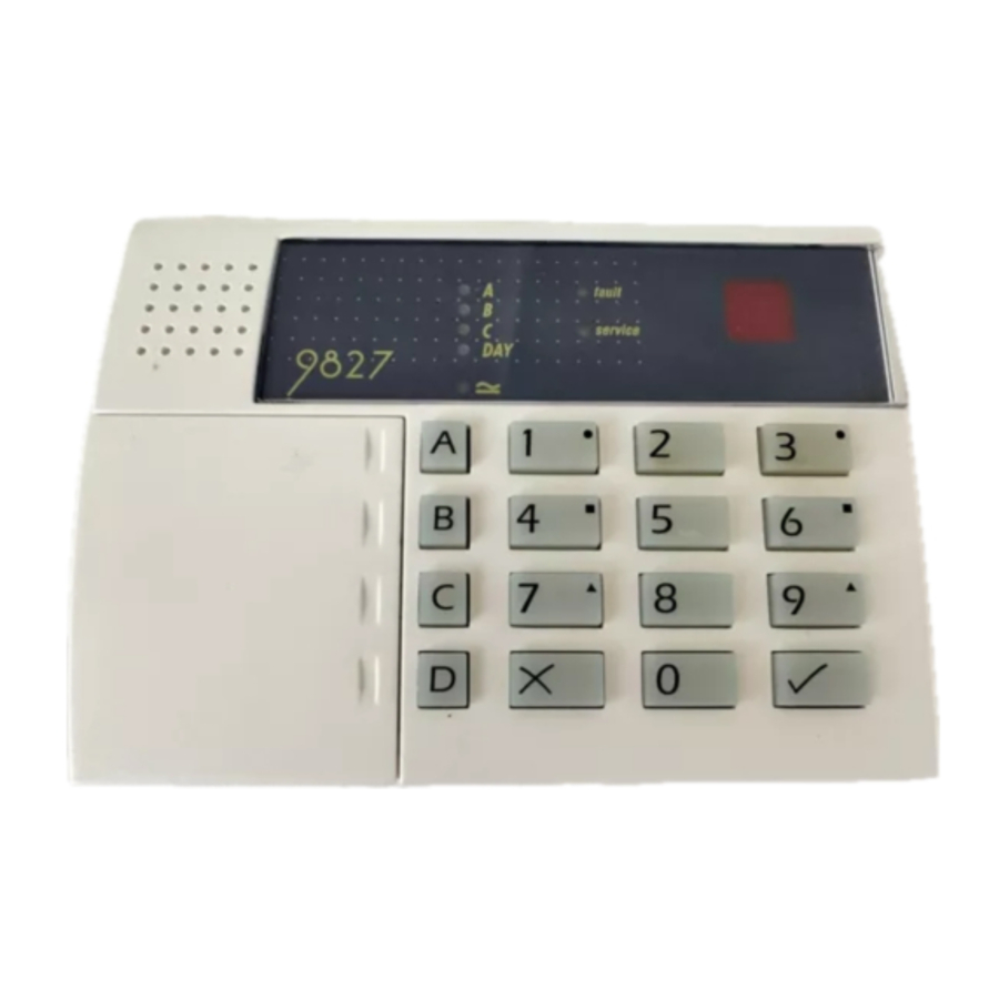
You must enter an access code before the system will accept commands from the keypad. The system can store up to 8 different access codes, providing secure access for 8 users. Figure 1 below shows the keypad in detail.

Figure 1. 9800+ Keypad
The keypad has the following displays and controls:
| A, B, C LEDs | These LEDs (Light Emitting Diodes) glow to show which Level is set. The LEDs are dark when the Levels are unset. Note that the installer can program the system to hide the display. |
| Day LED | The Day LED glows when the system is unset. The LED goes dark when the system is set. Note that the installer can program the system to hide the display. |
| Fault LED | The Fault LED glows when the system is in alarm, if the system has detected a fault on the telephone line, or if the internal battery has failed. |
| Service LED | The Service LED glows when the panel needs an engineer to reset it, or the system has detected an internal problem. Call your alarm installer. |
| Power LED | The Power LED glows when the system is using mains power. If the Power LED flashes slowly then the mains power has been disconnected and the system is running off the stand-by battery. |
| LED Display | The system displays information and instructions through the two character LED display. |
| Level Setting Keys | Use these keys to set individual Levels. A sets the whole system. B and C set part of the system. (D is not active.) Note that you will have to use your access code first. |
| Panic Alarm Keys | Press keys 1 and 3 together to raise a personal attack alarm. (Check with your Installer that your system is programmed with this function.) |
| 3 (Clock) | Press 3 to change the time and date stored in the system * |
| 4 (Code) | Press 4 to change access codes. * |
| 5 (Log) | Press 5 to read a record of events that have |
| 7 (Chime) | occurred on your system. * Press 7 to switch the Chime function on or off. * |
| 8 (Bell test) | Press 8 to start a bell test. * |
| 9 (Walk test) | Press 9 to start a walk test. * |
| X (Omit) | The X key (Omit on 9800 keypads) lets you omit (bypass) zones when setting the system. Note that the Installer must program individual zones so that the system will allow you to bypass them. |
 (Clear) (Clear) | The y key (Clear on 9800 keypads) tells the system that you have finished entering an access code (or other command). |
* (see "Special Functions")
About This Guide
The rest of this guide tells you how to use the system in more detail:
- Everyday Operation
Describes how to set and unset the system. - After an Alarm
Tells you how to switch off the sounders after an alarm, how to see what caused the alarm, and how to reset the system so that it can be used again. - Special Functions
Tells you how to use the more advanced features of the system. - System Faults
Tells you what to do if the alarm system reports a fault.
Everyday Operation
There are several different ways of setting the system. For all methods (except using a Keyswitch) you must enter your access code at the keypad. The Keyswitch method uses a key in a special switch fitted to your premises. "Setting the System" below describes each method. Ask your Installer to provide the method that suits your site best.
During installation the Installer programs the system to create an exit route for your premises. When setting the system you must follow this route to leave the premises. Similarly you must follow a specified entry route when going into the premises in order to unset the system. If you stray from these routes you may cause a false alarm.
How Do I Know if the System is Working?
The Power LED always glows when the mains power is present. If the Power LED flashes slowly then mains power is off, and the system is working from its internal battery. If the Power LED is dark then the system is dead.
When the system is set, a Level LED glows to show which Level key was used. When the system is unset, the Day LED glows. However, the Installer can program the system to hide these displays. Ask your installer how the system is set up.
If you wish to test the system and its detectors, see "Special Functions - Testing the System".
Setting the System
Timed Final Set
With Timed Final Set the system sets after a programmed exit time has expired. Ask your Installer to make sure the exit time is long enough for you to leave the premises and close the final door.
- Close all doors and windows.
- Key in your access code at the keypad.
- Press the appropriate Level key. The exit time starts when you press the Level key. During the exit time the Level LED flashes and the keypads give a continuous exit tone to warn you that the timer is running.
If you hear an interrupted tone from the keypads or internal sounder then one of the detectors is operating. The keypad shows the zone number of the detector. Make sure that all doors and windows are closed.
- Leave via the designated exit route. Close the final door. At the end of the exit time the system sets, and stops the exit tone. The Level LED glows steadily to show which Level is set.
 Note: If you change your mind about setting the system either press
  (Clear) within five seconds of entering your code, or key in your access code again if you or miss the first five seconds.
Exceeding the Exit Time
If you do not close the final door before the end of the exit time then the system gives an alarm and does not set. You can cancel this false alarm by entering your access code at the keypad immediately.
When you have cancelled the alarm you will have to reset the system and restart the setting procedure.
Final Door Set
With Final Door setting the system sets when you close the last door. There is no fixed exit time.
- Close all doors and windows.
- Key in your access code at the keypad.
- Press the appropriate Level key. The keypad starts the continuous exit tone and the Level LED flashes.
- Leave via the designated exit route and close the final door.
Exit Terminate Button Set
In Exit Terminate Button setting the system completes setting after you press a button mounted outside the premises by the final door.
- Close all doors and windows.
- Key in your access code at the keypad.
- Press the appropriate Level key. The keypad starts the continuous exit tone and the Level LED flashes.
- Leave via the designated exit route. Close the final door.
- Press the exit terminate button. The exit tone stops and the system sets. The Level LED glows steadily.
Note: The Installer may have programmed your system to set after a fixed time even if you do not press the exit terminate button. This is to make sure your premises are protected even if you forget to press the exit terminate button. Ask your Installer how your system is set up.
Part Setting
The Installer may have programmed your system so that you can protect part of the premises while the rest is in use. Level keys B and C can give two part set areas, ask your installer which areas each key covers.
- Close doors and windows in the protected area.
- Key in your access code at the keypad.
- Press the Level key B or C as necessary. The keypad starts the continuous exit tone and the Level LED flashes (see "Instant Set" below).
- Leave via the designated exit route and if necessary close the final door. The exit tone stops and the system sets. The Level LED glows steadily to show which Level is set.
Note: Some Levels on your system may be programmed for Silent Set. When setting these Levels the system does not give any tones from the keypads or intemal sounder.
Instant Set
The area protected by a part set system may not need an exit route or final exit door. For these areas the Installer may program the Level key protecting the area as Instant Set. With Instant Set the system sets as soon as you press the Level key. Note that Instant set is only available on level keys B and C.
Keyswitch Setting
- Close all doors and windows. The Ready lamp on the keyswitch should be glowing to indicate that all the detectors are closed. (Some types of keyswitch do not have lamps.)
- Turn the keyswitch to "Set".
- Leave the premises and close the final door. The system sets.
If the System Will Not Set
If you try to set the system while a detector in the protected area is reporting an open door or window then the keypad will give an interrupted tone and the display will show the zone number of the detector.
- Enter your access code at the keypad. The interrupted tone stops and the Day LED glows.
- Go to the zone shown on the display and find out what is triggering the detector. If possible remedy the fault.
- Return to the keypad and set the system again. If no other detectors are active the system sets.
- Repeat steps 1 to 3 if the display shows other zones.
- If you still cannot set the system then call the engineer.
Unsetting the System
Unsetting From a Keyswitch
Turn the keyswitch to OFF. The system unsets immediately.
Unsetting From the Keypad
The system has a programmed entry time. Ask your Installer to make sure the entry time is long enough for you to enter by the designated entry route, get to the keypad and unset the system.
The entry time starts when you open the designated entry door. During the entry time the keypads give a "galloping" entry tone to warn you that the timer is running.
- Enter through the designated entry door and go to the keypad. As you enter the premises the system starts the entry timer and the keypad gives the entry tone.
- Key in your access code at the keypad. The entry tone stops. The system is now unset.

If you enter your premises and an internal alarm starts then there may be an intruder.
If You Exceed the Entry Time
If you regularly have problems exceeding the entry time, ask your installer about "Dual Ply Entry" and "Alarm Abort".
If the system is programmed for Dual Ply Entry, then the control unit adds a 30 second grace period to the end of the Entry Time. During that grace period the keypads give a high pitched continuous tone to warn you that the Entry Time has run out.
When programmed for Alarm Abort the system gives you 90 seconds after the end of the Entry Time to cancel any alarm caused by exceeding the Entry Time or leaving the entry route. If you exceed the 90 second Alarm Abort time then the panel gives a full alarm, and you may have to call an engineer to reset your system.
After an Alarm
When your system raises an alarm you must disarm it in order to switch off the sounders and strobes. The system keeps a record of which zone(s) triggered the alarms, and shows the zone number(s) on the keypad display. Once you have disarmed the system, the system must be reset before you can start using it again.
Fire Alarm
The system gives a fire alarm by sounding a warbling tone from the keypads and alarm sounder. The display shows the letters "Fr".
- Evacuate the premises and call the Fire Brigade. Do not attempt to unset the alarm.
- When the premises are safe, follow the instructions below.
Disarming the System
- Go to the keypad via the entry route.
- Key-in your access code. The sounders go quiet, the Day and Fault LEDs glow, and the display shows the letter "c" with the zone number of the first detector to be triggered. You may also see the Service LED glowing.
- Establish the cause of the alarm.
- Carry on to reset the system.
Resetting the System
There are three different methods for resetting. You can tell which method your system uses by looking at the Service LED after an alarm.
- If the Service LED is dark then the system uses Customer Reset. You can reset the system yourself from the keypad.
- If the Service LED glows after an alarm then your system uses Engineer Reset. Call your alarm company and ask for an engineer to visit the premises to reset the system.
- If the Service LED glows after an alarm and your system is connected to a central monitoring station then your system may use Remote Reset. Your alarm company will give you instructions over the phone and a special code so that you can reset the system from the keypad.
Customer Reset
- Key-in your access code and press
![]() (Clear).
(Clear).
The Fault LED goes dark and the display clears.
 (Clear).
- You can now use your system as normal.
Remote Reset
Before starting this process, make sure you have a pen and paper to hand. You will need to write down some information shown on the keypad. If you have not carried out a remote reset before, read the instructions through before starting.
- Key in your access code. The display shows "rr" (reset required)
- Press
![]() (Clear). The display shows "--" indicating that the system wants further instructions.
(Clear). The display shows "--" indicating that the system wants further instructions.
- Press "6". The display shows two pairs of numbers alternately. The two pairs of numbers make a four digit Control Code.
- Write down the four digit Control Code. Note that the system will display the control code twice and then return to showing the first detector to alarm. If you miss the Control Code repeat steps 1 to 3.
- Contact your alarm company central station. The central station will ask a few questions to make sure you are who you say you are. They will then ask for the circumstances of the alarm, and for the Control Code. If they do not need to send an Engineer to check the system they will give you a "Reset Code".
- Key in the Reset Code on the keypad. The display clears and the Fault and Service LEDs go out.
- You can now use your system as normal.
Note: Your alarm company may use "RedCare Reset". Ask your installer for more information about this form of reset.
Special Functions
Introduction
You can perform a number of other functions, apart from setting and unsetting the system. These functions are:
| [Access code] + X | Setting the system so that some zones are bypassed or omitted. |
| [Access code] + 3 | Setting the time and date on the system's internal clock. |
| [Access code] + 4 | Changing access codes. |
| [Access code] + 5 | Reading the system log. |
| [Access code] + 7 | Turning the chime function on or off. |
| [Access code] + 8 | Testing the sounders. |
| [Access code] + 9 | Testing the zones. |
To use these functions you must key in your access code and then press a number key. The rest of this section describes each function in turn.
Omitting Zones
Your system may be programmed so that you can omit individual detectors when setting the system. Ask your Installer which zones can be omitted. Note that omission is not permanent. You must omit the zone every time you set the system. To set with a zone omitted:
- Key in your access code.
- Press the appropriate Level key, and then within 5 seconds:
- For zones 1 to 9 press X (Omit) followed by the number(s) of the zone(s) you want to omit (for example, key in X(Omit) 2 to omit zone 2).
For zones 10 to 16 press X (Omit) twice followed by a number 0 to 6 (for example, key in X (Omit) X (Omit) 2 to omit zone 12).
The display shows the zone number of the detector that will be omitted.
The system carries on to set as normal. The system will not raise an alarm if the omitted zone is triggered. Note that the next time you set the system the zone will operate as normal; omission only lasts for one setting/unsetting cycle.
Omitting 24 Hour Zones
If your system is fitted with 24 hour detector zones, you may be able to omit them if necessary. For example, your premises may have a fire door that you occasionally open. Ask your Installer if this is possible. If your system is programmed to allow you to omit a 24 hour zone, then:
- Key in your access code.
- For zones 1 to 9 press X (Omit) followed by the number(s) of the zone(s) you want to omit (for example, key in X(Omit) 7 to omit zone 7).
For zones 10 to 16 press X (Omit) twice followed by a number 0 to 6 (for example, key in X (Omit) X (Omit) 2 to omit zone 12).
To reinstate a 24 hour zone:
- Key in your access code.
- Press X (Omit) followed by
![]() (Clear).
(Clear).
Setting the Time and Date
The control unit contains an internal clock/calendar that runs as long as there is power present (mains or stand-by battery). The system uses this clock to mark the time and date on the system log. If the power supply fails for any reason, and the stand-by battery is low, then the system loses track of the correct time and date. You may also need to change the time if you live in an area that uses summer/winter time.
Note: You need the access code for User 1 in order to change the time and date.
To set the time and date:
- Key in User 1 access code.
- Press 3
The display shows "yy" for the year. - Key in two digits for the year followed by
![]() (Clear).
(Clear).
The display shows "00" for the month. - Key two digits for the month (01 for January, to 12 for December) followed by
![]() (Clear).
(Clear).
The display shows "dd" for the day - Key in two digits for the day, followed by
![]() (Clear).
(Clear).
The display shows "hh" for the hour - Key in two digits for the hour followed by
![]() Clear). (Use the 24 hour clock.)
Clear). (Use the 24 hour clock.)
The display shows "ii" for the minutes.
- Key in two digits for the minutes, followed by
![]() (Clear).
(Clear).
To view the time when the system is unset:
- Enter User 01 access code.
- Press 3 followed by
![]() (Clear).
(Clear).
The system displays two digits for the year. - Press
![]() (Clear) repeatedly to see, in order, the month, day, hour, and minutes.
(Clear) repeatedly to see, in order, the month, day, hour, and minutes.
Access Codes
The system can store up to 8 different user access codes. For security you should give one code to each person who has responsibility for setting and unsetting the system. Do not allow users to share codes.
Every time someone enters an access code on the keypad the system records the event in its log. To distinguish all the users and keep their access codes hidden, the log shows each user as a number, for example "User 02", "User 03" and so on.
When delivered from the factory all access codes are set to default numbers. User 01 default access code is "1234". You should change this immediately to a code that only you know.
User 02 default access code is "X 002", User 03 is "X 003" and so on up to User 08 (X 008). However, the default access codes for these users cannot set or unset the system, or use any of its special functions. (On older keypads use the OMIT key in place of the X key.)
Duress Code
If your system is connected to a central monitoring station, you may want to give some of the users a Duress Code. If a user enters the Duress Code while the system is set, then the control unit unsets the system, but at the same time sends a silent alarm call to the central monitoring station. This facility is designed for times when a user is being forced to unset the alarm system by an intruder.
When the control unit is delivered from the factory the Duress code is "X X X X (OMIT, OMIT, OMIT, OMIT)". This code is inactive until you change it.
Changing Access Codes
- Enter User 01 access code. The display shows " --"
- Press 4.
The display shows "oc" (old code)
- Key in the access code you wish to change. The display shows "nc" (new code).
- Key in the new access code that you wish to use.
Note: Do not use O (zero) as the first digit of the code.
- Press
![]() (Clear) to store the new code.
(Clear) to store the new code.
Using the Log
The system keeps a log of the last 256 events. You can examine this log from the keypad. To use the log:
- Key in your access code.
- Press 5.
The display shows the user number belonging to the access code you used. - Press 1 to see earlier events in the log. Press 3 to see more recent events.
The display shows a two character code for each type of event. Table 1 on the next page shows each of the codes that you might see, and their meaning. - Press
![]() (Clear) twice to stop using the log.
(Clear) twice to stop using the log.
Table 1. Log Event Codes
| Code | Meaning |
| AA | Arm area A (full set) |
| Ab | Arm area B (part set) |
| Ac | Arm area C (part set) |
| AE | Installer access |
| AP | Auxiliary power failure |
| bF | Battery fault |
| c1 toc16t † | Zone violation |
| cc | Communication successful |
| cF | Communications failure |
| dA | Disarm area A |
| db | Disarm area B |
| dc | Disarm area C |
| E1 to E16t † | Entry via zone circuit |
| EA | Entry alarm |
| EF | Exit fault |
| Lb | Low battery |
| Lf | Telephone line failure |
| Lt | Control unit lid tamper |
| o1 to o16t † | Zone omitted |
| P1 to P4 | Remote keypad dual key PA alarm |
| PF | Mains power failure |
| PL | Print log. |
| r1 to r4 | Remote keypad enclosure tamper |
| rP | Remote keypad missing |
| rr | Installer reset |
| rt | Remote keypad excess key presses tamper |
| S1 to S16t † | Zone soak Test |
| Sr | System reset |
| St | Set time |
| t1 to t16 † | Zone tamper violation |
| tr | Tamper return fault |
| ul to u8 | Access user (u9 = Duress, u0 = keys witch) |
† When showing zones 10 to 16 the display alternates between the letter 'c' and the number of the zone.
Turning the Chime On/Off
Your system may be programmed so that a chime tone sounds whenever certain doors are opened while the system is unset. If your system has an Exit Terminate button, then it will act as a door bell while Chime is on. To turn Chime on or off:
- Key in your access code. The display shows " -- "
- Press 7 followed by
![]() (Clear).
(Clear).
Testing the System
Bell Test
You can test that the internal and external sounders, and the strobe, are all working as follows:
- Key in your access code. The display shows " -- "
- Press 8.
The system turns the external sounder, strobe, internal sounder(s) and keypad sounders on for three seconds each, one after the other. - Press
![]() (Clear) to finish the test.
(Clear) to finish the test.
Walk Test
You can set the system so that it will allow you to walk round the premises and test each of the detectors (a walk test). Choose a time when the premises are empty to carry out the test, otherwise people may trigger any movement detectors before you do, and confuse the results of the test.
If any detector fails the test then call your alarm company and ask them to check the system.
Note: If your system is fitted with 24 hour or personal attack detectors, you cannot walk test them. If you wish to test them call your alarm company.
- Key in your access code. The display shows " -- "
- Press 9. The display shows " -- " then "C" and the zone number of any detector(s) that are already triggered.
- Walk round your premises and trigger each detector in turn (except 24 hour or personal attack detectors). As you trigger a detector the keypad and internal sounder give a short tone, and the display shows the zone number.
- Press
![]() (Clear) twice to stop the test when you have triggered all the detectors.
(Clear) twice to stop the test when you have triggered all the detectors.
Note: You can abandon the test at any time by pressing  (Clear) twice.
System Faults
Your system may light the Fault LED and start an internal alarm to indicate that it has detected a fault. (An internal alarm is the keypad and internal sounders active, but the external sounder (bell) and strobe quiet.) The display will give a two letter code to indicate what type of fault has occurred. The table below shows the more common faults that can happen.
| Display code | Fault |
| Lf | Telephone line fault. Enter access code to silence the sounder. Enter your access code again. If the display clears the fault was temporary. If the display still shows Lf then the telephone line is not working. Contact your alarm company. Note that you may still be able to set the system, but it will not be able to report any alarms to the central monitoring station until the telephone line is repaired. |
| bF | Battery fault. Enter your access code to silence the sounder. Contact your alarm company immediately. You cannot set the system until the fault is cleared. |
| Lb | Battery Low. Enter your access code to silence the sounder. Contact your alarm company immediately. You cannot set the system until the fault is cleared. |
| Sr | Total power failure. Enter your access code to silence the alarm. At some time both mains and battery power failed together. Contact your alarm company immediately. You cannot set the system until the fault is cleared. |
| "t" plus number. | Tamper. Enter your access code to silence the alarm. Something or someone has interfered with the system. Contact your alarm company immediately. You cannot set the system until the fault is cleared. |
If the display shows any other code, see Table 1 for more details.
Documents / ResourcesDownload manual
Here you can download full pdf version of manual, it may contain additional safety instructions, warranty information, FCC rules, etc.
Advertisement


Need help?
Do you have a question about the 9800+ and is the answer not in the manual?
Questions and answers