
Subscribe to Our Youtube Channel
Related Manuals for PerfecTron OXY5737A


Summary of Contents for PerfecTron OXY5737A
- Page 1 Version 1.1 Revision Date: October 15, 2014 User’s Manual OXY5737A Intel® QM87 EBX SBC Intel® QM87 EBX SBC User’s Manual User’s Manual www.perfectron.com...
-
Page 2: Safety Information
OXY5737A User’s Manual V1.1 Safety Information 1. Electrical safety • To prevent electrical shock hazard, disconnect the power cable from the electrical outlet before relocating the system. • When adding or removing devices to or from the system, ensure that the power cables for the devices are unplugged before the signal cables are connected. -
Page 3: Revision History
□ CD (Driver + user's manual) Optional Accessories • 1 x Terminal block • Cable kit for OXY5737A: 1 x SATA, 1 x SATA power, 2 x COM If any of the above items is damaged or missing, please contact your local distributor. -
Page 4: Table Of Contents
OXY5737A User’s Manual V1.1 Table of Contents Safety Information ............................. 1 1. Electrical safety ............................1 2. Operation safety ............................. 1 Statement ................................1 Revision History ..............................2 Packing list ................................2 Optional Accessories ............................2 Table of Contents ............................... 3 Chapter 1: Product Information ......................... - Page 5 OXY5737A User’s Manual V1.1 SW2: switch setting .......................... 18 PWRIN1: DC Adapter Power Input ....................19 CN11: Update BIOS .......................... 19 DP1: DISPLAY PORT .......................... 19 DP2: DISPLAY PORT .......................... 20 DVI: DVI-I ............................20 SIM_CARD1: SIM card socket ......................20 COM1: RS232/422/485 with 5V/12V selectable ................
- Page 6 OXY5737A User’s Manual V1.1 FP1: Front Panel ..........................32 FP3: LAN LED ............................ 32 Plug LED cable to FP3 pin header ....................32 Chapter 3: Getting Started ..........................33 3.1 Installing System Memory ........................33 Chapter 4: AMI BIOS UTILITY ........................... 35 4.1 Starting ...............................
- Page 7 OXY5737A User’s Manual V1.1 PCI Express Root Port2 ..................... 62 PCI Express Root Port3 ..................... 63 PCI Port 4 is assigned to LAN.................... 63 PCI Express Root Port5: ....................64 PCI Express Root Port6 ..................... 65 PCI Express Root Port7 ..................... 66 PCI Express Root Port8 .....................
-
Page 8: Chapter 1: Product Information
OXY5737A User’s Manual V1.1 Chapter 1: Product Information 1.1 Block Diagram www.perfectron.com... -
Page 9: Key Features
OXY5737A User’s Manual V1.1 1.2 Key Features System CPU Type Intel® Haswell Core™ i7/i3, BGA type Core i7-4700EQ (4C x 2.4/1.7GHz), 6M Cache, (47W/37W) Core i3-4102E (2C x 1.6 GHz), 3M Cache (25W) Celeron 2000E (2C x 2.2 GHz), 2M Cache (37W) Chipset Intel®... - Page 10 OXY5737A User’s Manual V1.1 Power Requirements Input Voltage 9 to 36 VDC (4-pin terminal block for V+, V+, V-, V-) Power Consumption without LVDS output With No Load on 4 4A@9VDC, 45W USB ports 1.6A@24VDC, 45W 1.1A@36VDC, 45W With Full Load on 4...
-
Page 11: Board Placement
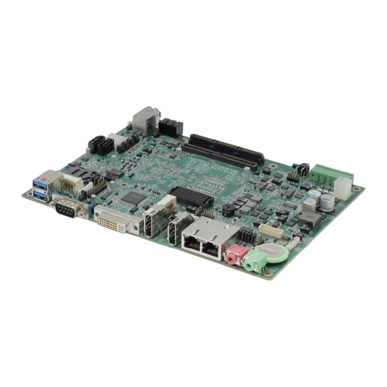
OXY5737A User’s Manual V1.1 1.3 Board Placement www.perfectron.com... -
Page 12: Mechanical Drawings
OXY5737A User’s Manual V1.1 1.4 Mechanical Drawings www.perfectron.com... -
Page 13: Chapter 2: Jumpers And Connectors
OXY5737A User’s Manual V1.1 Chapter 2: Jumpers and Connectors 2.1 Jumpers and connectors list Label Function BAT1 BATTERY connector DIMMA1 DDR3 SO DIMM Socket LVDS1 LVDS CONNECTOR MCARD1 Mini PCIE Card Slot<COLAY M SATA> MINI MPCIE Mini PCIE Card Slot... -
Page 14: Jumper Settings
OXY5737A User’s Manual V1.1 LED1 LAN1 LED STATUS LED2 LAN2 LED STATUS LED3 POWER/HDD LED POWER BUTTON FPR5 RESET POWER BUTTON JBKL1 LVDA POWER BOX HEADER Front Panel LAN LED 2.2 Jumper Settings DIMMA1: DDR3 SO DIMM Socket PIN DEFINITION PIN DEFINITION PIN DEFINITION PIN DEFINITION PIN DEFINITION PIN DEFINITION... -
Page 15: Lvds1: Lvds Connector
OXY5737A User’s Manual V1.1 LVDS1: LVDS CONNECTOR PIN DEFINITION PIN DEFINITION LVDS_BCLK LVDS_BCLK# LVDS_A3 LVDS_A3# LVDS_B3 LVDS_B3# LVDS_ACLK LVDS_B2 LVDS_ ACLK # LVDS_B2# LVDS_B1 LVDS_A2 LVDS_B1# LVDS_A2# LVDS_B0 LVDS_A1 LVDS_B0# LVDS_A1# LVDS_A0 LVDS_DCC_SC LVDS_A0# LVDS_DCC_SD LVDS_VDD LVDS_VDD (define by JV12) (define by JV12) MCARD1: Mini PCIE Card Slot<COLAY M SATA>... -
Page 16: Mcard_Sel1: Msata And Mpcie Selection
OXY5737A User’s Manual V1.1 MCARD_SEL1: mSATA and mPCIE selection Jumper Function description Setting mPCIE mSATA Default setting: 2-3 MINI MPCIE: Mini PCIE Card Slot PIN DEFINITION PIN DEFINITION WAKE# 3.3V Reserved Reserved 1.5V CLKREQ# UIM_PWR UIM_DATA REFCLK- UIM_CLK REFCLK+ UIM_RESET... -
Page 17: Sata-Con Cn3: Serial Ata Connectors
OXY5737A User’s Manual V1.1 SATA-CON CN3: Serial ATA Connectors SATA-CON CN5: Serial ATA Connectors PIN DEFINITION PWR_S4P_H CN4: SATA POWER PWR_S4P_H CN6: SATA POWER PIN DEFINITION LAN1: Intel I218LM LAN2: Intel I210IT LAN1 LAN2 PIN DEFINITION PIN DEFINITION I218_LAN1_MDI0_DP LAN2_MDIP0... -
Page 18: Lan_Sel2: Stackpc/I210 Selection
OXY5737A User’s Manual V1.1 LAN_SEL2: StackPC/I210 selection Jumper Function description Setting STACK PC I210 Default setting: 2-3 F_USB1: USB PIN DEFINITION PIN DEFINITION 1 USBV4 2 USBV5 3 USBD4- 4 USBD5- 5 USBD4+ 6 USBD5+ 7 GND 8 GND 9 NC 10 GND USB3.0 CN18: USB*2... -
Page 19: Mic 1: Audio Jacks Connector
OXY5737A User’s Manual V1.1 MIC 1: Audio Jacks Connector PIN DEFINITION MIC_L MIC1_R LOUT 1: Audio Jacks Connector PIN DEFINITION FRONT_L FRONT_R DIO1: Digital I/O Box Head PIN DEFINITION PIN DEFINITION 1 DIO0 2 DIO1 3 DIO2 4 DIO3 5 DIO4... -
Page 20: Pwrin1: Dc Adapter Power Input
OXY5737A User’s Manual V1.1 ON TIME PIN3 PIN4 12 S 16 S 0= switch to right 1= switch to left OFF TIME PIN5 PIN6 30 S 45 S 60 S 90 S 0= switch to right 1= switch to left... -
Page 21: Dp2: Display Port
OXY5737A User’s Manual V1.1 DP2: DISPLAY PORT PIN DEFINITION PIN DEFINITION 1 DPD_LANEP0 2 GND 3 DPD_LANEN0 4 DPD_LANEP1 5 GND 6 DPD_LANEN1 7 DPD_LANEP2 8 GND 9 DPD_LANEN2 10 DPD_LANEP3 11 GND 12 DPD_LANEN3 13 DDID_DDC_AUX_SEL 14 GND 15 DDID_DDCCLK_AUX_P... -
Page 22: Jv2,3: Com1 Rs232/422/485 Jumper Setting
OXY5737A User’s Manual V1.1 JV2,3: COM1 RS232/422/485 jumper setting Function Description Loopback (Default) 2 RS232 3 RS485 Half-Duplex 4 RS485/422 Full Duplex JV4: COM1 RS485 autoflow setting Jumper Function description Setting Auto flow control disable Auto flow control enable Default setting: 1-2... -
Page 23: Jv2,3,4 And Jp12 Location
OXY5737A User’s Manual V1.1 JV2,3,4 and JP12 location: COM2: RS232/422/485 with 5V/12V selectable DEFINITION COM2P9SEL DTR2#_OPTO CTS2#_OPTO TXD2_OPTO RTS2#_OPTO RXD2_OPTO DSR2#_OPTO DCD2#_OPTO JV6,7: COM2 RS232/422/485 jumper setting No. Function Description 1 Loopback (Default) 2 RS232 3 RS485 Half-Duplex 4 RS485/422 Full-Duplex... -
Page 24: Jv5: Com2 Rs485 Autoflow Setting
OXY5737A User’s Manual V1.1 JV5: COM2 RS485 autoflow setting Jumper Function description Setting Auto flow control disable Auto flow control enable Default setting: 1-2 JP13: COM2 5V/12V selection PIN DEFINITION PIN DEFINITION RI2#_OPTO COM2P9SEL COM2P9SEL COM2P9SEL JV5,6,7 and JP13 location... -
Page 25: Com3: Rs232 With 5V/12V Selectable
OXY5737A User’s Manual V1.1 COM3: RS232 with 5V/12V selectable DEFINITION COM3P9SEL COM3_DTR- COM3_CTS- COM3_TXD COM3_RTS- COM3_RXD COM3_DSR- COM3_DCD- JP7: COM3 +12V/+5V selection Jumper Function description Setting COM3_RI COM4: RS232 with 5V/12V selectable DEFINITION COM4P9SEL COM4_DTR- COM4_CTS- COM4_TXD COM4_RTS- COM4_RXD COM4_DSR- COM4_DCD- www.perfectron.com... -
Page 26: Jp14: Com4 +12V/+5V Selection
OXY5737A User’s Manual V1.1 JP14: COM4 +12V/+5V selection Jumper Function description Setting COM4_RI- COM5: RS232 with 5V/12V selectable DEFINITION COM5P9SEL COM5_DTR- COM5_CTS- COM5_TXD COM5_RTS- COM5_RXD COM5_DSR- COM5_DCD- JP15: COM5 +12V/+5V selection Jumper Function description Setting COM5_RI www.perfectron.com... -
Page 27: Com6: Rs232 With 5V/12V Selectable
OXY5737A User’s Manual V1.1 COM6: RS232 with 5V/12V selectable DEFINITION COM6P9SEL COM6_DTR- COM6_CTS- COM6_TXD COM6_RTS- COM6_RXD COM6_DSR- COM6_DCD- JP16: COM6 +12V/+5V selection Jumper Function description setting COM6_RI- DC Jack PIN DEFINITION PIN DEFINITION 1 GND 2 GND 3 +VIN 4 +VIN... -
Page 28: Con A1: Connector A Top
OXY5737A User’s Manual V1.1 CON A1: CONNECTOR A TOP PIN DEFINITION PIN DEFINITION PIN DEFINITION PIN DEFINITION PIN DEFINITION PIN DEFINITION 1 USB_OC#6 2 BUF_PLT_RST- 53 3V3_DU 54 3V3_DU 105 GND 106 CLK_LPC_UART 3 3.3V 4 3.3V 55 3V3_DU 56 GND... -
Page 29: Jv8,9,10,11: Lvds Panel Selection Jumper Setting
OXY5737A User’s Manual V1.1 JV8,9,10,11: LVDS Panel selection jumper setting Color depth JV10 JV11 (Pixel) (Line) 18-bit 2 1024 768 24-bit 3 1024 768 18-bit 4 1280 800 18-bit 5 1280 1024 24-bit 6 1366 768 24-bit 7 1440 900... -
Page 30: Jv12: Lvds_Vdd Power Select
OXY5737A User’s Manual V1.1 JV12: LVDS_VDD power select Jumper Function description Setting 3.3V 5.0V Default setting: 1-2 JV8,9,10,11,12 location: www.perfectron.com... -
Page 31: Fpe1: Stackpc Fpe Top Connector
OXY5737A User’s Manual V1.1 FPE1: StackPC FPE Top Connector PIN DEFINITION PIN DEFINITION PIN DEFINITION PIN DEFINITION PIN DEFINITION 1 NC 2 NC 3 NC 4 NC 5 NC 11 GND 12 NC 13 GND 14 NC 15 GND 21 NC... -
Page 32: Led1: Lan1 Led Status
OXY5737A User’s Manual V1.1 LED1: LAN1 LED STATUS LED1 Light Dark Flash 1000M 100M GREEN LINK UNLINK ACTIVITY LED2: LAN2 LED STATUS LED2 Light Dark Flash 1000M 100M GREEN Link Un-link Activity LED3: POWER/HDD LED LED2 Light Dark Flash HDD un-access HDD access... -
Page 33: Fp1: Front Panel
OXY5737A User’s Manual V1.1 FP1: Front Panel PIN DEFINITION PIN DEFINITION 1 HDLED+ 2 PLED+ 3 HDLED- 4 GND 5 GND 6 EC_PWR_BTN 7 EXT_RESET# 8 GND 9 NC 10 NC FP3: LAN LED PIN DEFINITION PIN DEFINITION 1 3V3M... -
Page 34: Chapter 3: Getting Started
Chapter 3: Getting Started 3.1 Installing System Memory The OXY5737A supports 1 x DDR3 1333 Swissbit XR-DIMM up to 8GB w/ECC (Top Side) Disconnect all power supplies to the board before installing a memory module to prevent damage to the board and memory module. - Page 35 OXY5737A User’s Manual V1.1 3. Insert the module firmly into the desired slot until the slot lock and secure the memory module. 4. After insert the module to the desire slot, drive screws tighten with memory module’s crew hole and bolt on PCB board.
-
Page 36: Chapter 4: Ami Bios Utility
OXY5737A User’s Manual V1.1 Chapter 4: AMI BIOS UTILITY This chapter provides users with detailed descriptions on how to set up a basic system configuration through the AMI BIOS setup utility. 4.1 Starting To enter the setup screens, perform the following steps: •... -
Page 37: Main Menu
OXY5737A User’s Manual V1.1 4.3 Main Menu The Main menu is the screen that first displays when BIOS Setup is entered, unless an error has occurred. You could setup these items on the Main menu: System Language: Choose the system default language. -
Page 38: Advanced Menu
OXY5737A User’s Manual V1.1 System Time: Set the time. Use Tab to switch between time elements. Access Level Displays the access level of the current user in the BIOS. 4.4 Advanced Menu This section allows you to configure and improve your system and allows you to set up some system features according to your preference. -
Page 39: Pci Subsystem Settings
OXY5737A User’s Manual V1.1 4.4.1 PCI Subsystem Settings PCI, PCI-X and PCI Express settings. PCI Common Settings PCI Latency Timer: Value to be programed into PCI Latency Timer Register. VGA Palette Snoop: Enable or disable VGA Palette Registers Snooping. PERR# Generation: Enables or Disables PCI Device to Generate PERR#. -
Page 40: Pci Express Settings
OXY5737A User’s Manual V1.1 PCI Express Settings Change PCI Express Devices Settings. PCI Express Device Register Settings Relaxed Ordering: Enables or Disables PCI Express Device Relaxed Ordering. Extended Tag: If ENABLED allows Device to use 8-bit Tag field as a requester. -
Page 41: Acpi Settings
OXY5737A User’s Manual V1.1 4.4.2 ACPI Settings System ACPI Parameters. Enable ACPI Auto Configuration Enable/disable BIOS ACPI Auto Configuration. Enable Hibernation Enables or Disables system ability to hibernate (OS/S4 sleep state). This option may be not effective with some OS. -
Page 42: Cpu Configuration
OXY5737A User’s Manual V1.1 4.4.3 CPU configuration CPU Configuration Parameters. www.perfectron.com... - Page 43 OXY5737A User’s Manual V1.1 Hyper-threading Enable for windows XP and Linux(OS optimized for Hyper-Threading Technology) and Disabled for other OS (OS not optimized for Hyper-Threading Technology). When Disabled only one thread per enabled core is enabled. www.perfectron.com...
- Page 44 OXY5737A User’s Manual V1.1 Active Processor Cores Number of cores to enable in each processor package. Overclocking lock FLEX_RATIO(194) MSR. Limit CPUID Maximum Disable for Windows XP. Execute Disable Bit XD can prevent certain classes of malicious buffer overflow attecks when combined with a supporting OS.
- Page 45 OXY5737A User’s Manual V1.1 Energy performance Optimize between performance and power savings. Package power limit lock: When enabled PACKAGE_POWER_LIMIT MSR will be locked and a reset will be required to unlock the register. CPU Power limit1: CPU power limit1 value...
- Page 46 OXY5737A User’s Manual V1.1 auto-demote information. Package C state demotion: enable package C state demotion C1 state auto undemotion: undemotion from demoted C1. C3 state auto undemotion: undemotion from demoted C1. Package C state undemotion: enable package C state undemotion C state Pre-wake: Enable or disable C state Pre-Wake feature.
-
Page 47: Sata Configuration
OXY5737A User’s Manual V1.1 CPU DTS Disabled: ACPI thermal management uses EC reported temperature value. Enabled: ACPI thermal management uses DTS SMM mechanism to obtain CPU temperature values. Out of Spec: ACPI Thermal Management uses EC reported temperature values and DTS SMM is used to handle Out of spec. - Page 48 OXY5737A User’s Manual V1.1 SATA Controller(s) Enable or disable SATA device. SATA Mode Selection Determines how SATA controller(s) operate. The options are: IDE, AHCI, RAID SATA Test Selection Enable or disable Test Mode Aggressive LPM Support Enable PCH to aggressively enter link power state.
-
Page 49: Software Feature Mask Configuration
OXY5737A User’s Manual V1.1 Software Feature Mask Configuration RADI OROM/RST driver will refer to the SWFW configuration to enable or disable the storage features. RAID0: Enable or disable RAID0 feature. RAID1: Enable or disable RAID1 feature. RAID10: Enable or disable RAID10 feature. - Page 50 OXY5737A User’s Manual V1.1 Serial ATA Port 2 Port 2: Enable or disable SATA port Hot Plug: Designates this port as Hot Pluggable. External SATA: External SATA support. SATA device type: Identify the SATA port is connected to Solid State Drive or Hard Disk Drive.
-
Page 51: Intel Rapid Start Technology
OXY5737A User’s Manual V1.1 4.4.5 Intel Rapid Start Technology Enable or disable Intel Rapid Start Technology 4.4.6 PCH-FW Configuration Configure Management Engine Technology Parameters. www.perfectron.com... -
Page 52: Firmware Update Configuration
OXY5737A User’s Manual V1.1 MDES BIOS Status Code Enable/Disable MDES BIOS Status Code. Firmware Update Configuration Configure Management Engine Technology Parameters. Me FW Image Re-Flash: Enable/Disable Me FW Image Re-Flash function. 4.4.7 Intel Anti-Theft Technology Configuration Disabling Intel AT allow user to login to platform. This is strictly for testing only. This does not disable Intel AT services in ME. -
Page 53: Amt Configuration
OXY5737A User’s Manual V1.1 4.4.8 AMT Configuration Configure Active Management Technology Parameters. Intel AMT Enable/Disable Intel Active Management Technology BIOS Extension. Note: iAMT H/W is always enabled. This option just controls the BIOS extension execution. If enabled, this requires additional firmware in the SPI device. - Page 54 OXY5737A User’s Manual V1.1 Un-Configure ME OEMFlag Bit 15: Un-Configure ME without password. Amt Wait Timer Set Timer to wait before sending ASF_GET_BOOT_OPTIONS. Disable ME Set ME to Soft Temporary Disabled. Enable/Disable Alert Specification Format. Activate Remote Assistance Process Trigger CIRA boot.
-
Page 55: Usb Configuration
OXY5737A User’s Manual V1.1 4.4.9 USB Configuration USB Configuration Parameters. Legacy USB Support Enables legacy USB support. AUTO option disables legacy support if no USB devices are connected. DISABLE option will keep USB devices available only for EFI applications. USB3.0 Support Enable/Disable USB3.0 (XHCI) Controller support. -
Page 56: It8786 Super Io Configuration
OXY5737A User’s Manual V1.1 USB hardware delays and time-outs: USB transfer time-out: The time-out value for Control, Bulk, and Interrupt transfers. The options are 1 sec, 5 sec, 10 sec, 20 sec. Device reset time-out: USB mass storage device Start Unit command time-out. The options are 10 sec, 20 sec, 30 sec, 40 sec. -
Page 57: Serial Port 2 Configuration
OXY5737A User’s Manual V1.1 Serial Port 2 Configuration Set Parameters of Serial Port 1 (COMB). Serial Port: Enable or Disable Serial Port (COM). Device Settings: IO=2F8h, IRQ=3 Change Settings: Select an optimal setting for Super IO device. Serial Port 3 Configuration Set Parameters of Serial Port 2 (COMC). -
Page 58: It8786 Hw Monitor
OXY5737A User’s Manual V1.1 4.4.11 IT8786 HW Monitor Monitor hardware status. 4.4.12 Serial Port Console Redirection Console Redirection Console Redirection Enable or Disable. www.perfectron.com... -
Page 59: Console Redirection Setting
OXY5737A User’s Manual V1.1 Console Redirection Setting The Settings specify how the host computer and the remote computer will exchange data. Both computers should have the same or compatible setting. Out-of-Band Mgmt Port: Microsoft Windows Emergency Management Service allows for remote management of a Windows Server OS through a serial port. -
Page 60: Intel I210 Gigabit Network Connection
OXY5737A User’s Manual V1.1 Network Stack Enable/Disable UEFI network stack 4.4.14 Intel I210 Gigabit Network Connection Configure Gigabit Ethernet device parameters. PORT CONFIGURATION MENU NIC Configuration: Configure Boot Protocol, wake on LAN, Link Speed, and VLAN. Blink LEDs: Identify the physical network port by blinking the associated LED. -
Page 61: Chipset
OXY5737A User’s Manual V1.1 4.5 Chipset This section gives you functions to configure the system based on the specific features of the chipset. The chipset manages bus speeds and access to system memory resources. 4.5.1 PCH IO configuration www.perfectron.com... -
Page 62: Pci Express Configuration
OXY5737A User’s Manual V1.1 PCI Express Configuration PCI Express Configuration settings PCIE Root Port Function Swapping: Enable or disable PCI Express PCI Express Root Port Function Swapping. Subtractive Decode: Enable or disable PCI Express Subtractive Decode. PCI Express Root Port1 PCI Express Root Port1 setting. -
Page 63: Pci Express Root Port2
OXY5737A User’s Manual V1.1 PCI Express Root Port2 control the PCI Express Root port, the options are enabled/disabled. ASPM Support: Set the ASPM Level: Force L0s – Force all links to L0s State: AUTO – BIOS auto configure: DISABLE – Disables ASPM. -
Page 64: Pci Express Root Port3
OXY5737A User’s Manual V1.1 PCI Express Root Port3 control the PCI Express Root port, the options are enabled/disabled ASPM Support: Set the ASPM Level: Force L0s – Force all links to L0s State: AUTO – BIOS auto configure: DISABLE – Disables ASPM. -
Page 65: Pci Express Root Port5
OXY5737A User’s Manual V1.1 PCI Express Root Port5: control the PCI Express Root port, the options are enabled/disabled ASPM Support: Set the ASPM Level: Force L0s – Force all links to L0s State: AUTO – BIOS auto configure: DISABLE – Disables ASPM. -
Page 66: Pci Express Root Port6
OXY5737A User’s Manual V1.1 PCI Express Root Port6 control the PCI Express Root port, the options are enabled/disabled ASPM Support: Set the ASPM Level: Force L0s – Force all links to L0s State: AUTO – BIOS auto configure: DISABLE – Disables ASPM. -
Page 67: Pci Express Root Port7
OXY5737A User’s Manual V1.1 PCI Express Root Port7 control the PCI Express Root port, the options are enabled/disabled ASPM Support: Set the ASPM Level: Force L0s – Force all links to L0s State: AUTO – BIOS auto configure: DISABLE – Disables ASPM. -
Page 68: Pci Express Root Port8
OXY5737A User’s Manual V1.1 PCI Express Root Port8 control the PCI Express Root port, the options are enabled/disabled ASPM Support: Set the ASPM Level: Force L0s – Force all links to L0s State: AUTO – BIOS auto configure: DISABLE – Disables ASPM. - Page 69 OXY5737A User’s Manual V1.1 Azalia Docking Support: Enable or disable Azalia Docking Support of Audio Controller. Azalia PME: Enable or disable Power Management capability of Audio Controller. PCH LAN Controller Enable or disable onboard NIC. Wake on LAN: Enable or disable integrated LAN to wake the system. (The Wake On LAN cannot be disabled if ME is on at Sx state.)
-
Page 70: System Agent Sa
OXY5737A User’s Manual V1.1 4.5.2 System AGENT SA VT-d Check to enable VT-d function on MCH. Graphics Configuration Graphics Turbo IMON Current: Graphics turbo IMON current values supported (14-31). Primary Display: select which of AUTO/IGFX/PEG/SG graphics device should be primary display or select SG for switchable GFX Primary PEG: Select Auto/PEG1/PEG2 Graphics device should be Primary PEG. -
Page 71: Lcd Control
OXY5737A User’s Manual V1.1 LCD Control Primary IGFX Boot Display: Select the Video Device which will be activated during POST. This has no effect if external graphics present. Secondary boot display selection will appear based on your selection. VGA modes will be supported only on primary display. -
Page 72: Boot
OXY5737A User’s Manual V1.1 4.6 Boot This section is used to configure the boot features. Setup Prompt Timeout Number of seconds to wait for setup activation key. 65535(0xFFFF) means indefinite waiting. Bootup NumLock State Select the keyboard NumLock state. Quiet Boot Enables or disables Quiet Boot option. -
Page 73: Csm16 Parameters
OXY5737A User’s Manual V1.1 Hard Drive BBS Priorities Set the order of the legacy devices in this group CSM16 Parameters Set the order of the legacy devices in this group GateA20 Active: UPON REQUEST – GA20 can be disabled using BIOS serices.ALWAYS-do not allow disabling GA20;... -
Page 74: Save And Exit
OXY5737A User’s Manual V1.1 4.8 Save and Exit This screen provides functions for handling changes made to the BIOS settings and the exiting of the Setup program. Save Changes and Exit Exit system setup after saving the changes. Discard Changes and Exit Exit system setup without saving any changes. - Page 75 OXY5737A User’s Manual V1.1 Restore Defaults Restore/Load Default values for all the setup options. Save as User Defaults Save the changes done so far as User Defaults. Restore user Defaults Restore the User Defaults to all the setup options. Launch EFI Shell from filesystem device Attempts to launch EFI Shell application (Shellx64.efi) from one of the available filesystem devices.
Need help?
Do you have a question about the OXY5737A and is the answer not in the manual?
Questions and answers