
Related Manuals for PerfecTron OXY5740C


Summary of Contents for PerfecTron OXY5740C
- Page 1 Version 1.0 Quick Installation Guide Revision Date: Nov.13.2019 OXY5740C Intel® QM175 EBX SBC, Kabylake i7-7820EQ (4C x 3.7/3.0 GHz), 8M Cache www.perfectron.com...
-
Page 2: Safety Information
Safety Information 1. Electrical safety • To prevent electrical shock hazard, disconnect the power cable from the electrical outlet before relocating the system. • When adding or removing devices to or from the system, ensure that the power cables for the devices are unplugged before the signal cables are connected. -
Page 3: Revision History
Revision History Revision Date(dd/mm/yyyy) Changes Version 1.0 11/11/2019 Initial release Packing list: □ CD (Driver + user's manual) If any of the above items is damaged or missing, please contact your local distributor. -
Page 4: Table Of Contents
Table of Contents Chapter 1: Product Information Safety Information ..........................1 1. Electrical safety ........................1 2. Operation safety ........................1 Statement ............................1 Revision History ..........................2 Packing list: ............................2 Optional Accessories: ........................2 Table of Contents ........................... 3-4 Chapter 1: Product Information ...................... - Page 5 CN10: LPC (Update BIOS) ....................15 DP1: DISPLAY PORT ......................15 DP2: DISPLAY PORT ......................156 SIM_CARD1: SIM card socket ..................156 DVI: DVI-D ........................16 COM1: RS232/422/485 with 5V/12V selectable ............... 16 JP4: COM1 5V/12V selection ..................16 JP5: COM2 5V/12V selection ..................16 COM2: RS232....
-
Page 6: Chapter 1: Product Information
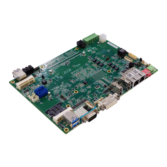
Chapter 1: Product Information 1.1 Block Diagram... -
Page 7: Key Features
1.2 Key Features System CPU Type Intel® Kabylake-H Core™ i7/i5, BGA type Intel® Core™ i7-7820EQ (8M Cache, up to 3.70 GHz) Intel® Core™ i5-7440EQ (6M Cache, up to 3.60 GHz) Chipset Intel® Haswell QM175 PCH Memory Type 1 x DDR4 SO-DIMM up to 16GB SDRAM BIOS AMI®... - Page 8 3 x RS232 (COM2 with 5V/12V selectable) LVDS 2 x 15-pin 2 x 10-pin, 6 in/2 out with isolation SIM card holder Power Requirements Input Voltage 12 VDC (4-pin terminal block for V+, V+, V-, V-) Mechanical and Environment Form Factor Power Type 12V DC-in Dimension...
-
Page 9: Board Placement
1.3 Board Placement... -
Page 10: Chapter 2: Jumpers And Connectors
Chapter 2: Jumpers and Connectors 2.1 Jumpers and connectors list Label Function BAT1 BATTERY connector DIMM0 DDR4 SO DIMM Socket CN19 LVDS CONNECTOR MCARD1 Mini PCIE Card Slot<Full size Co-lay mSATA> JP14 mSATA and mPCIE selection MCARD2 Mini PCIE Card Slot (Half Size) CN1/CN3 Serial ATA Connectors CN2/CN4... -
Page 11: Jumper Settings
2.2 Jumper Settings CN19: LVDS CONNECTOR PIN DEFINITION PIN DEFINITION LVDS_BCLK LVDS_BCLK# LVDS_A3 LVDS_A3# LVDS_B3 LVDS_B3# LVDS_ACLK LVDS_B2 LVDS_ ACLK # LVDS_B2# LVDS_B1 LVDS_A2 LVDS_B1# LVDS_A2# LVDS_B0 LVDS_A1 LVDS_B0# LVDS_A1# LVDS_A0 LVDS_DCC_SC LVDS_A0# LVDS_DCC_SD LVDS_VDD LVDS_VDD (define by JP3) (define by JP3) SW3: LVDS Resolution select DEFINITION on on on on 800*600/18bit (single) -
Page 12: Cn18: Inverter Connector
CN18: Inverter connector PIN DEFINITION BL_EN LVDS0_BKL_CTRL_R 10 GND CPU FAN: CPU FAN Connector PIN DEFINITION CPUFAN_PWN CPUFAN_IO CPUFAN_VCC CN1/CN3: Serial ATA Connectors PIN DEFINITION CN2/CN4: SATA POWER Connector PIN DEFINITION CN17: Digital I/O Box Head PIN DEFINITION PIN DEFINITION 1 VCC 2 GND 3 DI_0... -
Page 13: Jp14: Mcard1 Msata And Mpcie Selection
JP14: MCARD1 mSATA and mPCIE selection Jumper Function description Setting mPCIE mSATA Default setting: 1-2 MCARD1: Mini PCIE Card Slot<COLAY M SATA> PIN DEFINITION PIN DEFINITION WAKE# 3.3VAUX COEX1 COEX2 1.5V CLKREQ# UIM_PWR UIM_DATA REFCLK- UIM_CLK REFCLK+ UIM_RESET UIM_VPP Reserved Reserved W_Disable# PERST#... - Page 14 MCARD2: Mini PCIE Card Slot PIN DEFINITION PIN DEFINITION WAKE# 3.3V Reserved Reserved 1.5V CLKREQ# UIM_PWR UIM_DATA REFCLK- UIM_CLK REFCLK+ UIM_RESET UIM_VPP Reserved Reserved W_Disable# PERST# PERn0 3.3Vaux PERp0 1.5V SMB_CLK PETn0 SMB_DATA PETp0 USB_D- Reserved USB_D+ Reserved Reserved LED_WWAN# Reserved LED_WLAN# Reserved...
-
Page 15: Cn20: Usb 2.0
CN20: USB 2.0 PIN DEFINITION 1 5V 2 USB1- 3 USB1+ 4 GND 5 GND 6 5V 7 USB2- 8 USB2+ 9 GND 10 GND CN21: USB 2.0 PIN DEFINITION 1 5V 2 USB1- 3 USB1+ 4 GND 5 GND 6 5V 7 USB2- 8 USB2+... -
Page 16: Cn6: Audio Jacks Connector (Mic)
CN6: Audio Jacks Connector (MIC) PIN DEFINITION MIC_L MIC1_R CN7: Audio Jacks Connector (Line-Out) PIN DEFINITION FRONT_L FRONT_R CN22: DC Adapter Power Input PIN DEFINITION +VIN +VIN DC_JACK1: DC-IN PIN DEFINITION PIN DEFINITION 1 GND 2 GND 3 +VIN 4 +VIN CN10: LPC (Update BIOS) PIN DEFINITION 1 GND... -
Page 17: Sim_Card1: Sim Card Socket
DP2: DISPLAY PORT PIN DEFINITION PIN DEFINITION 1 DPD_LANEP0 2 GND 3 DPD_LANEN0 4 DPD_LANEP1 5 GND 6 DPD_LANEN1 7 DPD_LANEP2 8 GND 9 DPD_LANEN2 10 DPD_LANEP3 11 GND 12 DPD_LANEN3 13 DDID_DDC_AUX_SEL 14 GND 15 DDID_ AUXP 16 GND 17 DDID_ AUXN 18 DPD_DET 19 GND... -
Page 18: Jp4: Com1 5V/12V Selection
JP4: COM1 5V/12V selection PIN DEFINITION PIN DEFINITION RI1#_OPTO COM1P9SEL COM1P9SEL COM1P9SEL JP5: COM2 5V/12V selection PIN DEFINITION PIN DEFINITION RI1#_OPTO COM1P9SEL COM1P9SEL COM1P9SEL COM2: RS232, with 5V/12V selectable DEFINITION COM2P9SEL DTR- CTS2- TXD2- RTS2- RXD- DSR- DCD- COM3/4: RS232 DEFINITION DTR- CTS-... -
Page 19: Led1: Lan1 Led Status
LED1: LAN1 LED STATUS LED1 Light Dark Flash 1000M 100M GREEN LINK UNLINK ACTIVITY LED2: LAN2 LED STATUS LED2 Light Dark Flash 1000M 100M GREEN Link Un-link Activity LED3: POWER/HDD LED LED2 Light Dark Flash HDD un-access HDD access GREEN Power On Power Off SW1: POWER BUTTON PIN DEFINITION ON NO LIGHT... -
Page 20: Fp2: Lan Led
FP2: LAN LED PIN DEFINITION PIN DEFINITION 1 3V3M 2 3V3M 3 LAN_LED_LNK#_ACT 4 LAN2_ACT# 5 LAN_LED_LNK_1000# 6 LAN2_LED_1000- 7 LAN_LED_LNK_100# 8 LAN2_LED_100- Plug LED cable to FP2 pin header Active LED: plug 1-3 pin Single 1000M LED: plug 1-5 pin Single 100M LED: plug 1-7 pin Dual 1000M LED: plug 5-7 pin... -
Page 21: Chapter 3: Ami Bios Utility
Chapter 3: AMI BIOS UTILITY This chapter provides users with detailed descriptions on how to set up a basic system configuration through the AMI BIOS setup utility. 3.1 Starting To enter the setup screens, perform the following steps: • Turn on the computer and press the <Del> key immediately. •... - Page 22 3.3 Main Menu The Main menu is the screen that first displays when BIOS Setup is entered, unless an error has occurred. System Date Use this function to change the system date. Select System Date using the Up and Down <Arrow> keys. Enter the new values through the keyboard.
-
Page 23: Cpu Configuration
3.4.1 CPU Configuration 3.4.2 Power & Performance... -
Page 24: Pch-Fw Configuration
3.4.3 PCH-FW Configuration 3.4.4 ACPI Setting... -
Page 25: It8786 Super Io Configuration
3.4.5 IT8786 Super IO Configuration User can choose a mode (RS232/RS422/RS485) on each serial port. -
Page 27: Hardware Monitor
3.4.6 Hardware Monitor... -
Page 28: Csm Configuration
3.4.7 CSM Configuration 3.5 Chipset... -
Page 29: Sa Configuration
3.5.1 SA Configuration 3.5.1.1 Graphics Configuration... -
Page 30: Lcd Control
3.5.1.2 LCD Control Primary IGFX Boot Display: Select the Video Device which will be activated during POST. This has no effect if external graphics present. Secondary boot display selection will appear based on your selection. VGA modes will be supported only on primary display. LCD Panel Type: Select LCD panel used by Internal Graphics Device by selecting the appropriate setup item. -
Page 31: Pch-Io Configuration
Backlight control: backlight control setting Panel Color Depth: select the LFP panel color depth. 3.5.2 PCH-IO Configuration 3.6 Security 3.7 Boot... -
Page 32: Save & Exit
Bootup NumLock State: Select the keyboard NumLock state. Quiet Boot: Enables or disables Quiet Boot option. Fast Boot: Enables or disables boot with initialization of a minimal set of devices required to launch active boot option. Has no effect for BBS boot options. Boot option priorities Boot Option #1: Sets the system boot order. - Page 33 This screen provides functions for handling changes made to the BIOS settings and the exiting of the Setup program. Save Changes and Exit Exit system setup after saving the changes. Discard Changes and Exit Exit system setup without saving any changes. Save Changes and Reset Reset the system after saving the changes.
Need help?
Do you have a question about the OXY5740C and is the answer not in the manual?
Questions and answers