
Subscribe to Our Youtube Channel
Related Manuals for PerfecTron OXY5638B


Summary of Contents for PerfecTron OXY5638B
- Page 1 Version 1.2 Revision Date: June. 30. 2017 User's Manual OXY5638B Intel® Broadwell-U EPIC SBC www.perfectron.com...
-
Page 2: Safety Information
• All rights reserved. No part of this publication may be reproduced in any form or by any means, without prior written permission from the publisher. • All trademarks are the properties of the respective owners. • All product specifications are subject to change without prior notice www.perfectron.com... -
Page 3: Revision History
Add connector P/N 2017/6/30 Section 2.2 Onboard and mating connector types Packing list □ OXY5638B EPIC SBC □ CD (Driver + user's manual) Optional Accessories □ Cable Kits If any of the above items is damaged or missing, please contact your local distributor. -
Page 4: Table Of Contents
DCIN: DC-IN +12V ......................... 14 AUDIO1 ..........................14 AUDIO ........................... 14 BAT1 ............................. 15 LPC ............................15 SATA1 ............................ 15 SATA2 ............................ 15 SATA_PWR ..........................16 DIO1 ............................. 16 DIO2 ............................. 16 COM1 : RS232/422/485 Select in BIOS ................17 www.perfectron.com... - Page 5 3.4.5.2 Serial Port 2 Configuration ................32 3.4.5.3 Serial Port 3 Configuration ................33 3.4.5.4 Serial Port 4 Configuration ................33 3.4.6 Hardware Monitor ...................... 34 3.4.7 F81216SEC Super IO Configuration ................34 3.4.8 SATA Configuration ...................... 35 3.4.9 USB Configuration ....................... 35 www.perfectron.com...
- Page 6 3.5.2.2 BIOS Security Configuration ................41 3.5.2.3 Restore AC Power Loss ..................42 3.5.2.4 Wake on LAN (I218) ..................42 3.6 Security Menu ........................43 3.7 Boot Menu ..........................44 3.7.1 Boot Option ......................... 44 3.8 Save & Exit ..........................45 www.perfectron.com...
-
Page 7: Chapter 1: Product Information
IT8786E UART1 COM1 PCIe x4 Super IO RS232/422/485 COM2 UART2 2x5 pin RS232 USB 2.0 2x5 pin COM3 UART3 2x5 pin RS232 USB 2.0 2x5 pin COM4 UART4 2x5 pin RS232 USB 2.0 USB 3.0 Box Header 2x10 pin www.perfectron.com... -
Page 8: Key Features
Form Factor EPIC SBC Power Type 12V DC-in Dimension 180 mm x 115 mm Operating Temp. -40 to 85°C Storage Temp. -40 to 85°C Relative Humidity 10% to 90%, non-condensing *All specifications and photos are subject to change without notice. www.perfectron.com... -
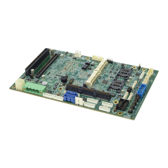
Page 9: Board Placement
OX5638B User's Manual V1.2 1.3 Board Placement www.perfectron.com... -
Page 10: Chapter 2: Jumpers, Connectors And Switch
USB45 2 x USB2.0 USB67 2 x USB2.0 JUSB1 2 x USB3.0 LVDS 24-bit LVDS LVDS_PWR LVDS Power LAN12 2 x GbE LAN LAN_LED LAN LED MINI_PCIE1 Full-size mPCIe slot MINI_PCIE2 Full-size mPCIe/mSATA slot SIM_CARD1 Standard SIM card holder www.perfectron.com... -
Page 11: Onboard And Mating Connector Types
Mating Connectors/Cables Connector Manufacturer Type Number Manufacturer Type Number DCIN PHOENIX 1776715 PHOENIX 1786857 YIMTEX 501MW1*10ST-1R MOLEX 51021-1000 Perfectron Cable SATA_PWR PINREX 743-81-04TW00 0C5020014070300L (200mm) MOLEX 51021-1000 COM1, COM2, YIMTEX 501MW1*10ST-1R Perfectron Cable COM3, COM4 0C5020005101100L (DB9, 150mm) AUDIO1, AUDIO... -
Page 12: Jumper Setting
1440 24-bit Dual Shorted Opened Opened Shorted 1920 1080 24-bit Dual Shorted Opened Opened Opened JP1902: LVDS +5V/+3.3V Voltage Select Jumper Function description Setting 3.3V 5.0V Default setting: 2-3 JP1903: LVDS Backlight Control PIN DEFINITION Backlight UP Backlight Down www.perfectron.com... -
Page 13: Jp2701
JP2702: PIN DEFINITION PIN DEFINITION COM2_RI- COM2P9SEL +5VS COM2P9SEL COM2P9SEL Default setting: 1-2 JP2703: PIN DEFINITION PIN DEFINITION COM3_RI- COM3P9SEL +5VS COM3P9SEL COM3P9SEL Default setting: 1-2 JP2704: PIN DEFINITION PIN DEFINITION COM4_RI- COM4P9SEL +5VS COM4P9SEL COM4P9SEL Default setting: 1-2 www.perfectron.com... -
Page 14: Jp2707: Lvds Backlight +5V/+3.3V Voltage Select
OX5638B User's Manual V1.2 JP2707: LVDS Backlight +5V/+3.3V Voltage Select Jumper Function description Setting 3.3V 5.0V Default setting: 1-2 JCMOS: CMOS Clear Jumper Function description Setting Default Clear CMOS www.perfectron.com... -
Page 15: Connector
8 LINE2_JD 9 LINE2_R 10 LINE2_L AUDIO [YIMTEX 501MW1*10ST-1R] 1 x 10 pin, pitch = 1.25 mm PIN DEFINITION 1 GND 2 MIC1_JD 3 MIC1_R 4 MIC1_L 5 FRONT_JD 6 FRONT_R 7 FRONT_L 8 LINE1_JD 9 LINE1_R 10 LINE1_L www.perfectron.com... -
Page 16: Bat1
1 GND 2 +3v [YIMTEX 501MW1*10ST-1R] 1 x 10 pin, pitch = 1.25 mm DEFINITION 1 GND 2 TPM_IRQ 3 +3.3VSB 4 LPC_AD0 5 LPC_AD1 6 LPC_AD2 7 LPC_AD3 8 LPC_FRAME# 9 PLTRST#_BUF1 10 LPC_CLK_1 SATA1 SATA2 PIN DEFINITION www.perfectron.com... -
Page 17: Sata_Pwr
2 x 5 pin, pitch = 2 mm, 2 mm PIN DEFINITION PIN DEFINITION DIO0 DIO1 DIO2 DIO3 DIO4 DIO5 DIO6 DIO7 DIO2 [PINREX 520-90-10GB00] 2 x 5 pin, pitch = 2 mm, 2 mm PIN DEFINITION PIN DEFINITION DIO8 DIO9 DIO10 DIO11 DIO12 DIO13 DIO14 DIO15 www.perfectron.com... -
Page 18: Com1 : Rs232/422/485 Select In Bios
COM2 : RS232 COM3 : RS232 COM4 : RS232 [YIMTEX 501MW1*10ST-1R] 1 x 10 pin, pitch = 1.25 mm DEFINITION 1 +5V 2 Ground 3 RI(Default)/+5V/+12V 4 DTR- 5 CTS- 6 TXD 7 RTS- 8 RXD 9 DSR- 10 DCD- www.perfectron.com... -
Page 19: Usb45
7 USB5_D- 8 USB5_D+ 9 Ground 10 Ground USB67 [PINREX 712-73-10TWE0] 1 x 10 pin, pitch = 1.25 mm DEFINITION 1 +5V 2 USB6_D- 3 USB6_D+ 4 Ground 5 Ground 6 +5V 7 USB7_D- 8 USB7_D+ 9 Ground 10 Ground www.perfectron.com... -
Page 20: Jusb1
+5V_UBS1 LVDS [ACES 87216-3004] # Mated with [ACES 87219-3004] PIN DEFINITION PIN DEFINITION LVDS_BCLK LVDS_BCLK# LVDS_A3 LVDS_A3# LVDS_B3 LVDS_B3# LVDS_ACLK LVDS_B2 LVDS_ACLK# LVDS_B2# LVDS_B1 LVDS_A2 LVDS_B1# LVDS_A2# LVDS_B0 LVDS_A1 LVDS_B0# LVDS_A1# LVDS_A0 LVDS_DDC_SC 26 LVDS_A0# LVDS_DDC_SD 28 LVDS_VDD LVDS_VDD www.perfectron.com... -
Page 21: Lvds_Pwr
PIN DEFINITION PIN DEFINITION LAN2_MDI0_DP LAN1_MDI0_DP LAN2_MDI0_DN 4 LAN1_MDI0_DN LAN2_MDI1_DP LAN1_MDI1_DP LAN2_MDI1_DN 8 LAN1_MDI1_DN LAN2_MDI2_DP LAN1_MDI2_DP LAN2_MDI2_DN 12 LAN1_MDI2_DN LAN2_MDI3_DP LAN1_MDI3_DP LAN2_MDI3_DN 16 LAN1_MDI3_DN Ground Ground LAN2_1.5V LAN1_1V LAN2_ACT LAN1_ACT +3.3VMLAN +3.3VMLAN LAN2_LED_100 LAN1_LED_100 LAN2_LED_1000 28 LAN1_LED_1000 Ground Ground www.perfectron.com... -
Page 22: Lan_Led
[YIMTEX 501MW1*10ST-1R] 1 x 10 pin, pitch = 1.25 mm DEFINITION 1 GND 2 LAN2_LED_100# 3 LAN2_LED_1000# 4 LAN2_ACT# 5 +3.3VMLAN 6 GND 7 LAN1_LED_100# 8 LAN1_LED_1000# 9 LAN1_ACT# 10 +3.3VMLAN SIM_CARD1 SIM_CARD2 [ASTRON 5190006-007-R] DEFINITION RESET CLOCK DATA www.perfectron.com... -
Page 23: Mini_Pcie1
2 x 5 pin, pitch = 2 mm, 2 mm PIN DEFINITION PIN DEFINITION Plug LED cable to FP1 pin header HDLED+ PLED+ HDD Active LED: plug 1-3 pin HDLED- PLED- Power LED: plug 2-4 pin EC_PWR_BTN Power Button: plug 6-8 pin RSTBTN# www.perfectron.com... -
Page 24: Cpufan
# Mated with [MOLEX 501189-3010] PIN DEFINITION PIN DEFINITION DP1_LANEP0 DP2_LANEP0 DP1_LANEN0 DP2_LANEN0 DP1_LANEP1 DP2_LANEP1 DP1_LANEN1 DP2_LANEN1 DP1_LANEP2 DP2_LANEP2 DP1_LANEN2 DP2_LANEN2 DP1_LANEP3 DP2_LANEP3 DP1_LANEN3 DP2_LANEN3 DP1_AUXP DP2_AUXP DP1_AUXN DP2_AUXN OB_AUX1_EN_N 26 OB_AUX2_EN_N DP1_DET DP2_DET DP1_PWR DP2_PWR CPUFAN [FOXCONN HF2704E-M1] DEFINITION CPUFAN_PWN CPUFAN_IO CPUFAN_VCC www.perfectron.com... -
Page 25: Dimma: 240-Pin Xr-Dimm Slot
197 DQS6# 237 VTT 38 DQ20 78 CB5 118 VDD 158 DQ36 198 VSS 238 VSS 39 VSS 79 CB1 119 VDD 159 VSS 199 DQS6 239 VTT 40 DQ21 80 VSS 120 A3 160 DQ37 200 DQ54 240 VTT www.perfectron.com... -
Page 26: Stackpc: Connector A Top
149 GND 150 GND 47 SMB_DATA_MAIN 48 NC 99 ETH_1_CTREF 100 ETH_0_CTREF 151 LPC_AD2 152 LPC_FRAME 49 SMB_CLK_MAIN 50 NC 101 SPI_MISO_AA 102 SPI_CE0#_F 153 LPC_AD3 154 VRTC 51 SMBALERT# 52 BUS_PS_ON# 103 SPI_SI_F 104 SPI_CE1#_F 155 FUSB_1RTS- 156 FUSB_ORTS www.perfectron.com... -
Page 27: Chapter 3: Ami Bios Utility
The <F4> key saves any changes made and exits the BIOS setup utility. The <Esc> key discards any changes made and exits the BIOS setup utility. Enter The <Enter> key displays a sub-screen or changes a selected or highlighted option in each menu. www.perfectron.com... -
Page 28: Main Menu
OX5638B User's Manual V1.2 3.3 Main Menu The Main menu is the first screen that you will see when you enter the BIOS Setup Utility. www.perfectron.com... -
Page 29: Advanced Menu
The Advanced Menu allows you to configure your system for basic operation. Some entries are defaults required by the system board, while others, if enabled, will improve the performance of your system or let you set some features according to your preference. Setting incorrect field values may cause the system to malfunction. www.perfectron.com... -
Page 30: Cpu Configuration
OX5638B User's Manual V1.2 3.4.1 CPU Configuration This page allows you to configure CPU menu. www.perfectron.com... -
Page 31: Trust Computing
OX5638B User's Manual V1.2 3.4.2 Trust Computing 3.4.3 ACPI Setting www.perfectron.com... -
Page 32: Amt Setting
OX5638B User's Manual V1.2 3.4.4 AMT Setting 3.4.5 IT8786 Super IO Configuration www.perfectron.com... -
Page 33: Serial Port 1 Configuration
OX5638B User's Manual V1.2 3.4.5.1 Serial Port 1 Configuration 3.4.5.2 Serial Port 2 Configuration www.perfectron.com... -
Page 34: Serial Port 3 Configuration
OX5638B User's Manual V1.2 3.4.5.3 Serial Port 3 Configuration 3.4.5.4 Serial Port 4 Configuration www.perfectron.com... -
Page 35: Hardware Monitor
OX5638B User's Manual V1.2 3.4.6 Hardware Monitor 3.4.7 F81216SEC Super IO Configuration * To use this function should stacked with SK303. www.perfectron.com... -
Page 36: Sata Configuration
OX5638B User's Manual V1.2 3.4.8 SATA Configuration 3.4.9 USB Configuration www.perfectron.com... -
Page 37: Intel I218-Lm Ethernet Controller
OX5638B User's Manual V1.2 3.4.10 Intel I218-LM Ethernet Controller 3.4.10.1 NIC Configuration www.perfectron.com... -
Page 38: Intel I210-It Ethernet Controller
OX5638B User's Manual V1.2 3.4.11 Intel I210-IT Ethernet Controller 3.4.11.1 NIC Configuration www.perfectron.com... -
Page 39: Chipset Menu
OX5638B User's Manual V1.2 3.5 Chipset Menu 3.5.1 System Agent (SA) Configuration www.perfectron.com... -
Page 40: Graphics Configuration
OX5638B User's Manual V1.2 3.5.1.1 Graphics Configuration 3.5.1.1.1 LCD Control www.perfectron.com... -
Page 41: Memory Configuration
OX5638B User's Manual V1.2 3.5.1.2 Memory Configuration 3.5.2 PCH-IO Configuration www.perfectron.com... -
Page 42: Pch Azalia Configuration
OX5638B User's Manual V1.2 3.5.2.1 PCH Azalia Configuration 3.5.2.2 BIOS Security Configuration www.perfectron.com... -
Page 43: Restore Ac Power Loss
OX5638B User's Manual V1.2 3.5.2.3 Restore AC Power Loss 3.5.2.4 Wake on LAN (I218) www.perfectron.com... -
Page 44: Security Menu
OX5638B User's Manual V1.2 3.6 Security Menu Use the Security Menu to establish system passwords Administrator Password Set administrator password. User Password Set user Password. www.perfectron.com... -
Page 45: Boot Menu
OX5638B User's Manual V1.2 3.7 Boot Menu This section is used to configure the boot features. 3.7.1 Boot Option www.perfectron.com... -
Page 46: Save & Exit
OX5638B User's Manual V1.2 3.8 Save & Exit www.perfectron.com...
Need help?
Do you have a question about the OXY5638B and is the answer not in the manual?
Questions and answers