
Subscribe to Our Youtube Channel
Related Manuals for PerfecTron INS8145A


Summary of Contents for PerfecTron INS8145A
- Page 1 Version 1.1 Revision Date: October. 02. 2013 User’s Manual INS8145A ATX Industrial Motherboard User’s Manual www.perfectron.com...
-
Page 2: Safety Information
INS8145A ATX MB User’s Manual V1.1 Safety information Electrical safety To prevent electrical shock hazard, disconnect the power cable from the electrical outlet before relocating the system. When adding or removing devices to or from the system, ensure that the power cables for the devices are unplugged before the signal cables are connected. -
Page 3: Revision History
INS8145A ATX MB User’s Manual V1.1 Revision History Revision Date (dd.mm.yyyy) Changes Version 1.0 15.07.2011 Initial release Version 1.1 02.10.2013 Add GPIO feature Packing list □ INS8145A ATX Industrial MB □ I/O shield □ 1 x SATA cable □ 1 x COM ports cable w/o bracket □... -
Page 4: Table Of Contents
INS8145A ATX MB User’s Manual V1.1 Table of Contents SAFETY INFORMATION ............................... 1 ................................1 LECTRICAL SAFETY ................................1 PERATION SAFETY STATEMENT ................................1 REVISION HISTORY..............................2 PACKING LIST ................................2 OPTIONAL ACCESSORIES ............................2 ORDERING INFORMATION ............................2 TABLE OF CONTENTS ..............................3 CHAPTER 1: PRODUCT INFORMATION ........................ - Page 5 INS8145A ATX MB User’s Manual V1.1 KBMS1: PS/2 KB/MS Mini-DIN Connector ....................... 22 CHAPTER 3: GETTING STARTED ..........................23 3.1 I CPU ..............................23 NSTALLING THE 3.2 S ............................... 25 YSTEM EMORY Memory Configurations ............................25 Memory Module Installation ........................... 25 3.3 D...
- Page 6 INS8145A ATX MB User’s Manual V1.1 Integrated Clock Chip Configuration ........................56 Integrated Clock Chip Configuration(ICC Enabled) ....................56 4.6 B ................................57 Gate A20 Active ............................... 57 Option ROM Messages ............................58 Interrupt 19 Capture ..............................58 4.7 S .................................
-
Page 7: Chapter 1: Product Information
INS8145A ATX MB User’s Manual V1.1 Chapter 1: Product Information 1.1 Block Diagram www.perfectron.com... -
Page 8: Key Features
INS8145A ATX MB User’s Manual V1.1 1.2 Key Features Processor & System CPU Type Intel® LGA 1155 socket Core™ i7/i5/i3 processor Core™ i7-2600 3.4 GHz (8M Cache, 95W) Core™ i5-2400 3.1 GHz (6M Cache, 95W) Core™ i3-2120 3.3 GHz (3M Cache, 65W) Pentium®... - Page 9 INS8145A ATX MB User’s Manual V1.1 I /O Inter f ace SATA 2 x SATAIII (6Gb/s, reserve space) 4 x SATAII (3Gb/s, reserve space) *6 x SATA RAID (S/W 0, 1, 5, 10) *2 x SATAIII & 4 x SATAII both support RAID 0,1,5,10 USB Port 10 x USB 1.1/2.0 port...
-
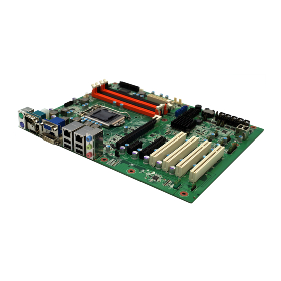
Page 10: Board Placement
INS8145A ATX MB User’s Manual V1.1 1.3 Board Placement www.perfectron.com... -
Page 11: Mechanical Drawing
INS8145A ATX MB User’s Manual V1.1 1.4 Mechanical Drawing www.perfectron.com... -
Page 12: Chapter 2: Jumpers And Connectors
INS8145A ATX MB User’s Manual V1.1 Chapter 2: Jumpers and Connectors 2.1 Onboard Connector List Connector name Function AFP1 HD AUDIO Front Panel ATX12V1 4 pin ATX Power Input Connector AUDIO1 3 Stack-up HD Audio Phone Jack COM1 RS-232 / 422 / 485 COM1... -
Page 13: Jumper Settings
INS8145A ATX MB User’s Manual V1.1 2.2 Jumper Settings JCMOS1: Clear CMOS Jumper Setting Jumper Function description Setting Normal Operation Clear CMOS Default setting is 1-2 JUSB_01: USB1,2,3,4 Power Selection Jumper Function description Setting 5V Standby Default setting is 1-2... -
Page 14: Jcompwr1-6: Com Port Signal / Power Selection
INS8145A ATX MB User’s Manual V1.1 JCOMPWR1-6: COM Port Signal / Power Selection Jumper Function description Setting COM port Pin 9 = RI# 1-2 Enabled COM port Pin 9 = +5V 3-4 Enabled COM port Pin 9 = +12V 5-6 Enabled Default setting is 1-2 2.3 Onboard Connector Pin Assignment... -
Page 15: Com2-6: Rs-232 Box Header
INS8145A ATX MB User’s Manual V1.1 2.7:COM2-6: RS-232 Box Header Pin Signal DCD, Data carrier detect RXD, Receive data TXD, Transmit data DTR, Data terminal ready GND, ground DSR, Data set ready RTS, Request to send CTS, Clear to send... -
Page 16: Fp1: Front Panel 10-Pin Header
INS8145A ATX MB User’s Manual V1.1 FP1: Front Panel 10-Pin Header Pin Signal Pin Signal HDD LED + Power LED + HDD LED - Power LED - Reset Button - Power Button + Reset Button + 8 Power Button -... -
Page 17: Pciex16_1: Standard Pci Express X16 Slot
INS8145A ATX MB User’s Manual V1.1 PCIEX16_1: Standard PCI Express x16 Slot Pin Side B Side A Pin Side B Side A +12V PRSNT#(B) Ground HSIP4 +12V +12V Ground HSIP4 +12V +12V HSOP5 Ground Ground Ground HSON5 Ground SMCLK JTAG2... -
Page 18: Pciex8_1: None Standard Pci Express X8 Slot (X4)
INS8145A ATX MB User’s Manual V1.1 PCIEX8_1: None Standard PCI Express x8 Slot (X4) Pin Side B Side A Pin Side B Side A +12V PRSNT#(B) Reserved Reserved +12V +12V Reserved Reserved +12V +12V Reserved Reserved Ground Ground Reserved Reserved... -
Page 19: Pciex1 Slot
INS8145A ATX MB User’s Manual V1.1 PCIEX1 Slot Pin Side B Side A +12V +3.3V +12V +3.3V +3.3VAUX Ground WAKE# REFCLK+ RST# REFCLK- Ground Ground PETp0 PERp0 PETn0 PERn0 Ground Ground PETp1 PERp1 PETn1 PERn1 SMB_CLK SMB_DAT Ground Ground PETp2... -
Page 20: Usb4.5: Usb2.0 Vertical Connector
INS8145A ATX MB User’s Manual V1.1 USB4.5: USB2.0 Vertical Connector Signal Name Signal Name USB_A- USB_A+ USB_B- USB_B+ USB7-14: USB2.0 Pin Header Signal Name Signal Name USB_A- USB_B- USB_A+ USB_B+ JTAG1: TAG Port Box Header Pin Signal Pin Signal ITP_TCK +3.3V... -
Page 21: Dio1: Digital Input / Output Pin Header
INS8145A ATX MB User’s Manual V1.1 DIO1: Digital Input / Output Pin Header Pin Signal Pin Signal Digital GPIO 0 GP70 2 Digital GPIO 4 GP74 Digital GPIO 1 GP71 4 Digital GPIO 5 GP75 Digital GPIO 2 GP72 6... -
Page 22: Usb 2.0 Connector
INS8145A ATX MB User’s Manual V1.1 RJ-45 + 2 USB 2.0 Connector Signal Signal L12 GLED+ MDI[0]+ L13 OLED- MDI[0]- L14 GLED- MDI[1]+ U1 +5VSV MDI[1]- USB_A- MDI[2]+ U3 USB_A+ MDI[2]- MDI[3]+ U5 +5VSB MDI[3]- USB_B- L10 GND USB_B+ L11 GLED-... -
Page 23: Hdmi Connector
INS8145A ATX MB User’s Manual V1.1 HDMI Connector Pin Signal TMDS Data2+ TMDS Data2 Shield TMDS Data2– TMDS Data1+ TMDS Data1 Shield TMDS Data1– TMDS Data0+ TMDS Data0 Shield TMDS Data0– TMDS Clock+ TMDS Clock Shield TMDS Clock– Reserved Reserved... -
Page 24: Chapter 3: Getting Started
INS8145A ATX MB User’s Manual V1.1 Chapter 3: Getting Started This chapter provides information on how to install components to the INS8145A. Specifically, the installation of CPU, memory modules, and operating system are explained. 3.1 Installing the CPU The INS8145A supports the Intel® 32 nm Sandy Bridge Processor (LGA1155 socket H2) - Page 25 INS8145A ATX MB User’s Manual V1.1 4. Push and remove the protective socket cover (plastic) from the load plate. 5. Unpack the new processor and remove any protective material. 6. Align the processor over the socket and make sure the CPU notch is aligned with the alignment key on the socket.
-
Page 26: System Memory
3.3 Driver Installation The INS8145A drivers for Windows XP 32-bit are located in the following directories on the Driver DVD, or can be downloaded from the Perfectron website (http://www.perfectron.com). Follow the instructions below to install the required INS8145A drivers: 1. - Page 27 INS8145A ATX MB User’s Manual V1.1 3. Install the display driver and utilities by running the program X:\INS8145A Driver\VGA\WIN2KXP_32\setup.exe. Follow the provided instructions and reboot the computer when instructed. 4 Install the LAN driver by running the program X:\INS8145A Driver\LAN\Windows\2000_ XP_2003 Server\PRO2KXP.exe.
-
Page 28: Chapter 4: Ami Bios Utility
INS8145A ATX MB User’s Manual V1.1 Chapter 4: AMI BIOS UTILITY This chapter provides users with detailed descriptions on how to set up a basic system configuration through the AMIBIOS8 BIOS setup utility. 4.1 Starting To enter the setup screens, perform the following steps: Turn on the computer and press the <Del>... -
Page 29: Main Menu
INS8145A ATX MB User’s Manual V1.1 4.3 Main Menu The Main menu is the screen that first displays when BIOS Setup is entered, unless an error has occurred. Note: The default values are displayed in parenthesis, for example: (Enabled). The following information is found on the Main menu: ... -
Page 30: Advanced Menu
INS8145A ATX MB User’s Manual V1.1 4.4 Advanced Menu The Advanced menu, as shown below, The following settings are available: Onboard LAN1 Controller Onboard LAN1 Boot: select this option to enable or disable the LAN1 boot option (Disabled) ... -
Page 31: Onboard Lan1 Controller
INS8145A ATX MB User’s Manual V1.1 Onboard LAN1 Controller Use this setting to enabled or disabled the Onboard LAN1 boot (Enabled). Onboard LAN2 Controller Use this setting to enabled or disabled the onboard LAN2 (Enabled). www.perfectron.com... -
Page 32: Audio Controller
INS8145A ATX MB User’s Manual V1.1 Audio Controller Use this setting to enabled or disabled the onboard audio controller. Power Management Configuration www.perfectron.com... -
Page 33: Acpi Sleep State
INS8145A ATX MB User’s Manual V1.1 ACPI Sleep State The Advanced Configuration and Power Interface (ACPI) specification provides an open standard for device configuration and power management by the operating system. ACPI defines platform-independent interfaces for hardware discovery, configuration, power management and monitoring. -
Page 34: Restore Ac Power Loss
INS8145A ATX MB User’s Manual V1.1 Restore AC Power Loss This menu specifies what state to go to when power is re-applied after a power failure (Power Off). Resume from S3 By PS/2 Keyboard Select this option to enable or disable the PS/2 Keyboard wake up function from S3 mode (Disabled). -
Page 35: Resume From S3 By Ps/2 Mouse
INS8145A ATX MB User’s Manual V1.1 Resume from S3 By PS/2 Mouse Select this option to disable or enable the PS/2 Mouse wake up function from S3 mode (Disabled). Resume By PCI Device Select this option to disable or enable the PCI device wake up function (Disabled). -
Page 36: Resume By Pcie Device
INS8145A ATX MB User’s Manual V1.1 Resume By PCIE Device Select this option to disable or enable the PCIe device wake up function (Disabled). Resume By Ring Device Select this option to disable or enable the Ring device wake up function (Disabled). -
Page 37: Resume By Rtc Alarm
INS8145A ATX MB User’s Manual V1.1 Resume By RTC Alarm Select this option to disable or enable the RTC Alarm device wake up function (Disabled). WatchDog Timer Configuration Select this option to enable or disable the timer countdown for the WatchDog Timer Function (Disabled). -
Page 38: Pci Subsystem Settings
INS8145A ATX MB User’s Manual V1.1 WDT Function Select this option to enable or disable the WDT Function (Disabled). PCI Subsystem Settings Select this option to set the PCI Sybsystem Settings parameters. The device and vendor IDs are displayed. 16-bit vendor IDs is allocated by the PCI-SIG. Features and error reporting are supported by the status register. -
Page 39: Pci Rom Priority
INS8145A ATX MB User’s Manual V1.1 PCI ROM Priority Select this option to set the ROM priority (Legacy or EFI Compatible) PCI Latency Timer Select this option to set the PCI bus clock. Devices that operate in bus-master mode require a timer to limit the use of the PCI bus. -
Page 40: Vga Palette Snoop
INS8145A ATX MB User’s Manual V1.1 VGA Palette Snoop Select this option to enable or disable the VGA palette snoop (Disabled). The VGA Palette Snoop enables PCI cards without a VGA color palette to examine and mimic the video card palette. This feature is required for some MPEG decoder cards, TV cards, and other expansion cards that deal with graphics. -
Page 41: Serr# Generation
INS8145A ATX MB User’s Manual V1.1 SERR# Generation Select this option to enable or disable SERR# function (Default). When enabled the function allows PCI devices to generate SERR numbers. PCIe devices Relaxed Ordering Select this option to enable or disable the Relaxed Ordering function (Default). When enabled the function allow PCI’s delayed transaction protocol to allow transactions to complete out of order. -
Page 42: Pcie Devices Extended Tag
INS8145A ATX MB User’s Manual V1.1 PCIe Devices Extended Tag Select this option to enable or disable the Extended Tag function (Disabled). When enabled the extended tag setting allows existing PCIe device to provide active (D0) device power management sub-state. -
Page 43: Pcie Devices Maximum Payload
INS8145A ATX MB User’s Manual V1.1 PCIe Devices Maximum Payload Select this option to set the Maximum Payload function (Auto).The maximum payload size defined by the PCI Express protocol and connected to send up to 4096 bytes. www.perfectron.com... -
Page 44: Pcie Devices Maximum Request
INS8145A ATX MB User’s Manual V1.1 PCIe Devices Maximum Request Select this option to set the Maximum Read Request function (Auto).This setting determines the largest read request any PCI Express device can generate. Reducing the maximum read request size reduces the hogging effect of any device. -
Page 45: Pci Express Link Setting(Extended Synchronization Patterns)
INS8145A ATX MB User’s Manual V1.1 PCI Express Link Setting(Extended Synchronization patterns) Select this option to enable or disable the Extended Synchronization function (Disabled).If this setting is enabled, the system allows generation of extended synchronization patterns. CPU Configuration Select this option to set CPU configuration settings, such as: CPU ID, CPU Family, and Clock Speed. -
Page 46: Intel Hyper Threading Tech
INS8145A ATX MB User’s Manual V1.1 Intel Hyper Threading Tech Select this option to enable or disable the Intel Hyper Threading technology (Enabled). Hyper-threading technology, (HTT) is Intel's term for its simultaneous multithreading implementation in some of its CPUs. Hyper-threading is an Intel-proprietary technology used to improve performance of multiple tasks running simultaneously. -
Page 47: Sata Configuration
INS8145A ATX MB User’s Manual V1.1 SATA Configuration Select this option set the SATA Configuration settings. SATA Mode on IDE Mode Select this option to set the SATA Mode function. The following options are available: RAID, AHCI and IDE modes. -
Page 48: Serial-Ata Controller 0
INS8145A ATX MB User’s Manual V1.1 Serial-ATA Controller 0 Select this option to set the Serial-ATA Controller 0 function (Disabled). The following settings are available: Disabled, Enhanced, or Compatible. Serial-ATA Controller 1 Select this option to set the Serial-ATA Controller 1 function (Enhanced). The following settings are available: Disabled or Enhanced. -
Page 49: Intel Igd Swsci Opregion
INS8145A ATX MB User’s Manual V1.1 Intel IGD SWSCI OpRegion Select this option to set the Intel integrated graphics device (IGD) SWSCI OpRegion function (Disabled). DVMT Mode Select Select this option to set the DVMT Mode (DVMT Mode). The following settings are available: Fixed Mode, DVMT Mode or Combo Mode. -
Page 50: Usb Configuration
INS8145A ATX MB User’s Manual V1.1 USB Configuration Select this option to set the USB Configuration function. Legacy USB Support Select this option to set the Legacy USB Support function (Enabled). The Legacy USB Support determines if the BIOS should provide support for legacy USB devices. -
Page 51: Super I/O Configuration
INS8145A ATX MB User’s Manual V1.1 Super I/O Configuration Select this option to set the IO Configuration function for onboard serial ports. Select an option to set the Serial Port 1 to 6 and Parallel Port parameters. www.perfectron.com... -
Page 52: H/W Monitor
INS8145A ATX MB User’s Manual V1.1 H/W Monitor Select this option to set the Hardware Monitor settings. The Hardware Monitor reads out all accessible hardware sensors. Depending on the type of available sensors, the following data can be accessed: ... -
Page 53: Pc Health Status
INS8145A ATX MB User’s Manual V1.1 PC Health Status This menu displays the current voltage status of the system. It is for display only. Intel AMT Configuration Select this option to set the AMI Configuration settings. AMT is intended for use with software management applications. It gives a management... -
Page 54: Intel Amt Configuration
INS8145A ATX MB User’s Manual V1.1 Intel AMT Configuration Select this option to set the AMT Configuration settings. 4.5 The Chipset Menu Select this option to configure the North Chipset and other parameters. North Bridge www.perfectron.com... -
Page 55: Low Mmio Align
INS8145A ATX MB User’s Manual V1.1 Low MMIO Align Select an option to configure. The following settings are available: Low MMIO Align (1024MB): select to set this parameter. DMI Gen2 (Enabled): select to enable or disable this parameter. VT-d settings (Disabled): select to enable or disable this parameter. -
Page 56: Me Subsystem
INS8145A ATX MB User’s Manual V1.1 ME Subsystem Select this option to set the ME Subsystem settings. Intel ME Subsystem Configuration Select an option to configure. The following settings are available: ME Subsystem (Enabled): select to enable or disable this parameter. -
Page 57: Integrated Clock Chip Configuration
INS8145A ATX MB User’s Manual V1.1 Integrated Clock Chip Configuration Select this option to set the Integrated Clock Chip Configuration parameters. The Integrated Clock Chip Configuration menu can be accessed to set the overclocking profiles on the BIOS. Performance Tuning can be accessed to adjust the settings in the CPU Configuration and Chipset Configuration submenus. -
Page 58: Boot Menu
INS8145A ATX MB User’s Manual V1.1 4.6 Boot Menu Select this option to set the Boot parameters. The following settings are available: Full Screen LOGO Display (Disabled): select to enable or disable this parameter. Setup Prompt Timeout: select to set this parameter. -
Page 59: Option Rom Messages
INS8145A ATX MB User’s Manual V1.1 Option ROM Messages Select this option to set the Option ROM Messages parameters (Force BIOS). Interrupt 19 Capture Select this option to set the Interrupt 19 Capture parameters (Disabled). www.perfectron.com... -
Page 60: Security Menu
INS8145A ATX MB User’s Manual V1.1 4.7 Security Menu Select this option to set the Security parameters. Select an option to configure. The following settings are available: Administrator Password: Select to set the administrator password. User Password: Select to set the user password. -
Page 61: User Password
INS8145A ATX MB User’s Manual V1.1 User Password Select this option to set the User Password. www.perfectron.com... -
Page 62: Save & Exit Menu
INS8145A ATX MB User’s Manual V1.1 4.7 Save & Exit Menu Select this option to set the Save & Exit parameters. The following settings are available: Save Changes and Reset: Select to set this parameter. Discard Changes and Reset: Select to set this parameter. -
Page 63: Save Change And Reset
INS8145A ATX MB User’s Manual V1.1 Save Change and Reset Select this option to save any changes applied and reset the system. www.perfectron.com... -
Page 64: Discard Changes And Reset
INS8145A ATX MB User’s Manual V1.1 Discard Changes and Reset Select this option to discard any changes applied and reset the system. www.perfectron.com... -
Page 65: Save Changes And Exit
INS8145A ATX MB User’s Manual V1.1 Save Changes and Exit Select this option to save any changes applied and exit the system. www.perfectron.com... -
Page 66: Discard Changes And Exit
INS8145A ATX MB User’s Manual V1.1 Discard Changes and Exit Select this option to discard any changes applied and exit the system. www.perfectron.com... -
Page 67: Save Changes
INS8145A ATX MB User’s Manual V1.1 Save Changes Select this option to save any changes applied. www.perfectron.com... -
Page 68: Discard Changes
INS8145A ATX MB User’s Manual V1.1 Discard Changes Select this option to discard any changes applied. www.perfectron.com... -
Page 69: Restore Defaults
INS8145A ATX MB User’s Manual V1.1 Restore Defaults Select this option to restore the factory default system settings. www.perfectron.com... -
Page 70: Save As User Defaults
INS8145A ATX MB User’s Manual V1.1 Save as User Defaults Select this option to save any changes applied as user defaults. www.perfectron.com... -
Page 71: Restore User Defaults
INS8145A ATX MB User’s Manual V1.1 Restore User Defaults Select this option to restore the user default system settings. www.perfectron.com... -
Page 72: Appendix A Watchdog Timer Setting
INS8145A ATX MB User’s Manual V1.1 APPENDIX A Watchdog Timer Setting After the system stops working for a while, it can be auto-reset by the Watchdog Timer. The integrated Watchdog Timer can be set up in the system reset mode by program. - Page 73 INS8145A ATX MB User’s Manual V1.1 re-set timer :O 2E F6 O 2F M ; M=00,01,02,…FF(See the following table) ↓ IF No re-set timer :WDT time-out, generate RESET IF to disable WDT :O 2E 30 O 2F 00 ; Can be disable at any time...
-
Page 74: Appendix B Digital I/O
INS8145A ATX MB User’s Manual V1.1 APPENDIX B DIGITAL I/O Digital I/O Software Programming Program Example: 4IN/4OUT (W83627DHG) O 2E 87 O 2E 87 O 2E 87 O 2E 87 O 2E 07 O 2E 07 O 2F 09 O 2F 09...
Need help?
Do you have a question about the INS8145A and is the answer not in the manual?
Questions and answers