Table of Contents
Advertisement
Quick Links
Table of Contents
1.1 A Thank-you Note Before You Get Started...........................4
1.2 The Features Of This Manual.................................................................5
1.3 Preliminary Tools................................................................................6
1.4 What's In The Box?.....................................................................7
1.5 Accessory...............................................................................8
2.1 Features of XC Cube........................................................10
2.2 Starting Installing...................................................................11
2.3 Install Hard disk.........................................................................13
2.4 Install Serial ATA hard disk................................................................15
2.5 Install 3.5" Floppy disk or Card reader.............................................16
2.6 Install Optical drive..................................................................17
2.7 Install other device......................................................................19
2.8.1 Install CPU on Socket 478................................................................20
2.8.2 Install CPU on Socket T..............................................................21
2.8.3 Install CPU on Socket 479...........................................................22
2.8.4 Install CPU on Socket A............................................................23
2.8.5 Install CPU on Socket 754.........................................................24
2.8.6 Install CPU on Socket 939............................................................25
2.9 Install CPU Cooler and CPU Fan Connector............................26
2.10 Connecting DRAM to DIMM Sockets.........................................26
2.11 Insert AGP card or PCI card to motherboard........................27
2.12 Connect Keyboard and Mouse.................................................28
2.13 Connect Monitor and tighten screws.........................................28
2.15 Set proper voltage and connect power supply cable..........................29
1
TZ65II_915-OL-E0501A[49.BZ101.0A1].indd
1
2005/2/17, 下午 10:32
Advertisement
Table of Contents

Subscribe to Our Youtube Channel
Related Manuals for AOpen XC Cube TZ915


Summary of Contents for AOpen XC Cube TZ915
-
Page 1: Table Of Contents
Table of Contents I. Getting Start 1.1 A Thank-you Note Before You Get Started......4 1.2 The Features Of This Manual..............5 1.3 Preliminary Tools................6 1.4 What’s In The Box?..............7 1.5 Accessory................8 II. Start To Assemble 2.1 Features of XC Cube............10 2.2 Starting Installing..............11 2.3 Install Hard disk.................13 2.4 Install Serial ATA hard disk..............15 2.5 Install 3.5"... - Page 2 We regret not informing about any changes in usage standards and other related information. AOpen Company reserves the right of altering or modifying the content of this manual. In case of any mistakes or incorrect descriptions, which include those on the products, AOpen makes no guarantee or commitments.
-
Page 3: Getting Start
I. Getting Start TZ65II_915-OL-E0501A[49.BZ101.0A1].indd 2005/2/17, 下午 10:32... -
Page 4: A Thank-You Note Before You Get Started
1.1 A Thank-you Note Before You Get Started First of all, we would like to express our gratitude for purchasing our AOpen specially-designed XC Cube. Once again, this bare-system is designed uniquely to meet all your personal needs with our great industry-designing ability and our everlasting perseverance to the quality of all our products. -
Page 5: The Features Of This Manual
1.2 The Features Of This Manual In this manual, you'll be able to learn how to: ► Set up a personal computer on your own. ► Correctly and safely put everything together and learn something about hardware. ► Learn some practical techniques that make doing the job easier. In addition, this manual DOES NOT offer you: ►... -
Page 6: Preliminary Tools
1.3 Preliminary Tools "A workman must first sharpen his tools if he is to do his work well". Right before you start the assembly, there are some tools that can't be spared. Firstly, the most frequently-used tool is cross screwdriver by which most interior components are fixed. -
Page 7: What's In The Box
1.4 What’s In The Box? Open the XC Cube box, you will find components as follow: ► XC Cube chassis / Drives Cage ► Motherboard (Pre-installed on XC Cube chassis.) ► Power Supply (Pre-installed on XC Cube chassis.) ► CPU cooler ►... -
Page 8: Accessory
1.5 Accessory Beside main components, you are supposed to see the following accessories: ► Fixed screws: After opening the accessory parcel, you'll see the following four different type of screws: As shown in the A s s h o w n i n picture, threads on the picture, the NO.2... -
Page 9: Start To Assemble
II. Start To Assemble TZ65II_915-OL-E0501A[49.BZ101.0A1].indd 2005/2/17, 下午 10:32... -
Page 10: Features Of Xc Cube
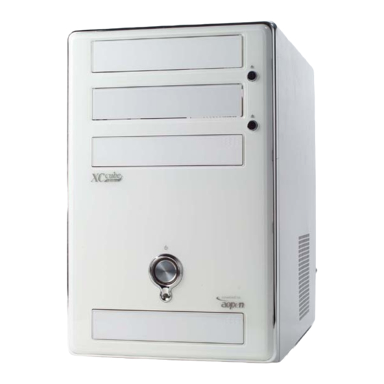
2.1 Features of XC Cube AOpen XC Cube, designed as a Mini-PC, provides you as many advantages as it can. You may find that it is elegant among other traditional PC design that obviously highlighted your individual style and taste with different color panel provided. In addition to it’s unique appearance, AOpen XC Cube is easy to move around in your house, suitable for decoration even in your living room. -
Page 11: Starting Installing
2.2 Starting Installing Unscrew all screws on the chassis. Use your thumb to push the chassis backward to you. Lift the chassis up. Here you may see the internal of the chassis. TZ65II_915-OL-E0501A[49.BZ101.0A1].indd 2005/2/17, 下午 10:32... - Page 12 When you start to take the Front Panel apart, please pay attention to the rib that is located at top of the both side panel. As the left picture shown, the first you can pull it apart toward the both side, then softly pull it away.
-
Page 13: Install Hard Disk
2.3 Install Hard disk Before taking the Hard disk bay out from the left side of the motherboard, please take the screws off that is below the Drives Cage. It takes the Hard disk bay out along the curve slideway. Put the Hard disk into the Hard disk bay, please pay attention to the yellow arrowhead as shown, and take the... - Page 14 There is a transparent plastic cover on the other side of the Hard disk bay. When you install the Hard disk and match the cover, that’s mean the Hard disk is on the suitable position. Please use the screw no.2 to screw it! Don’t remove the cover, because it will help you to install correct next time.
-
Page 15: Install Serial Ata Hard Disk
You can connect the other side of the Hard disk 40pin cable and IDE hander of the Motherboard. Please pay attention to the red cable should aline with the Hard disk and pin 1 of the Motherboard. Yo u c a n r e f e r t o y o u r “ E a s y Installation Guide”... -
Page 16: Install 3.5" Floppy Disk Or Card Reader
2.5 Install 3.5" Floppy disk or Card reader Install 3.5” Floppy disk or Card reader to the first Drive bay of the Drives Cage. The screw aperture of the 3.5” Floppy disk or Card reader aim at the no.1 aperture of the “FDD”... -
Page 17: Install Optical Drive
You can connect the other side of the Floppy disk 34pin cable and Floppy hander of the Motherboard. Please pay attention to the red cable should aline with the Floppy disk and pin 1 of the Motherboard. If you install the Card reader, you can connect the cable to the USB hander of the Motherboard. - Page 18 To stand on your deject button position of the Optical drive, you can adjust the deject lever position of the XC Cube Front Panel. It makes you to press the deject button of the Optical drive accurate. When you install the cable and power cord of the Optical drive 40pin, please pay attention to the red cable should aline with...
-
Page 19: Install Other Device
2.7 Install other device XC Cube TZ Series set up two 5.25” Drive bay and four 3.5” Drive bay to provide you the more devices. When you install the devices, we suggest you the follow order. It will make the XC Cube TZ Series have more thermo performance and expandability. 5.25”... -
Page 20: Install Cpu
2.8 Install CPU 2.8.1 Install CPU on Socket 478 Erect sensor up a bit (it might have been folded while shipped in with Cooler on top of it). After that, erect CPU socket lever up. Then, install CPU onto CPU socket. Press the lever back to CPU socket. -
Page 21: Install Cpu On Socket T
2.8.2 Install CPU on Socket T Remove plastic cap and erect CPU socket lever up. Pull CPU socket plate up and install CPU onto CPU socket. Then press plate back to CPU socket. Press down CPU socket lever to finish CPU installation TZ65II_915-OL-E0501A[49.BZ101.0A1].indd 2005/2/17, 下午... -
Page 22: Install Cpu On Socket 479
2.8.3 Install CPU on Socket 479 Remove plastic membrane from CPU socket and make sure the drop-shaped indicator on socket screw aims at open direction (the default is open). Plastic membrane Drop-shaped indicator Socket screw Match socket Pin 1 and golden arrow, and gently put CPU onto CPU socket. Then lock socket screw clockwise to finish CPU installation. -
Page 23: Install Cpu On Socket A
2.8.4 Install CPU on Socket A Erect CPU socket lever up and gently put CPU onto Socket Press lever back to CPU socket, and then it’s done. TZ65II_915-OL-E0501A[49.BZ101.0A1].indd 2005/2/17, 下午 10:34... -
Page 24: Install Cpu On Socket 754
2.8.5 Install CPU on Socket 754 Erect CPU socket lever up and gently put CPU onto Socket Press lever back to CPU socket, and then it’s done. TZ65II_915-OL-E0501A[49.BZ101.0A1].indd 2005/2/17, 下午 10:35... -
Page 25: Install Cpu On Socket 939
2.8.6 Install CPU on Socket 939 Erect CPU socket lever up and gently put CPU onto Socket Press lever back to CPU socket, and then it’s done. TZ65II_915-OL-E0501A[49.BZ101.0A1].indd 2005/2/17, 下午 10:35... -
Page 26: Install Cpu Cooler And Cpu Fan Connector
2.9 Install CPU Cooler and CPU Fan Connector There is a certain direction for the installation of cooler for optimized air-flow performance within chassis. For details, please refer to "Easy Installation Guide". 2.10 Connecting DRAM to DIMM Sockets DIMM socket is designed in Sky Blue color, which is very easy to recognize. Install memory module evenly into DIMM. -
Page 27: Insert Agp Card Or Pci Card To Motherboard
2.11 Insert AGP card or PCI card to motherboard If you happen to have AGP / PCI Express x16 or PCI card, you may insert them onto the slot as shown. Screw the iron plate off the back panel, and use the screwdriver to pry it out. -
Page 28: Connect Keyboard And Mouse
2.12 Connect Keyboard and Mouse 2.13 Connect Monitor and tighten screws 2.14 Connect Microphone (Speaker or Earphone) and Network cable TZ65II_915-OL-E0501A[49.BZ101.0A1].indd 2005/2/17, 下午 10:35... -
Page 29: Set Proper Voltage And Connect Power Supply Cable
2.15 Set proper voltage and connect power supply cable The voltage supplied by power outlet differs from countries or areas you dwell in. If the outlet is supplied by 110V, please set the switch to 115V. If the outlet is supplied by 220V, please set the switch to 230V. - Page 30 Note TZ65II_915-OL-E0501A[49.BZ101.0A1].indd 2005/2/17, 下午 10:35...
- Page 31 III. Turn On The Power TZ65II_915-OL-E0501A[49.BZ101.0A1].indd 2005/2/17, 下午 10:35...
-
Page 32: Turn On The Power
3.1 Turn on the power Ok, all cables have been properly connected. Are you getting confident of assembling a computer by yourself? The final stage is to turn on the power to check what you have done so far. Now take a short break and have a drink. Then turn on the computer to see how things are going 3.2 Set BIOS (Basic Input / Output System) Not long after activating the power, you’ll see the following screen. - Page 33 After pressing <Delete>, you'll see the following BIOS setup. Now, you can move the cursor by using direction keys on the keyboard. Move the cursor to the option item "Load Setup defaults" and press <Enter> TZ65II_915-OL-E0501A[49.BZ101.0A1].indd 2005/2/17, 下午 10:35...
- Page 34 Then, the following dialogue screen will pop up to confirm the default BIOS values. Please press <Y> to confirm and then press <Enter> Finally, move the cursor to “Save & Exit Setup” and press <Enter> to save the parameters and exit BIOS setup. TZ65II_915-OL-E0501A[49.BZ101.0A1].indd 2005/2/17, 下午...
- Page 35 At the same time, type <Y> in the dialogue box and press <Enter> to exit. Now everything is perfectly finished!! TZ65II_915-OL-E0501A[49.BZ101.0A1].indd 2005/2/17, 下午 10:35...
-
Page 36: Postscripts
We sincerely hope every customer who wants to assemble a computer on his or her own has a wonderful beginning! To learn more about AOpen XC Cube, visit us at http://xc.aopen.com.tw TZ65II_915-OL-E0501A[49.BZ101.0A1].indd... -
Page 37: Appendix
Appendix Install OS into Serial ATA Hard Disk for UX661 Series UX661 is equipped with powerful SiS 964 chip with Serial ATA function. Please notice that when installing OS into Serial ATA hard disk, there will be some limitations due to the limitation of SiS 964 chip. -
Page 38: Raid Driver Installation Guide For Ux661 Series
RAID Driver Installation Guide for UX661 Series By the strength of SiS 964 chip, UX661 provides RAID 0 and 1 functions. User could build RAID in Windows 2000 or Windows XP. For enabling RAID function, it’s needed to install driver from Floppy drive. Please connect Floppy drive to motherboard before starting to install OS. - Page 39 Select the driver for your OS (Windows 2000 or Windows XP) and press <Enter> to install the driver. For more information of RAID installation, please refer to the file "964_180umh030.pdf" in the Utility CD. TZ65II_915-OL-E0501A[49.BZ101.0A1].indd 2005/2/17, 下午 10:36...
-
Page 40: Introduction To Jumper Settings And Other Connectors
Introduction to Jumper Settings and Other Connectors JP14 Clear CMOS You can clear CMOS to restore system default setting. To clear the CMOS, follow the procedure below. 1. Turn off the system and unplug the AC power. 2. Remove ATX power cable from connector PWR2. 3.
Need help?
Do you have a question about the XC Cube TZ915 and is the answer not in the manual?
Questions and answers