Advertisement
Advertisement

Related Manuals for AOpen Digital Engine DE45


Summary of Contents for AOpen Digital Engine DE45
- Page 1 User Guide for DE45 V2.0 2009/04/08...
- Page 2 De genbruge produktet. For yderligere information vedrørende indsamling og genbrug af elektronik-affald (Waste Electrical and Electronic Equipment (WEEE)) er De velkommen til at besøge vores website www.aopen.com og læse nærmere under "Green Products".
- Page 3 Verwijder dit product dan ook alstublieft niet samen met ander huishoudelijk afval. Voor meer informatie over de verzameling en recycling van elektrisch afval en elektronische apparatuur (WEEE), nodigen we u uit om onze homepage te bezoeken www.aopen.com onder "Green Products".
- Page 4 Per ridurre al minimo l'inquinamento ed assicurare la massima protezione dell'ambiente, si prega di riciclare il prodotto. Per maggiori informazioni riguardanti la raccolta ed il riciclaggio delle apparecchiature elettriche ed elettroniche residue (WEEE), siete invitati a visitare la nostra homepage www.aopen.com alla voce "Green Products". Instruksjoner for Resirkulering og Oppsamling (Norweigian) For ĺ...
- Page 5 återvinnas. För vidare information om insamling och återvinning av uttjänta elektriska och elektroniska produkter (Waste Electrical and Electronic Equipment, WEEE), besök avsnittet "Green Products" på vår hemsida, www.aopen.com.
- Page 6 Copyright Copyright of this publication belongs to AOpen Inc. AOpen reserves the right to change the content of this publication without obligation to notify any party of such changes or revisions. No part of this publication may be reproduced, transcribed, transmitted, translated into any language, stored in a retrieval system in any form or by any means electronically, mechanically, optically without the prior written permission of this company.
- Page 7 Safety Instructions 1. Please read these safety instructions carefully. 2. Please keep this User’s Manual for later reference. 3. Please disconnect this equipment from connecter before cleaning. Don’t use liquid or prayed detergent for cleaning. Use moisture sheet or cloth for cleaning. 4.
- Page 8 FCC notice This device has been tested and found to comply with the limits for a Class B digital device pursuant to Part 15 of the FCC Rules. These limits are designed to provide reasonable protection against harmful interference in a residential installation. This device generates, uses, and can radiate radio frequency energy and, if not installed and used in accordance with the instructions, may cause harmful interference to radio communications.
- Page 9 Notice: Peripheral devices Only peripherals (input/output devices, terminals, printers, etc.) certified to comply with Class B limits may be attached to this equipment. Operation with non-certified peripherals is likely to result in interference to radio and TV reception. Caution Changes or modifications not expressly approved by the manufacturer could void the user’s authority, which is granted by the Federal Communications Commission, to operate this computer.
-
Page 11: Table Of Contents
Index 1. Outlook …………..……………………………………………2 2. Product Specification….…………………………...………...4 3. Internal Connectors ………..…………………………………5 4. Packing List……………………………………………………6 5. Chassis and Holder Dimension ……………………………..7 6. Appendix 1 Assembly Guide…..………..………….……….15 7. Appendix 2 Table of Screw and Torque………….………...36... -
Page 12: Outlook
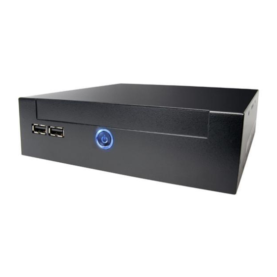
1. Outlook Front IO Front USB Front USB Power Button Power Button... - Page 13 Rear IO Kensington Antenna VGA2 COM port lock hole hole USB 2.0 Line out DC20V/12V HDMI VGA1 Mic in...
-
Page 14: Product Specification
2. Product Specification Socket P Support Intel Core 2 Duo and Celeron CPU, FSB 667/800/1066 MHz Intel GM45 + ICH9M Chipset Chipset Memory Dual Channel Mode, SO-DIMM DDRII x 2, DDRII 667/800 Max memory size : 4GB Integrated VGA Engine in GM45 chipset (Intel GMA X4500MHD) Graphics Expansion mini Card Slot x 1... -
Page 15: Internal Connectors
3. Internal Connectors VGA2 connector Riser Card connector CPU Socket COM port connector SO-DIMM Socket North Bridge GM45 Mini Card slot 1 port USB x 2 PWR SW, LED HDD LED connector Fan PWR connector Front USB x 1... -
Page 16: Packing List
4. Packing List 1 x DE45-HG/PRO system 1 x DE-SATA card 1 x Easy Assembly Guide 1 x Driver CD 1 x 90W Adapter and Power Cord 1 x Card Holder 1 x L type Holder with 8 pcs of M3 screw 4 x M3 - L5 screws 7 x M2 - L3 screws □... -
Page 17: Chassis And Holder Dimension
5. Chassis and Holder Dimension A. Dimension of DE45-HG (unit: mm[inch]) - Page 18 B. LH01 L type Holder(Include 2 piece holder and 8 FPH M3 screws) L type Holder is a versatile holder, you can You can put on the L type Holder on 2 sides, screw it on any place you want. and screw it tightly.
- Page 19 B-3 Dimension of L type Holder. (unit: mm)
- Page 20 C.VM02 Monitor Holder (Include 2 piece holder and 4 FPH M3 and 4 FPH M4 screws) Monitor Holder is base on VESA standard (10cm/7.5cm interval) for you to screw the Digital Engine behind the monitor. You can put on the Holder on monitor VESA mounting hole first, and screw it tightly, then put Digital Engine on VM02 holder and use 4 M3 screws to fix it.
- Page 21 C-2 Dimension of VM02 Monitor Holder (unit: mm)
- Page 22 D. ST01 Vertical Holder (Include 2 piece holder and 8 FPH M3 screws) You can put the Digital Engine Vertical with the You can put the stand(s) on right side, and holder screw it tightly.
- Page 23 D-3 Dimension of ST01 Vertical Holder. (Single Stand) (unit: mm)
- Page 24 D-4 Dimension of ST01 Vertical Holder.(Double Stand) (unit: mm)
-
Page 25: Appendix 1 Assembly Guide
6. Appendix 1 Assembly Guide 1. Open Housing 1-1. 1-2. Detach 2 pcs of the rear side screw ( FPH M3 Push the Upper case to remove it . screw ) by the electric screw driver . Front Side (Screwdriver torque : 5.0±0.2 kgf. cm ) Unscrew Rear Side... - Page 26 1-3. Detach 4 pcs of the supporter screw ( FPH 1-4.Remove Supporter M3 screw )by the electric screw driver (Screwdriver torque : 5.0 ±0.2 kgf. cm )
- Page 27 1-5.You will see the kernel of Digital Engine...
-
Page 28: Install Key Components
2. Install Key components 2-1 Install Memory 2-1-1. Insert the memory on the socket as this angle. Insert DIMM as this angle 30°... - Page 29 2-1-2. Then press the DIMM as flat on the Motherboard, and you will hear the click voice. Make sure it clicks...
- Page 30 2-1-3.Unscrew the CPU cooler 2-1-5. Unscrew CPU socket Counterclockwise direction Unscrew 2-1-4. Remove the cooler...
- Page 31 2-1-6 Put the CPU into the socket, and check 2-1-8. Put on the cooler and screw it tightly the direction. . clockwise direction 2-1-7. Screw the CPU socket. 2-1-9 connect the wire for cooler...
- Page 32 2-2 Install HDD on Supporter without ODD 2-2-1 Install Card Holder and screw it with 1pcs of M2 screw. (Screwdriver torque : 0.7±0.1kgf.cm) Put the Card Holder on the supporter, 2-2-2.Insert the MPI-SATA card into HDD Screw internal card to Card holder with 2pcs of M2 screws.(Screwdriver torque:0.7±0.1kgf.cm)
- Page 33 2-2-3. Put the HDD on support 2-2-4. and screw HDD with 4pcs of FPH M3 Please pay attention to the direction of SATA screw (on both flanks) (Screwdriver torque : 2.5 ±0.1 kgf. cm )
- Page 34 2-3 Install HDD on Supporter with slim ODD 2-3-1 Put slim ODD on the top side of supporter, screw the position 1 and 2 with M2 screw first, then screw position 3 and with M2 screw to fix the slim ODD. (Screwdriver torque : 0.7±0.1kgf.cm)
- Page 35 2-3-2.Insert the MPI-SATA card into HDD 2-3-3 Screw MPI-SATA card to ODD with 2 pcs of M2 screws. (Screwdriver torque : 0.7±0.1kgf.cm) and screw HDD with 4pcs of FPH M3 screw 2-3-4. Put the HDD on support Please pay attention to the direction of SATA (on both flanks) (Screwdriver torque : 2.5 ±0.1 kgf.
- Page 36 2-3-5 FPH M3xL5 Screw FPH M2xL3 Screw...
- Page 37 3. Assemble the Supporter & Upper Case 3-1.Make sure Front USB wire connect to MB...
- Page 38 3-2. Install the supporter (Only HDD is on the supporter now) 3-2-1. Make sure the MPI-SATA card is correctly insert into the socket 3-2-2.Screw 4pcs of M3 screw at the supporter. (Screwdriver torque : 5.0 ± 0.2 kgf.cm)
- Page 39 3-3. Install the supporter (HDD and ODD are on the supporter now) 3-3-1. Make sure the MPI-SATA card is correctly insert into the socket 3-3-2.Screw 4pcs of M3 screw at the supporter. (Screwdriver torque : 5.0 ± 0.2 kgf.cm)
- Page 40 3-4. Assemble the upper case (without ODD) 3-4-1. Connect the power switch wire. 3-4-2. Connect the Front-USB wire to upper-case. 3-4-3. Adjust the USB cable to arrange the cable under the supporter . Accord the photo.
- Page 41 3-5 Assemble the upper case (with ODD) 3-5-1. Remove ODD door on upper case 3-5-2. Connect the power switch wire. 3-5-3.. Accord the photo Connect the 3-5-4. Adjust the USB cable to arrange the Front-USB wire to upper-case cable under the supporter.
- Page 42 3-6.Screw the upper case 3. Screw 2pcs of M3 screw at rear side (Screwdriver torque : 5.0 ±0.2 kgf. cm )
- Page 43 Without slim ODD With slim ODD...
- Page 44 3-7 Assemble Module of Wireless LAN Mini Card or TV Tuner Mini Card 3-7-1. cable and nut 3-7-2. Note the hole shape to adjust the A,B inside housing; C,D outside housing antenna SMA connector to insert into the hole. 3-7-3. Insert a washer to one end of the 3-7-4.
- Page 45 3-7-5. Detach screw and align the notch to 3-7-6. Install the antenna wire with the button Insert mini card into the slot and fix with screw. of the wireless LAN or TV-tuner Mini card . 3-7-7. Arrange the wire to avoid damaging the 3-7-8.
-
Page 46: Appendix 2 Table Of Screw And Torque
7. Appendix 2 Table of Screw and Torque Screw Photo Position Q’ty Screw spec. Torque Screw driver spec. ♁ Rear side FPH M3- L5 5±0. 2 Phillips #2 kgf-cm ♁ FPH M3- L5 2.5±0. 2 Phillips #2 Length ≧ 8cm kgf-cm ♁... - Page 48 P/N:49.ADE01.0630 S/N:099-044-110...
Need help?
Do you have a question about the Digital Engine DE45 and is the answer not in the manual?
Questions and answers